
Specifications
Page 2
Amber light - Battery charge is being charged. White light - Power adapter is connected and the battery is low or critical. 2 Hard-drive activity light Turns on when the computer reads from or writes to the hard drive. Specifications Front Front 12 Left Views Right Base Display 1 Power and battery‑status light Indicates the power state and battery state of the computer.
Amber light - Battery charge is being charged. White light - Power adapter is connected and the battery is low or critical. 2 Hard-drive activity light Turns on when the computer reads from or writes to the hard drive. Specifications Front Front 12 Left Views Right Base Display 1 Power and battery‑status light Indicates the power state and battery state of the computer.

Specifications
Page 8
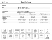
Views System Information Computer model Processor L3 cache Chipset Specifications Inspiron 5548 • 5th Generation Intel Core i5 ULV • 5th Generation Intel Core i7 ULV 4 MB Integrated in processor Dimensions and Weight System Information Memory Ports and Connectors Communications Video Audio Storage Media-Card Reader Display Keyboard Camera Touch Pad Battery Power Adapter Computer Environment
Views System Information Computer model Processor L3 cache Chipset Specifications Inspiron 5548 • 5th Generation Intel Core i5 ULV • 5th Generation Intel Core i7 ULV 4 MB Integrated in processor Dimensions and Weight System Information Memory Ports and Connectors Communications Video Audio Storage Media-Card Reader Display Keyboard Camera Touch Pad Battery Power Adapter Computer Environment

Specifications
Page 10
Views Ports and Connectors External: Network USB HDMI Audio Internal: M.2 Specifications One RJ45 port • One USB 2.0 port • Two USB 3.0 ports One HDMI port One headset port One M.2-2230 slot for WLAN, Bluetooth, and Intel WiDi (optional) Dimensions and Weight System Information Memory Ports and Connectors Communications Video Audio Storage Media-Card Reader Display Keyboard Camera Touch Pad Battery Power Adapter Computer Environment
Views Ports and Connectors External: Network USB HDMI Audio Internal: M.2 Specifications One RJ45 port • One USB 2.0 port • Two USB 3.0 ports One HDMI port One headset port One M.2-2230 slot for WLAN, Bluetooth, and Intel WiDi (optional) Dimensions and Weight System Information Memory Ports and Connectors Communications Video Audio Storage Media-Card Reader Display Keyboard Camera Touch Pad Battery Power Adapter Computer Environment

Specifications
Page 11
Views Communications Ethernet Wireless Specifications 10/100 Mbps Ethernet controller integrated on system board • Wi-Fi 802.11ac/b/g/n • Bluetooth 4.0 • Intel WiDi (optional) Dimensions and Weight System Information Memory Ports and Connectors Communications Video Audio Storage Media-Card Reader Display Keyboard Camera Touch Pad Battery Power Adapter Computer Environment
Views Communications Ethernet Wireless Specifications 10/100 Mbps Ethernet controller integrated on system board • Wi-Fi 802.11ac/b/g/n • Bluetooth 4.0 • Intel WiDi (optional) Dimensions and Weight System Information Memory Ports and Connectors Communications Video Audio Storage Media-Card Reader Display Keyboard Camera Touch Pad Battery Power Adapter Computer Environment
Specifications
Page 16
... (14.43 in) 225.06 mm (8.86 in) 344.16 mm (13.55 in) 366.63 mm (14.43 in) Dimensions and Weight System Information Memory Ports and Connectors Communications Video Audio Storage Media-Card Reader Display Keyboard Camera Touch Pad Battery Power Adapter Computer Environment
... (14.43 in) 225.06 mm (8.86 in) 344.16 mm (13.55 in) 366.63 mm (14.43 in) Dimensions and Weight System Information Memory Ports and Connectors Communications Video Audio Storage Media-Card Reader Display Keyboard Camera Touch Pad Battery Power Adapter Computer Environment

Specifications
Page 17
... define the primary behavior of the shortcut keys by changing Function Key Behavior in BIOS setup program. NOTE: You can be used to type alternate characters or to perform secondary functions. Dimensions and Weight System Information Memory Ports and Connectors Communications Video Audio Storage Media-Card Reader Display Keyboard Camera Touch Pad Battery Power Adapter Computer Environment Views Keyboard Type Shortcut keys Specifications • Standard keyboard • Backlit keyboard (optional) Some keys on your keyboard have two symbols on them. To perform secondary...
... define the primary behavior of the shortcut keys by changing Function Key Behavior in BIOS setup program. NOTE: You can be used to type alternate characters or to perform secondary functions. Dimensions and Weight System Information Memory Ports and Connectors Communications Video Audio Storage Media-Card Reader Display Keyboard Camera Touch Pad Battery Power Adapter Computer Environment Views Keyboard Type Shortcut keys Specifications • Standard keyboard • Backlit keyboard (optional) Some keys on your keyboard have two symbols on them. To perform secondary...

Service Manual
Page 4
Removing the Memory Modules 21 Prerequisites...21 Procedure...22 Replacing the Memory Modules 23 Procedure...23 Post-requisites 23 Removing the Wireless Card 24 Prerequisites...24 Procedure...24 Replacing the Wireless Card 26 Procedure...26 Post-requisites 26 Removing the Fan 27 Prerequisites...27 Procedure...27 Replacing the Fan 30 Procedure...30 Post-requisites 30 Removing the Keyboard 31 Prerequisites...31 Procedure...31 Replacing the Keyboard 34 Procedure...34 Folding the Keyboard Cables 34 Post-requisites 36
Removing the Memory Modules 21 Prerequisites...21 Procedure...22 Replacing the Memory Modules 23 Procedure...23 Post-requisites 23 Removing the Wireless Card 24 Prerequisites...24 Procedure...24 Replacing the Wireless Card 26 Procedure...26 Post-requisites 26 Removing the Fan 27 Prerequisites...27 Procedure...27 Replacing the Fan 30 Procedure...30 Post-requisites 30 Removing the Keyboard 31 Prerequisites...31 Procedure...31 Replacing the Keyboard 34 Procedure...34 Folding the Keyboard Cables 34 Post-requisites 36

Service Manual
Page 8
... electrical outlets. 4 Disconnect all cables such as keyboard, mouse, monitor, and so on the configuration you are using a different operating system, see the documentation of your computer, if applicable. NOTE: The images in this document may differ from your computer depending on , from your computer. 6 Remove any media card and optical disc from your operating system for shut-down . NOTE: If you ordered.
... electrical outlets. 4 Disconnect all cables such as keyboard, mouse, monitor, and so on the configuration you are using a different operating system, see the documentation of your computer, if applicable. NOTE: The images in this document may differ from your computer depending on , from your computer. 6 Remove any media card and optical disc from your operating system for shut-down . NOTE: If you ordered.

Service Manual
Page 9
... disconnect a network cable, first unplug the cable from your computer, ground yourself by your computer. When connecting cables, make sure that the work , periodically touch an unpainted metal surface to servicing that you finish working inside your computer and then unplug the cable from the media-card reader. After you must disengage before opening the computer cover or panels. See the safety instructions that shipped with locking tabs or...
... disconnect a network cable, first unplug the cable from your computer, ground yourself by your computer. When connecting cables, make sure that the work , periodically touch an unpainted metal surface to servicing that you finish working inside your computer and then unplug the cable from the media-card reader. After you must disengage before opening the computer cover or panels. See the safety instructions that shipped with locking tabs or...

Service Manual
Page 11
After Working Inside Your Computer CAUTION: Leaving stray or loose screws inside your computer may severely damage your computer. 1 Replace all screws and make sure that no stray screws remain inside your computer. 2 Connect any external devices, peripherals, and cables you removed before working on your computer. 3 Replace any media cards, discs, and any other part(s) that you removed before working on your computer. 4 Connect your computer and all attached devices to their electrical outlets. 5 Turn on your computer. 11
After Working Inside Your Computer CAUTION: Leaving stray or loose screws inside your computer may severely damage your computer. 1 Replace all screws and make sure that no stray screws remain inside your computer. 2 Connect any external devices, peripherals, and cables you removed before working on your computer. 3 Replace any media cards, discs, and any other part(s) that you removed before working on your computer. 4 Connect your computer and all attached devices to their electrical outlets. 5 Turn on your computer. 11

Service Manual
Page 15
... dell.com/regulatory_compliance. Prerequisites Remove the base cover. Removing the Battery WARNING: Before working inside your computer, read the safety information that secure the battery to the base frame. 2 Using the pull tab, slide and lift the battery off the base frame. 1 pull tab 3 battery 2 screws (4) 3 Turn the computer over, open the display, and press the power button for about 5 seconds to ground the system board. 15...
... dell.com/regulatory_compliance. Prerequisites Remove the base cover. Removing the Battery WARNING: Before working inside your computer, read the safety information that secure the battery to the base frame. 2 Using the pull tab, slide and lift the battery off the base frame. 1 pull tab 3 battery 2 screws (4) 3 Turn the computer over, open the display, and press the power button for about 5 seconds to ground the system board. 15...

Service Manual
Page 18
2 Using the pull tab, slide the hard-drive assembly out of the base frame. 1 pull tab 2 screws (4) 3 hard-drive assembly 3 Disconnect the hard-drive cable from the hard drive. 1 hard-drive assembly 2 hard-drive cable 4 Remove the screws that secure the hard-drive bracket to the hard drive. 18
2 Using the pull tab, slide the hard-drive assembly out of the base frame. 1 pull tab 2 screws (4) 3 hard-drive assembly 3 Disconnect the hard-drive cable from the hard drive. 1 hard-drive assembly 2 hard-drive cable 4 Remove the screws that secure the hard-drive bracket to the hard drive. 18
Service Manual
Page 20
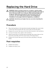
... the instructions in Before Working Inside Your Computer. Post-requisites 1 Replace the battery. 2 Replace the base cover. 20 Exercise care when handling the hard drive. For more safety best practices, see the Regulatory Compliance home page at dell.com/regulatory_compliance. Replacing the Hard Drive WARNING: Before working inside your computer, read the safety information that secure the hard-drive assembly to the hard drive. 4 Slide the hard drive in...
... the instructions in Before Working Inside Your Computer. Post-requisites 1 Replace the battery. 2 Replace the base cover. 20 Exercise care when handling the hard drive. For more safety best practices, see the Regulatory Compliance home page at dell.com/regulatory_compliance. Replacing the Hard Drive WARNING: Before working inside your computer, read the safety information that secure the hard-drive assembly to the hard drive. 4 Slide the hard drive in...

Service Manual
Page 21
After working inside your computer and follow the instructions in Before Working Inside Your Computer. For more safety best practices, see the Regulatory Compliance home page at dell.com/regulatory_compliance. Removing the Memory Modules WARNING: Before working inside your computer, read the safety information that shipped with your computer, follow the steps in After Working Inside Your Computer. Prerequisites 1 Remove the base cover. 2 Remove the battery. 21
After working inside your computer and follow the instructions in Before Working Inside Your Computer. For more safety best practices, see the Regulatory Compliance home page at dell.com/regulatory_compliance. Removing the Memory Modules WARNING: Before working inside your computer, read the safety information that shipped with your computer, follow the steps in After Working Inside Your Computer. Prerequisites 1 Remove the base cover. 2 Remove the battery. 21

Service Manual
Page 22
Procedure 1 Using your fingertips, pry apart the securing clips on each end of the memory-module slot until the memory module pops up. 1 memory-module slot 2 memory module 3 securing clips 2 Slide and remove the memory module from the memory-module slot. 22
Procedure 1 Using your fingertips, pry apart the securing clips on each end of the memory-module slot until the memory module pops up. 1 memory-module slot 2 memory module 3 securing clips 2 Slide and remove the memory module from the memory-module slot. 22

Service Manual
Page 23
... the notch on the memorymodule slot. 2 Slide the memory module firmly into the connector at dell.com/regulatory_compliance. NOTE: If you do not hear the click, remove the memory module and reinstall it clicks into place. After working inside your computer and follow the instructions in Before Working Inside Your Computer. Post-requisites 1 Replace the battery. 2 Replace the base cover. 23 For more safety...
... the notch on the memorymodule slot. 2 Slide the memory module firmly into the connector at dell.com/regulatory_compliance. NOTE: If you do not hear the click, remove the memory module and reinstall it clicks into place. After working inside your computer and follow the instructions in Before Working Inside Your Computer. Post-requisites 1 Replace the battery. 2 Replace the base cover. 23 For more safety...

Service Manual
Page 43
... computer, follow the steps in removing the hard drive. 4 Remove the fan. 5 Remove the keyboard. 6 Remove the base frame. 43 For more safety best practices, see the Regulatory Compliance home page at dell.com/regulatory_compliance. CAUTION: Removing the coin-cell battery resets the BIOS settings to step 3 in Before Working Inside Your Computer. After working inside your computer and follow the instructions in After Working Inside Your Computer.
... computer, follow the steps in removing the hard drive. 4 Remove the fan. 5 Remove the keyboard. 6 Remove the base frame. 43 For more safety best practices, see the Regulatory Compliance home page at dell.com/regulatory_compliance. CAUTION: Removing the coin-cell battery resets the BIOS settings to step 3 in Before Working Inside Your Computer. After working inside your computer and follow the instructions in After Working Inside Your Computer.

Service Manual
Page 61
... board. Prerequisites 1 Remove the base cover. 2 Remove the battery. 3 Follow the procedure from the system board, note the location of the connectors so that shipped with your computer and follow the instructions in removing the hard drive. 4 Remove the memory module(s). 5 Remove the wireless card. 6 Remove the fan. 7 Remove the keyboard. 8 Remove the base frame. 9 Remove the display assembly. 10 Remove the heat sink. Procedure 1 Disconnect the hard-drive cable from the system board. 61 NOTE: Replacing the system board removes any changes...
... board. Prerequisites 1 Remove the base cover. 2 Remove the battery. 3 Follow the procedure from the system board, note the location of the connectors so that shipped with your computer and follow the instructions in removing the hard drive. 4 Remove the memory module(s). 5 Remove the wireless card. 6 Remove the fan. 7 Remove the keyboard. 8 Remove the base frame. 9 Remove the display assembly. 10 Remove the heat sink. Procedure 1 Disconnect the hard-drive cable from the system board. 61 NOTE: Replacing the system board removes any changes...

Service Manual
Page 64
... You must enter the Service Tag in the BIOS setup program after you replace the system board. Replacing the System Board WARNING: Before working inside your computer, read the safety information that secure the system board to the BIOS using the BIOS setup program. For more safety best practices, see the Regulatory Compliance home page at dell.com/regulatory_compliance. Procedure CAUTION: Make sure that no cables are...
... You must enter the Service Tag in the BIOS setup program after you replace the system board. Replacing the System Board WARNING: Before working inside your computer, read the safety information that secure the system board to the BIOS using the BIOS setup program. For more safety best practices, see the Regulatory Compliance home page at dell.com/regulatory_compliance. Procedure CAUTION: Make sure that no cables are...

Service Manual
Page 76
... Accessing Windows Help Self-Help Options Windows 8.1 - Contacting Dell To contact Dell for sales, technical support, or customer service issues, see dell.com/contactdell. Windows 7 - Getting Help and Contacting Dell Self-Help Resources You can get information and help on Dell products and services using your computer, data backup, diagnostics, and so on See dell.com/support. Open the Search charm, type Help and Support in your country. 76 services Troubleshooting information, user manuals, setup instructions...
... Accessing Windows Help Self-Help Options Windows 8.1 - Contacting Dell To contact Dell for sales, technical support, or customer service issues, see dell.com/contactdell. Windows 7 - Getting Help and Contacting Dell Self-Help Resources You can get information and help on Dell products and services using your computer, data backup, diagnostics, and so on See dell.com/support. Open the Search charm, type Help and Support in your country. 76 services Troubleshooting information, user manuals, setup instructions...


