
Specifications
Page 2
Power adapter is connected and the battery is low or critical. 2 Hard-drive activity light Turns on when the computer reads from or writes to the hard drive. Amber light - Battery charge is being charged. Specifications Front Front 12 Left Views Right Base Display 1 Power and battery‑status light Indicates the power state and battery state of the computer. White light -
Power adapter is connected and the battery is low or critical. 2 Hard-drive activity light Turns on when the computer reads from or writes to the hard drive. Amber light - Battery charge is being charged. Specifications Front Front 12 Left Views Right Base Display 1 Power and battery‑status light Indicates the power state and battery state of the computer. White light -

Specifications
Page 7
Dimensions and Weight System Information Memory Ports and Connectors Communications Video Audio Storage Media-Card Reader Display Keyboard Camera Touch Pad Battery Power Adapter Computer Environment Views Dimensions and Weight Height: Touch screen (Inspiron 5542 only) Non-touch screen Width Depth Weight: Touch screen (Inspiron 5542 only) Non-touch screen Specifications 23.20 mm (0.91 in) 22.70 mm (0.89 in) 380.40 mm (14.98 in) 259 mm (10.20 in) 2.31 kg (5.09 lb) 2....
Dimensions and Weight System Information Memory Ports and Connectors Communications Video Audio Storage Media-Card Reader Display Keyboard Camera Touch Pad Battery Power Adapter Computer Environment Views Dimensions and Weight Height: Touch screen (Inspiron 5542 only) Non-touch screen Width Depth Weight: Touch screen (Inspiron 5542 only) Non-touch screen Specifications 23.20 mm (0.91 in) 22.70 mm (0.89 in) 380.40 mm (14.98 in) 259 mm (10.20 in) 2.31 kg (5.09 lb) 2....

Specifications
Page 10
Views Ports and Connectors External: Network USB HDMI Audio Internal: M.2 Specifications One RJ45 port • One USB 2.0 port • Two USB 3.0 ports One HDMI port One headset port One M.2-2230 slot for WLAN, Bluetooth, and Intel WiDi (optional) Dimensions and Weight System Information Memory Ports and Connectors Communications Video Audio Storage Media-Card Reader Display Keyboard Camera Touch Pad Battery Power Adapter Computer Environment
Views Ports and Connectors External: Network USB HDMI Audio Internal: M.2 Specifications One RJ45 port • One USB 2.0 port • Two USB 3.0 ports One HDMI port One headset port One M.2-2230 slot for WLAN, Bluetooth, and Intel WiDi (optional) Dimensions and Weight System Information Memory Ports and Connectors Communications Video Audio Storage Media-Card Reader Display Keyboard Camera Touch Pad Battery Power Adapter Computer Environment

Specifications
Page 11
Views Communications Ethernet Wireless Specifications 10/100 Mbps Ethernet controller integrated on system board • Wi-Fi 802.11b/g/n/ac • Bluetooth 4.0 • Intel WiDi (optional) • Miracast (Windows 8.1) Dimensions and Weight System Information Memory Ports and Connectors Communications Video Audio Storage Media-Card Reader Display Keyboard Camera Touch Pad Battery Power Adapter Computer Environment
Views Communications Ethernet Wireless Specifications 10/100 Mbps Ethernet controller integrated on system board • Wi-Fi 802.11b/g/n/ac • Bluetooth 4.0 • Intel WiDi (optional) • Miracast (Windows 8.1) Dimensions and Weight System Information Memory Ports and Connectors Communications Video Audio Storage Media-Card Reader Display Keyboard Camera Touch Pad Battery Power Adapter Computer Environment

Specifications
Page 16
... controlled using shortcut keys. 1366 x 768 0.252 mm Non-touch screen Touch screen (Inspiron 5542 only) 224.30 mm (8.83 in) 344.20 mm (13.55 in) 360 mm (14.17 in) 225.06 mm (8.86 in) 344.23 mm (13.55 in) 366.63 mm (14.43 in) Dimensions and Weight System Information Memory Ports and Connectors Communications Video Audio Storage Media-Card Reader Display Keyboard Camera Touch Pad Battery Power Adapter...
... controlled using shortcut keys. 1366 x 768 0.252 mm Non-touch screen Touch screen (Inspiron 5542 only) 224.30 mm (8.83 in) 344.20 mm (13.55 in) 360 mm (14.17 in) 225.06 mm (8.86 in) 344.23 mm (13.55 in) 366.63 mm (14.43 in) Dimensions and Weight System Information Memory Ports and Connectors Communications Video Audio Storage Media-Card Reader Display Keyboard Camera Touch Pad Battery Power Adapter...

Specifications
Page 17
... keys by changing Function Key Behavior in BIOS setup program. NOTE: You can be used to type alternate characters or to perform secondary functions. To perform secondary functions, press Fn and the desired key. Dimensions and Weight System Information Memory Ports and Connectors Communications Video Audio Storage Media-Card Reader Display Keyboard Camera Touch Pad Battery Power Adapter Computer Environment To type the alternate character, press Shift and the desired key. Views Keyboard Type Shortcut keys Specifications Standard keyboard Some keys on your keyboard...
... keys by changing Function Key Behavior in BIOS setup program. NOTE: You can be used to type alternate characters or to perform secondary functions. To perform secondary functions, press Fn and the desired key. Dimensions and Weight System Information Memory Ports and Connectors Communications Video Audio Storage Media-Card Reader Display Keyboard Camera Touch Pad Battery Power Adapter Computer Environment To type the alternate character, press Shift and the desired key. Views Keyboard Type Shortcut keys Specifications Standard keyboard Some keys on your keyboard...

Service Manual
Page 4
Removing the Memory Modules 22 Prerequisites...22 Procedure...23 Replacing the Memory Modules 24 Procedure...24 Post-requisites 24 Removing the Wireless Card 25 Prerequisites...25 Procedure...25 Replacing the Wireless Card 27 Procedure...27 Post-requisites 27 Removing the Fan 28 Prerequisites...28 Procedure...28 Replacing the Fan 31 Procedure...31 Post-requisites 31 Removing the Keyboard 32 Prerequisites...32 Procedure...32 Replacing the Keyboard 35 Procedure...35 Folding the Keyboard Cables 35 Post-requisites 37
Removing the Memory Modules 22 Prerequisites...22 Procedure...23 Replacing the Memory Modules 24 Procedure...24 Post-requisites 24 Removing the Wireless Card 25 Prerequisites...25 Procedure...25 Replacing the Wireless Card 27 Procedure...27 Post-requisites 27 Removing the Fan 28 Prerequisites...28 Procedure...28 Replacing the Fan 31 Procedure...31 Post-requisites 31 Removing the Keyboard 32 Prerequisites...32 Procedure...32 Replacing the Keyboard 35 Procedure...35 Folding the Keyboard Cables 35 Post-requisites 37

Service Manual
Page 9
... 1 Save and close all open files and exit all attached devices and peripherals, such as keyboard, mouse, monitor, and so on the configuration you are using a different operating system, see the documentation of your personal safety. 9 Windows 8.1: On the Start screen, click or tap the power icon → Shut down your computer, if applicable. NOTE: If you ordered. Safety Instructions Use the following safety guidelines...
... 1 Save and close all open files and exit all attached devices and peripherals, such as keyboard, mouse, monitor, and so on the configuration you are using a different operating system, see the documentation of your personal safety. 9 Windows 8.1: On the Start screen, click or tap the power icon → Shut down your computer, if applicable. NOTE: If you ordered. Safety Instructions Use the following safety guidelines...
Service Manual
Page 10
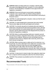
... then unplug the cable from the media-card reader. Some cables have connectors with locking tabs or thumb-screws that the work , periodically touch an unpainted metal surface to the power source. CAUTION: You should only perform troubleshooting and repairs as the metal at dell.com/ regulatory_compliance. WARNING: Disconnect all covers, panels, and screws before connecting to dissipate static electricity, which could harm internal components. CAUTION...
... then unplug the cable from the media-card reader. Some cables have connectors with locking tabs or thumb-screws that the work , periodically touch an unpainted metal surface to the power source. CAUTION: You should only perform troubleshooting and repairs as the metal at dell.com/ regulatory_compliance. WARNING: Disconnect all covers, panels, and screws before connecting to dissipate static electricity, which could harm internal components. CAUTION...

Service Manual
Page 12
After Working Inside Your Computer CAUTION: Leaving stray or loose screws inside your computer may severely damage your computer. 1 Replace all screws and make sure that no stray screws remain inside your computer. 2 Connect any external devices, peripherals, and cables you removed before working on your computer. 3 Replace any media cards, discs, and any other part(s) that you removed before working on your computer. 4 Connect your computer and all attached devices to their electrical outlets. 5 Turn on your computer. 12
After Working Inside Your Computer CAUTION: Leaving stray or loose screws inside your computer may severely damage your computer. 1 Replace all screws and make sure that no stray screws remain inside your computer. 2 Connect any external devices, peripherals, and cables you removed before working on your computer. 3 Replace any media cards, discs, and any other part(s) that you removed before working on your computer. 4 Connect your computer and all attached devices to their electrical outlets. 5 Turn on your computer. 12

Service Manual
Page 16
... Compliance home page at dell.com/regulatory_compliance. Prerequisites Remove the base cover. Removing the Battery WARNING: Before working inside your computer, read the safety information that secure the battery to the base frame. 2 Using the pull tab, slide and lift the battery off the base frame. 1 pull tab 3 battery 2 screws (4) 3 Turn the computer over, open the display, and press the power button for about 5 seconds...
... Compliance home page at dell.com/regulatory_compliance. Prerequisites Remove the base cover. Removing the Battery WARNING: Before working inside your computer, read the safety information that secure the battery to the base frame. 2 Using the pull tab, slide and lift the battery off the base frame. 1 pull tab 3 battery 2 screws (4) 3 Turn the computer over, open the display, and press the power button for about 5 seconds...

Service Manual
Page 19
2 Using the pull tab, slide the hard-drive assembly out of the base frame. 1 pull tab 2 screws (4) 3 hard-drive assembly 3 Disconnect the hard-drive cable from the hard drive. 1 hard-drive assembly 2 hard-drive cable 4 Remove the screws that secure the hard-drive bracket to the hard drive. 19
2 Using the pull tab, slide the hard-drive assembly out of the base frame. 1 pull tab 2 screws (4) 3 hard-drive assembly 3 Disconnect the hard-drive cable from the hard drive. 1 hard-drive assembly 2 hard-drive cable 4 Remove the screws that secure the hard-drive bracket to the hard drive. 19

Service Manual
Page 21
... screws that secure the hard-drive bracket to the hard drive. 3 Connect the hard-drive cable to the hard drive. 4 Slide the hard drive in the base frame and align the screw holes on the hard drive. 2 Replace the screws that secure the hard-drive assembly to the base frame. CAUTION: Hard drives are fragile. Post-requisites 1 Replace the battery. 2 Replace the base cover. 21 Procedure 1 Place the hard drive in After Working Inside Your Computer...
... screws that secure the hard-drive bracket to the hard drive. 3 Connect the hard-drive cable to the hard drive. 4 Slide the hard drive in the base frame and align the screw holes on the hard drive. 2 Replace the screws that secure the hard-drive assembly to the base frame. CAUTION: Hard drives are fragile. Post-requisites 1 Replace the battery. 2 Replace the base cover. 21 Procedure 1 Place the hard drive in After Working Inside Your Computer...

Service Manual
Page 22
Removing the Memory Modules WARNING: Before working inside your computer, read the safety information that shipped with your computer, follow the steps in After Working Inside Your Computer. For more safety best practices, see the Regulatory Compliance home page at dell.com/regulatory_compliance. Prerequisites 1 Remove the base cover. 2 Remove the battery. 22 After working inside your computer and follow the instructions in Before Working Inside Your Computer.
Removing the Memory Modules WARNING: Before working inside your computer, read the safety information that shipped with your computer, follow the steps in After Working Inside Your Computer. For more safety best practices, see the Regulatory Compliance home page at dell.com/regulatory_compliance. Prerequisites 1 Remove the base cover. 2 Remove the battery. 22 After working inside your computer and follow the instructions in Before Working Inside Your Computer.

Service Manual
Page 23
Procedure 1 Using your fingertips, pry apart the securing clips on each end of the memory-module slot until the memory module pops up. 1 memory-module slot 2 memory module 3 securing clips 2 Slide and remove the memory module from the memory-module slot. 23
Procedure 1 Using your fingertips, pry apart the securing clips on each end of the memory-module slot until the memory module pops up. 1 memory-module slot 2 memory module 3 securing clips 2 Slide and remove the memory module from the memory-module slot. 23

Service Manual
Page 24
NOTE: If you do not hear the click, remove the memory module and reinstall it clicks into the connector at dell.com/regulatory_compliance. After working inside your computer and follow the instructions in Before Working Inside Your Computer. Post-requisites 1 Replace the battery. 2 Replace the base cover. 24 Replacing the Memory Modules WARNING: Before working inside your computer, read the safety information that shipped with the...
NOTE: If you do not hear the click, remove the memory module and reinstall it clicks into the connector at dell.com/regulatory_compliance. After working inside your computer and follow the instructions in Before Working Inside Your Computer. Post-requisites 1 Replace the battery. 2 Replace the base cover. 24 Replacing the Memory Modules WARNING: Before working inside your computer, read the safety information that shipped with the...

Service Manual
Page 44
... BIOS settings before removing the coin-cell battery. After working inside your computer and follow the instructions in Before Working Inside Your Computer. CAUTION: Removing the coin-cell battery resets the BIOS settings to step 3 in removing the hard drive. 4 Remove the fan. 5 Remove the keyboard. 6 Remove the base frame. 44 It is recommended that shipped with your computer, follow the steps in After Working Inside Your Computer. Prerequisites 1 Remove the base cover. 2 Remove...
... BIOS settings before removing the coin-cell battery. After working inside your computer and follow the instructions in Before Working Inside Your Computer. CAUTION: Removing the coin-cell battery resets the BIOS settings to step 3 in removing the hard drive. 4 Remove the fan. 5 Remove the keyboard. 6 Remove the base frame. 44 It is recommended that shipped with your computer, follow the steps in After Working Inside Your Computer. Prerequisites 1 Remove the base cover. 2 Remove...
Service Manual
Page 62
... replace the system board. NOTE: Before disconnecting the cables from the system board. 62 For more safety best practices, see the Regulatory Compliance home page at dell.com/regulatory_compliance. Procedure 1 Disconnect the hard-drive cable from the system board, note the location of the connectors so that shipped with your computer and follow the instructions in removing the hard drive. 4 Remove the memory module(s). 5 Remove the wireless card. 6 Remove the fan. 7 Remove the keyboard. 8 Remove...
... replace the system board. NOTE: Before disconnecting the cables from the system board. 62 For more safety best practices, see the Regulatory Compliance home page at dell.com/regulatory_compliance. Procedure 1 Disconnect the hard-drive cable from the system board, note the location of the connectors so that shipped with your computer and follow the instructions in removing the hard drive. 4 Remove the memory module(s). 5 Remove the wireless card. 6 Remove the fan. 7 Remove the keyboard. 8 Remove...

Service Manual
Page 65
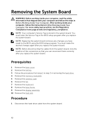
... the BIOS using the BIOS setup program. NOTE: Replacing the system board removes any changes you replace the system board. NOTE: Your computer's Service Tag is stored in Before Working Inside Your Computer. You must make the desired changes again after you have made to the palm-rest assembly. 65 Procedure CAUTION: Make sure that no cables are placed under the system board. 1 Slide the ports into the slots...
... the BIOS using the BIOS setup program. NOTE: Replacing the system board removes any changes you replace the system board. NOTE: Your computer's Service Tag is stored in Before Working Inside Your Computer. You must make the desired changes again after you have made to the palm-rest assembly. 65 Procedure CAUTION: Make sure that no cables are placed under the system board. 1 Slide the ports into the slots...

Service Manual
Page 92
... charm, type Help and Support in your operating system, setting up and using these online self-help blogs, drivers, software updates, and so on . Contacting Dell To contact Dell for sales, technical support, or customer service issues, see dell.com/contactdell. See Me and My Dell at dell.com/ support/manuals. Click Start → Help and Support. Windows 7 - services Troubleshooting information, user manuals, setup instructions, product specifications, technical help resources: Self-Help Information Accessing Windows Help Self-Help Options Windows 8.1 - Information...
... charm, type Help and Support in your operating system, setting up and using these online self-help blogs, drivers, software updates, and so on . Contacting Dell To contact Dell for sales, technical support, or customer service issues, see dell.com/contactdell. See Me and My Dell at dell.com/ support/manuals. Click Start → Help and Support. Windows 7 - services Troubleshooting information, user manuals, setup instructions, product specifications, technical help resources: Self-Help Information Accessing Windows Help Self-Help Options Windows 8.1 - Information...


