Specifications
Page 8
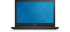
... • 4th generation Intel Core i7 Integrated in processor Inspiron 15-3543 • Intel Celeron • Intel Pentium • 5th generation Intel Core i3 ULV • 5th generation Intel Core i5 ULV • 5th generation Intel Core i7 ULV Integrated in processor Dimensions and Weight System Information Memory Ports and Connectors Communications Video Audio Storage Media-Card Reader Display Keyboard Camera Touch Pad Battery Power Adapter Computer Environment
... • 4th generation Intel Core i7 Integrated in processor Inspiron 15-3543 • Intel Celeron • Intel Pentium • 5th generation Intel Core i3 ULV • 5th generation Intel Core i5 ULV • 5th generation Intel Core i7 ULV Integrated in processor Dimensions and Weight System Information Memory Ports and Connectors Communications Video Audio Storage Media-Card Reader Display Keyboard Camera Touch Pad Battery Power Adapter Computer Environment
Specifications
Page 12
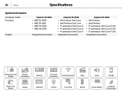
Views Specifications Video Controller: Inspiron 15-3541 Inspiron 15-3542 Inspiron 15-3543 Memory Integrated • AMD Radeon R4 Graphics for AMD A6 Quad Core • AMD Radeon R3 Graphics ..., and Intel Core i7 Shared system memory Discrete AMD Radeon HD R5 M230 • nVidia 820M • nVidia 840M • nVidia 820M • nVidia 840M • 1 GB DDR3L • 2 GB DDR3L Dimensions and Weight System Information Memory Ports and Connectors Communications Video Audio Storage Media-Card Reader Display Keyboard Camera Touch Pad Battery Power Adapter Computer Environment
Views Specifications Video Controller: Inspiron 15-3541 Inspiron 15-3542 Inspiron 15-3543 Memory Integrated • AMD Radeon R4 Graphics for AMD A6 Quad Core • AMD Radeon R3 Graphics ..., and Intel Core i7 Shared system memory Discrete AMD Radeon HD R5 M230 • nVidia 820M • nVidia 840M • nVidia 820M • nVidia 840M • 1 GB DDR3L • 2 GB DDR3L Dimensions and Weight System Information Memory Ports and Connectors Communications Video Audio Storage Media-Card Reader Display Keyboard Camera Touch Pad Battery Power Adapter Computer Environment
Specifications
Page 13
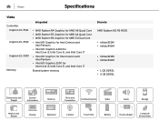
... and Weight System Information Memory Ports and Connectors Communications Video Audio Storage Media-Card Reader Display Keyboard Camera Touch Pad Battery Power Adapter Computer Environment Views Audio Controller: Intel AMD Speakers Speaker output: Average Peak Microphone Volume controls Specifications Realtek ALC3234 with Waves MaxxVoice Realtek ALC3223 with Waves MaxxVoice Two 2 W 2.5 W Digital microphone Program menus and keyboard media-control shortcut keys. To learn about your computer keyboard shortcut keys, see the Quick Start Guide at dell.com/support/manuals.
... and Weight System Information Memory Ports and Connectors Communications Video Audio Storage Media-Card Reader Display Keyboard Camera Touch Pad Battery Power Adapter Computer Environment Views Audio Controller: Intel AMD Speakers Speaker output: Average Peak Microphone Volume controls Specifications Realtek ALC3234 with Waves MaxxVoice Realtek ALC3223 with Waves MaxxVoice Two 2 W 2.5 W Digital microphone Program menus and keyboard media-control shortcut keys. To learn about your computer keyboard shortcut keys, see the Quick Start Guide at dell.com/support/manuals.
Specifications
Page 16
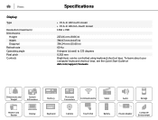
... x 768 225.06 mm (8.86 in) 366.63 mm (14.43 in) 396.24 mm (15.60 in) 60 Hz 0 degree (closed) to 135 degrees 0.252 mm Brightness can be controlled using keyboard shortcut keys. Dimensions and Weight System Information Memory Ports and Connectors Communications Video Audio Storage Media-Card Reader Display Keyboard Camera Touch Pad Battery Power Adapter Computer Environment To learn about your computer keyboard shortcut keys, see the Quick Start Guide at dell.com/support/manuals.
... x 768 225.06 mm (8.86 in) 366.63 mm (14.43 in) 396.24 mm (15.60 in) 60 Hz 0 degree (closed) to 135 degrees 0.252 mm Brightness can be controlled using keyboard shortcut keys. Dimensions and Weight System Information Memory Ports and Connectors Communications Video Audio Storage Media-Card Reader Display Keyboard Camera Touch Pad Battery Power Adapter Computer Environment To learn about your computer keyboard shortcut keys, see the Quick Start Guide at dell.com/support/manuals.

Specifications
Page 17
...to perform secondary functions. These keys can define the primary behavior of the shortcut keys by changing Function Key Behavior in BIOS setup program. To type the alternate character, press Shift and the desired key. Views Keyboard Type Shortcut keys Specifications • Standard keyboard • Backlit keyboard (optional) Some keys on your keyboard have two symbols on them. Dimensions and Weight System Information Memory Ports and Connectors Communications Video Audio Storage Media-Card Reader Display Keyboard Camera Touch Pad Battery Power Adapter Computer Environment...
...to perform secondary functions. These keys can define the primary behavior of the shortcut keys by changing Function Key Behavior in BIOS setup program. To type the alternate character, press Shift and the desired key. Views Keyboard Type Shortcut keys Specifications • Standard keyboard • Backlit keyboard (optional) Some keys on your keyboard have two symbols on them. Dimensions and Weight System Information Memory Ports and Connectors Communications Video Audio Storage Media-Card Reader Display Keyboard Camera Touch Pad Battery Power Adapter Computer Environment...

Service Manual
Page 4
Removing the Hard Drive 21 Prerequisites...21 Procedure...21 Replacing the Hard Drive 23 Procedure...23 Post-requisites 23 Removing the Memory Module 24 Prerequisites...24 Procedure...24 Replacing the Memory Module 26 Procedure...26 Post-requisites 27 Removing the Wireless Card 28 Prerequisites...28 Procedure...28 Replacing the Wireless Card 30 Procedure...30 Post-requisites 30 Removing the Keyboard 31 Prerequisites...31 Procedure...31 Replacing the Keyboard 34 Procedure...34 Folding the Keyboard Cables 34 Post-requisites 38
Removing the Hard Drive 21 Prerequisites...21 Procedure...21 Replacing the Hard Drive 23 Procedure...23 Post-requisites 23 Removing the Memory Module 24 Prerequisites...24 Procedure...24 Replacing the Memory Module 26 Procedure...26 Post-requisites 27 Removing the Wireless Card 28 Prerequisites...28 Procedure...28 Replacing the Wireless Card 30 Procedure...30 Post-requisites 30 Removing the Keyboard 31 Prerequisites...31 Procedure...31 Replacing the Keyboard 34 Procedure...34 Folding the Keyboard Cables 34 Post-requisites 38

Service Manual
Page 10
... avoid touching pins and contacts. Safety Instructions Use the following safety guidelines to protect your computer from your computer. 5 Disconnect all cables such as keyboard, mouse, monitor, and so on the configuration you ordered. NOTE: If you are using a different operating system, see the documentation of your operating system for shut-down your personal safety. 10 Windows 8.1: On the Start screen, click or tap the power...
... avoid touching pins and contacts. Safety Instructions Use the following safety guidelines to protect your computer from your computer. 5 Disconnect all cables such as keyboard, mouse, monitor, and so on the configuration you ordered. NOTE: If you are using a different operating system, see the documentation of your operating system for shut-down your personal safety. 10 Windows 8.1: On the Start screen, click or tap the power...

Service Manual
Page 11
... Dell is flat and clean. Some cables have connectors with your warranty. When connecting cables, make sure that the work , periodically touch an unpainted metal surface to the power source. CAUTION: Press and eject any connector pins. WARNING: Disconnect all covers, panels, and screws before opening the computer cover or panels. CAUTION: Before touching anything inside your computer and then unplug the cable from the media-card reader...
... Dell is flat and clean. Some cables have connectors with your warranty. When connecting cables, make sure that the work , periodically touch an unpainted metal surface to the power source. CAUTION: Press and eject any connector pins. WARNING: Disconnect all covers, panels, and screws before opening the computer cover or panels. CAUTION: Before touching anything inside your computer and then unplug the cable from the media-card reader...

Service Manual
Page 13
After Working Inside Your Computer CAUTION: Leaving stray or loose screws inside your computer may severely damage your computer. 1 Replace all screws and make sure that no stray screws remain inside your computer. 2 Connect any external devices, peripherals, and cables you removed before working on your computer. 3 Replace any media cards, discs, and any other part(s) that you removed before working on your computer. 4 Connect your computer and all attached devices to their electrical outlets. 5 Turn on your computer. 13
After Working Inside Your Computer CAUTION: Leaving stray or loose screws inside your computer may severely damage your computer. 1 Replace all screws and make sure that no stray screws remain inside your computer. 2 Connect any external devices, peripherals, and cables you removed before working on your computer. 3 Replace any media cards, discs, and any other part(s) that you removed before working on your computer. 4 Connect your computer and all attached devices to their electrical outlets. 5 Turn on your computer. 13

Service Manual
Page 24
... After Working Inside Your Computer. Prerequisites 1 Remove the battery. 2 Remove the base cover. Removing the Memory Module WARNING: Before working inside your computer, read the safety information that shipped with your computer and follow the instructions in Before Working Inside Your Computer. For more safety best practices, see the Regulatory Compliance home page at dell.com/regulatory_compliance. Procedure 1 Using your fingertips, pry apart the...
... After Working Inside Your Computer. Prerequisites 1 Remove the battery. 2 Remove the base cover. Removing the Memory Module WARNING: Before working inside your computer, read the safety information that shipped with your computer and follow the instructions in Before Working Inside Your Computer. For more safety best practices, see the Regulatory Compliance home page at dell.com/regulatory_compliance. Procedure 1 Using your fingertips, pry apart the...

Service Manual
Page 27
NOTE: If you do not hear the click, remove the memory module and reinstall it clicks into the slot at an angle and press the memory module down until it . 1 memory module 3 notch 5 memory-module slot Post-requisites 1 Replace the base cover. 2 Replace the battery. 2 securing clips (2) 4 tab 27 2 Slide the memory module into place.
NOTE: If you do not hear the click, remove the memory module and reinstall it clicks into the slot at an angle and press the memory module down until it . 1 memory module 3 notch 5 memory-module slot Post-requisites 1 Replace the base cover. 2 Replace the battery. 2 securing clips (2) 4 tab 27 2 Slide the memory module into place.

Service Manual
Page 61
Procedure Using a plastic scribe, gently pry out the coin-cell battery out of the battery socket on the system board. 61 CAUTION: Removing the coin-cell battery resets the BIOS settings to step 7 in After Working Inside Your Computer. It is recommended that shipped with your computer and follow the instructions in "Removing the Palm Rest". Prerequisites 1 Remove the battery. 2 Remove the base cover. 3 Follow the procedure...
Procedure Using a plastic scribe, gently pry out the coin-cell battery out of the battery socket on the system board. 61 CAUTION: Removing the coin-cell battery resets the BIOS settings to step 7 in After Working Inside Your Computer. It is recommended that shipped with your computer and follow the instructions in "Removing the Palm Rest". Prerequisites 1 Remove the battery. 2 Remove the base cover. 3 Follow the procedure...
Service Manual
Page 70
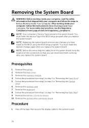
... BIOS using the BIOS setup program. Prerequisites 1 Remove the battery. 2 Remove the base cover. 3 Remove the memory module. 4 Follow the procedure from step 1 to step 3 in "Removing the Hard Drive". 5 Follow the procedure from step 1 to step 2 in "Removing the Optical Drive". 6 Remove the wireless card. 7 Remove the keyboard. 8 Follow the procedure from the system board, note the location of the connectors so that secures the display cable to step 7 in "Removing the Palm Rest". 9 Remove the battery...
... BIOS using the BIOS setup program. Prerequisites 1 Remove the battery. 2 Remove the base cover. 3 Remove the memory module. 4 Follow the procedure from step 1 to step 3 in "Removing the Hard Drive". 5 Follow the procedure from step 1 to step 2 in "Removing the Optical Drive". 6 Remove the wireless card. 7 Remove the keyboard. 8 Follow the procedure from the system board, note the location of the connectors so that secures the display cable to step 7 in "Removing the Palm Rest". 9 Remove the battery...
Service Manual
Page 73
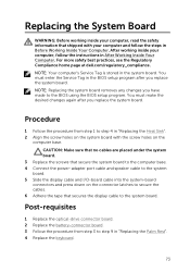
... the instructions in Before Working Inside Your Computer. Post-requisites 1 Replace the optical-drive connector board. 2 Replace the battery-connector board. 3 Follow the procedure from step 1 to step 9 in the BIOS setup program after you have made to the system board. CAUTION: Make sure that no cables are placed under the system board. 3 Replace the screws that secure the system board to the computer base. 4 Connect the power-adapter port cable...
... the instructions in Before Working Inside Your Computer. Post-requisites 1 Replace the optical-drive connector board. 2 Replace the battery-connector board. 3 Follow the procedure from step 1 to step 9 in the BIOS setup program after you have made to the system board. CAUTION: Make sure that no cables are placed under the system board. 3 Replace the screws that secure the system board to the computer base. 4 Connect the power-adapter port cable...

Service Manual
Page 84
... dell.com/regulatory_compliance. After working inside your computer, read the safety information that shipped with non-touch screen display. 1 Remove the base cover. 2 Remove the battery. 3 Follow the procedure from step 1 to step 3 in "Removing the Hard Drive". 4 Follow the procedure from step 1 to step 2 in "Removing the Optical Drive". 5 Remove the keyboard. 6 Follow the procedure from step 1 to step 7 in "Removing the Palm Rest". 7 Remove the power-adapter port. 8 Remove the display...
... dell.com/regulatory_compliance. After working inside your computer, read the safety information that shipped with non-touch screen display. 1 Remove the base cover. 2 Remove the battery. 3 Follow the procedure from step 1 to step 3 in "Removing the Hard Drive". 4 Follow the procedure from step 1 to step 2 in "Removing the Optical Drive". 5 Remove the keyboard. 6 Follow the procedure from step 1 to step 7 in "Removing the Palm Rest". 7 Remove the power-adapter port. 8 Remove the display...

Service Manual
Page 87
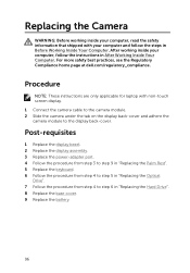
...-touch screen display. 1 Remove the battery. 2 Remove the base cover. 3 Follow the procedure from step 1 to step 3 in "Removing the Hard Drive". 4 Follow the procedure from step 1 to step 2 in "Removing the Optical Drive". 5 Remove the keyboard. 6 Follow the procedure from step 1 to the display backcover. 87 Prerequisites NOTE: These instructions are only applicable for laptop with your computer, follow the steps in "Removing the Palm Rest". 7 Remove the power-adapter port. 8 Remove...
...-touch screen display. 1 Remove the battery. 2 Remove the base cover. 3 Follow the procedure from step 1 to step 3 in "Removing the Hard Drive". 4 Follow the procedure from step 1 to step 2 in "Removing the Optical Drive". 5 Remove the keyboard. 6 Follow the procedure from step 1 to the display backcover. 87 Prerequisites NOTE: These instructions are only applicable for laptop with your computer, follow the steps in "Removing the Palm Rest". 7 Remove the power-adapter port. 8 Remove...

Service Manual
Page 90
... page at dell.com/regulatory_compliance. Replacing the Display Panel WARNING: Before working inside your computer, read the safety information that shipped with the screw holes on the display back-cover. 5 Replace the screws that secure the display panel to step 6 in "Replacing the Hard Drive". 8 Replace the base cover. 9 Replace the battery. 90 Procedure NOTE: These instructions are only applicable for laptop with non-touch screen display. 1 Connect the display cable to the display panel and press...
... page at dell.com/regulatory_compliance. Replacing the Display Panel WARNING: Before working inside your computer, read the safety information that shipped with the screw holes on the display back-cover. 5 Replace the screws that secure the display panel to step 6 in "Replacing the Hard Drive". 8 Replace the base cover. 9 Replace the battery. 90 Procedure NOTE: These instructions are only applicable for laptop with non-touch screen display. 1 Connect the display cable to the display panel and press...

Service Manual
Page 91
... "Removing the Palm Rest". 7 Remove the power-adapter port. 8 Remove the display assembly. 9 Remove the display bezel. After working inside your computer, follow the steps in Before Working Inside Your Computer. Procedure 1 Remove the screws that shipped with non-touch screen display. 1 Remove the battery. 2 Remove the base cover. 3 Follow the procedure from step 1 to step 3 in "Removing the Hard Drive". 4 Follow the procedure from step 1 to step 2 in "Removing the Optical Drive". 5 Remove the keyboard...
... "Removing the Palm Rest". 7 Remove the power-adapter port. 8 Remove the display assembly. 9 Remove the display bezel. After working inside your computer, follow the steps in Before Working Inside Your Computer. Procedure 1 Remove the screws that shipped with non-touch screen display. 1 Remove the battery. 2 Remove the base cover. 3 Follow the procedure from step 1 to step 3 in "Removing the Hard Drive". 4 Follow the procedure from step 1 to step 2 in "Removing the Optical Drive". 5 Remove the keyboard...

Service Manual
Page 94
... non-touch screen display. 1 Remove the battery. 2 Remove the base cover. 3 Follow the procedure from step 1 to step 3 in "Removing the Hard Drive". 4 Follow the procedure from step 1 to step 2 in "Removing the Optical Drive". 5 Remove the keyboard. 6 Follow the procedure from step 1 to step 3 in "Removing the Palm Rest". 7 Remove the power-adapter port. 8 Remove the display assembly. 9 Remove the display bezel. After working inside your computer and follow the instructions in After Working Inside...
... non-touch screen display. 1 Remove the battery. 2 Remove the base cover. 3 Follow the procedure from step 1 to step 3 in "Removing the Hard Drive". 4 Follow the procedure from step 1 to step 2 in "Removing the Optical Drive". 5 Remove the keyboard. 6 Follow the procedure from step 1 to step 3 in "Removing the Palm Rest". 7 Remove the power-adapter port. 8 Remove the display assembly. 9 Remove the display bezel. After working inside your computer and follow the instructions in After Working Inside...
Service Manual
Page 96
... your computer and follow the instructions in "Replacing the Hard Drive". 8 Replace the base cover. 9 Replace the battery. 96 For more safety best practices, see the Regulatory Compliance home page at dell.com/regulatory_compliance. Post-requisites 1 Replace the display bezel. 2 Replace the display assembly. 3 Replace the power-adapter port. 4 Follow the procedure from step 3 to step 9 in "Replacing the Palm Rest". 5 Replace the keyboard. 6 Follow the procedure from step 4 to...
... your computer and follow the instructions in "Replacing the Hard Drive". 8 Replace the base cover. 9 Replace the battery. 96 For more safety best practices, see the Regulatory Compliance home page at dell.com/regulatory_compliance. Post-requisites 1 Replace the display bezel. 2 Replace the display assembly. 3 Replace the power-adapter port. 4 Follow the procedure from step 3 to step 9 in "Replacing the Palm Rest". 5 Replace the keyboard. 6 Follow the procedure from step 4 to...


