Service Manual
Page 3
Contents 1 Before You Begin 9 Recommended Tools 9 Turning Off Your Computer 9 Before Working Inside Your Computer 10 2 Top Cover 13 Removing the Top Cover 13 Replacing the Top Cover 14 3 Battery 15 Removing the Battery 15 Replacing the Battery 16 4 Module Cover 17 Removing the Module Cover 17 Replacing the Module Cover 18 5 Optical Drive 19 Removing the Optical Drive 19 Contents 3
Contents 1 Before You Begin 9 Recommended Tools 9 Turning Off Your Computer 9 Before Working Inside Your Computer 10 2 Top Cover 13 Removing the Top Cover 13 Replacing the Top Cover 14 3 Battery 15 Removing the Battery 15 Replacing the Battery 16 4 Module Cover 17 Removing the Module Cover 17 Replacing the Module Cover 18 5 Optical Drive 19 Removing the Optical Drive 19 Contents 3

Service Manual
Page 7
19 Coin-Cell Battery 87 Removing the Coin-Cell Battery 87 Replacing the Coin-Cell Battery 88 20 Thermal Cooling Assembly 89 Removing the Thermal Cooling Assembly 89 Replacing the Thermal Cooling Assembly 90 21 Processor Module 91 Removing the Processor Module 91 Replacing the Processor Module 92 22 Hard-Drive Assembly 95 Removing the Hard-Drive Assembly 95 Replacing the Hard-Drive Assembly 97 23 I/O Board 99 Removing the I/O Board 99 Replacing the I/O Board 100 24 AC-Adapter Connector 101 Removing the AC-Adapter Connector 101 Contents 7
19 Coin-Cell Battery 87 Removing the Coin-Cell Battery 87 Replacing the Coin-Cell Battery 88 20 Thermal Cooling Assembly 89 Removing the Thermal Cooling Assembly 89 Replacing the Thermal Cooling Assembly 90 21 Processor Module 91 Removing the Processor Module 91 Replacing the Processor Module 92 22 Hard-Drive Assembly 95 Removing the Hard-Drive Assembly 95 Replacing the Hard-Drive Assembly 97 23 I/O Board 99 Removing the I/O Board 99 Replacing the I/O Board 100 24 AC-Adapter Connector 101 Removing the AC-Adapter Connector 101 Contents 7
Service Manual
Page 16
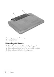
3 2 1 1 battery release latch 2 battery 3 battery lock latch Replacing the Battery 1 Follow the instructions in "Before You Begin" on page 9. 2 Slide the battery into the battery bay until it clicks into place. 3 Slide the battery lock latch to the lock position. 16 Battery
3 2 1 1 battery release latch 2 battery 3 battery lock latch Replacing the Battery 1 Follow the instructions in "Before You Begin" on page 9. 2 Slide the battery into the battery bay until it clicks into place. 3 Slide the battery lock latch to the lock position. 16 Battery
Service Manual
Page 18
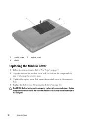
1 2 3 1 captive screw 2 module cover 3 tabs (2) Replacing the Module Cover 1 Follow the instructions in "Before You Begin" on page 9. 2 Align the tabs on the module cover with the slots on the computer base and gently snap the cover in damage to the computer base. 4 Replace the battery (see "Replacing the Battery" on the computer, replace all screws and ensure that secures the module cover to the computer. 18 Module Cover CAUTION: Before turning on page 16). Failure to do so may result in place. 3 Tighten the captive screw that no stray screws remain inside the computer.
1 2 3 1 captive screw 2 module cover 3 tabs (2) Replacing the Module Cover 1 Follow the instructions in "Before You Begin" on page 9. 2 Align the tabs on the module cover with the slots on the computer base and gently snap the cover in damage to the computer base. 4 Replace the battery (see "Replacing the Battery" on the computer, replace all screws and ensure that secures the module cover to the computer. 18 Module Cover CAUTION: Before turning on page 16). Failure to do so may result in place. 3 Tighten the captive screw that no stray screws remain inside the computer.
Service Manual
Page 21
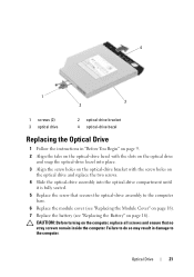
... screws and ensure that secures the optical-drive assembly to the computer base. 6 Replace the module cover (see "Replacing the Module Cover" on page 18). 7 Replace the battery (see "Replacing the Battery" on the optical drive and replace the two screws. 4 Slide the optical-drive assembly into place. 3 Align the screw holes on the optical-drive bracket...
... screws and ensure that secures the optical-drive assembly to the computer base. 6 Replace the module cover (see "Replacing the Module Cover" on page 18). 7 Replace the battery (see "Replacing the Battery" on the optical drive and replace the two screws. 4 Slide the optical-drive assembly into place. 3 Align the screw holes on the optical-drive bracket...
Service Manual
Page 25
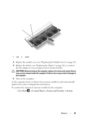
.... To confirm the amount of memory installed in damage to the computer. 6 Turn on the computer. 2 1 1 tab 2 notch 4 Replace the module cover (see "Replacing the Module Cover" on page 18). 5 Replace the battery (see "Replacing the Battery" on page 16), or connect the AC adapter to do so may result in the computer: Click Start ...
.... To confirm the amount of memory installed in damage to the computer. 6 Turn on the computer. 2 1 1 tab 2 notch 4 Replace the module cover (see "Replacing the Module Cover" on page 18). 5 Replace the battery (see "Replacing the Battery" on page 16), or connect the AC adapter to do so may result in the computer: Click Start ...
Service Manual
Page 27
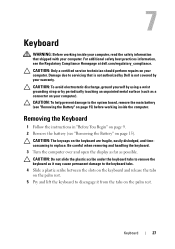
... yourself by using a wrist grounding strap or by your computer). Damage due to replace. Removing the Keyboard 1 Follow the instructions in "Before You Begin" on page 9. 2 Remove the battery (see "Removing the Battery" on your computer. CAUTION: Do not slide the plastic scribe under the keyboard ...) before working inside the computer. 7 Keyboard WARNING: Before working inside your computer, read the safety information that is not authorized by Dell is not covered by periodically touching an unpainted metal surface (such as a connector on page 15). CAUTION: The keycaps on the palm...
... yourself by using a wrist grounding strap or by your computer). Damage due to replace. Removing the Keyboard 1 Follow the instructions in "Before You Begin" on page 9. 2 Remove the battery (see "Removing the Battery" on your computer. CAUTION: Do not slide the plastic scribe under the keyboard ...) before working inside the computer. 7 Keyboard WARNING: Before working inside your computer, read the safety information that is not authorized by Dell is not covered by periodically touching an unpainted metal surface (such as a connector on page 15). CAUTION: The keycaps on the palm...
Service Manual
Page 30
6 Replace the battery (see "Replacing the Battery" on page 16). 30 Keyboard
6 Replace the battery (see "Replacing the Battery" on page 16). 30 Keyboard

Service Manual
Page 35
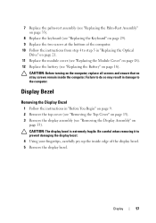
...-Rest Assembly 35 Failure to do so may result in "Replacing the Optical Drive" on page 21. 10 Replace the module cover (see "Replacing the Module Cover" on page 18). 11 Replace the battery (see "Replacing the Keyboard" on page 29). 8 Turn the computer over and replace the ten screws at the bottom of the computer. 9 Follow...
...-Rest Assembly 35 Failure to do so may result in "Replacing the Optical Drive" on page 21. 10 Replace the module cover (see "Replacing the Module Cover" on page 18). 11 Replace the battery (see "Replacing the Keyboard" on page 29). 8 Turn the computer over and replace the ten screws at the bottom of the computer. 9 Follow...
Service Manual
Page 38
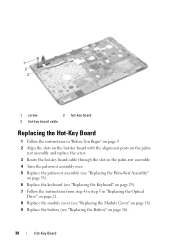
1 2 3 1 screw 2 hot-key board 3 hot-key board cable Replacing the Hot-Key Board 1 Follow the instructions in "Replacing the Optical Drive" on page 21. 8 Replace the module cover (see "Replacing the Module Cover" on page 18). 9 Replace the battery (see "Replacing the Battery" on the palm- rest assembly and replace the screw. 3 Route the hot-key board cable through the...
1 2 3 1 screw 2 hot-key board 3 hot-key board cable Replacing the Hot-Key Board 1 Follow the instructions in "Replacing the Optical Drive" on page 21. 8 Replace the module cover (see "Replacing the Module Cover" on page 18). 9 Replace the battery (see "Replacing the Battery" on the palm- rest assembly and replace the screw. 3 Route the hot-key board cable through the...
Service Manual
Page 43
Power Button Board 43 Failure to do so may result in damage to the computer. CAUTION: Before turning on page 15). 8 Replace the module cover (see "Replacing the Module Cover" on page 18). 9 Replace the battery (see "Removing the Battery" on the computer, replace all screws and ensure that no stray screws remain inside the computer.
Power Button Board 43 Failure to do so may result in damage to the computer. CAUTION: Before turning on page 15). 8 Replace the module cover (see "Replacing the Module Cover" on page 18). 9 Replace the battery (see "Removing the Battery" on the computer, replace all screws and ensure that no stray screws remain inside the computer.
Service Manual
Page 48
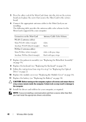
... so may result in damage to step 5 in "Replacing the Optical Drive" on page 21. 10 Replace the module cover (see "Replacing the Module Cover" on page 18). 11 Replace the battery (see "Replacing the Keyboard" on the computer, replace all screws and ensure that secures the Mini-Card to...Color Scheme white black white with gray stripe black with gray stripe 7 Replace the palm-rest assembly (see "Replacing the Palm-Rest Assembly" on page 35). 8 Replace the keyboard (see "Replacing the Battery" on the system board and replace the screw that no stray screws remain inside the computer. 5 Press...
... so may result in damage to step 5 in "Replacing the Optical Drive" on page 21. 10 Replace the module cover (see "Replacing the Module Cover" on page 18). 11 Replace the battery (see "Replacing the Keyboard" on the computer, replace all screws and ensure that secures the Mini-Card to...Color Scheme white black white with gray stripe black with gray stripe 7 Replace the palm-rest assembly (see "Replacing the Palm-Rest Assembly" on page 35). 8 Replace the keyboard (see "Replacing the Battery" on the system board and replace the screw that no stray screws remain inside the computer. 5 Press...
Service Manual
Page 51
CAUTION: Before turning on page 16). Failure to do so may result in damage to the computer. Thermal Fan 51 6 Replace the keyboard (see "Replacing the Keyboard" on page 29). 7 Replace the battery (see "Replacing the Battery" on the computer, replace all screws and ensure that no stray screws remain inside the computer.
CAUTION: Before turning on page 16). Failure to do so may result in damage to the computer. Thermal Fan 51 6 Replace the keyboard (see "Replacing the Keyboard" on page 29). 7 Replace the battery (see "Replacing the Battery" on the computer, replace all screws and ensure that no stray screws remain inside the computer.
Service Manual
Page 57
... Palm-Rest Assembly" on page 35). 8 Replace the keyboard (see "Replacing the Keyboard" on page 29). 9 Replace the two screws at the bottom of the display bezel. 5 Remove the display bezel. Display Bezel Removing the Display Bezel 1 Follow the instructions in... 3 Remove the display assembly (see "Replacing the Battery" on page 16). Failure to do so may result in "Replacing the Optical Drive" on page 21. 11 Replace the module cover (see "Replacing the Module Cover" on page 18). 12 Replace the battery (see "Removing the Display Assembly" on the computer, replace all screws and ensure that no...
... Palm-Rest Assembly" on page 35). 8 Replace the keyboard (see "Replacing the Keyboard" on page 29). 9 Replace the two screws at the bottom of the display bezel. 5 Remove the display bezel. Display Bezel Removing the Display Bezel 1 Follow the instructions in... 3 Remove the display assembly (see "Replacing the Battery" on page 16). Failure to do so may result in "Replacing the Optical Drive" on page 21. 11 Replace the module cover (see "Replacing the Module Cover" on page 18). 12 Replace the battery (see "Removing the Display Assembly" on the computer, replace all screws and ensure that no...
Service Manual
Page 67
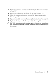
7 Replace the palm-rest assembly (see "Replacing the Palm-Rest Assembly" on page 35). 8 Replace the keyboard (see "Replacing the Keyboard" on page 29). 9 Follow the instructions from step 4 to the computer. Camera Module 67 Failure to do so may result in damage to step 5 in "Replacing the Optical Drive" on page 21. 10 Replace the module cover (see "Replacing the Module Cover" on page 18). 11 Replace the battery (see "Replacing the Battery" on the computer, replace all screws and ensure that no stray screws remain inside the computer. CAUTION: Before turning on page 16).
7 Replace the palm-rest assembly (see "Replacing the Palm-Rest Assembly" on page 35). 8 Replace the keyboard (see "Replacing the Keyboard" on page 29). 9 Follow the instructions from step 4 to the computer. Camera Module 67 Failure to do so may result in damage to step 5 in "Replacing the Optical Drive" on page 21. 10 Replace the module cover (see "Replacing the Module Cover" on page 18). 11 Replace the battery (see "Replacing the Battery" on the computer, replace all screws and ensure that no stray screws remain inside the computer. CAUTION: Before turning on page 16).
Service Manual
Page 71
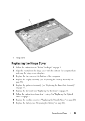
... 56). 5 Replace the palm-rest assembly (see "Replacing the Palm-Rest Assembly" on page 35). 6 Replace the keyboard (see "Replacing the Keyboard" on page 29). 7 Follow the instructions from step 4 to step 5 in "Replacing the Optical Drive" on page 21. 8 Replace the module cover (see "Replacing the Module Cover" on page 18). 9 Replace the battery (see "Replacing the Battery" on page...
... 56). 5 Replace the palm-rest assembly (see "Replacing the Palm-Rest Assembly" on page 35). 6 Replace the keyboard (see "Replacing the Keyboard" on page 29). 7 Follow the instructions from step 4 to step 5 in "Replacing the Optical Drive" on page 21. 8 Replace the module cover (see "Replacing the Module Cover" on page 18). 9 Replace the battery (see "Replacing the Battery" on page...

Service Manual
Page 75
VGA Connector Board 75 CAUTION: Before turning on page 16). Failure to do so may result in damage to the computer. 9 Replace the battery (see "Replacing the Battery" on the computer, replace all screws and ensure that no stray screws remain inside the computer.
VGA Connector Board 75 CAUTION: Before turning on page 16). Failure to do so may result in damage to the computer. 9 Replace the battery (see "Replacing the Battery" on the computer, replace all screws and ensure that no stray screws remain inside the computer.
Service Manual
Page 81
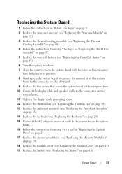
...Thermal Cooling Assembly" on page 90. 4 Follow the instructions from step 5 to step 7 in "Replacing the Hard-Drive Assembly" on page 97. 5 Replace the coin-cell battery (see "Replacing the Coin-Cell Battery" on page 88). 6 Turn the system board over. 7 Align the connectors on the system ... from step 4 to step 5 in "Replacing the Optical Drive" on page 21. 17 Replace the memory module(s) (see "Replacing the Memory Module(s)" on page 24). 18 Replace the module cover (see "Replacing the Module Cover" on page 18). 19 Replace the battery (see "Replacing the Battery" on page 16). System Board 81
...Thermal Cooling Assembly" on page 90. 4 Follow the instructions from step 5 to step 7 in "Replacing the Hard-Drive Assembly" on page 97. 5 Replace the coin-cell battery (see "Replacing the Coin-Cell Battery" on page 88). 6 Turn the system board over. 7 Align the connectors on the system ... from step 4 to step 5 in "Replacing the Optical Drive" on page 21. 17 Replace the memory module(s) (see "Replacing the Memory Module(s)" on page 24). 18 Replace the module cover (see "Replacing the Module Cover" on page 18). 19 Replace the battery (see "Replacing the Battery" on page 16). System Board 81

Service Manual
Page 82
... Tag in the BIOS" on the computer. 3 Press as soon as you have replaced the system board, enter the computer Service Tag in the BIOS of the replacement system board. 22 Enter the service tag (see the Dell logo to enter the system setup program. 4 Navigate to the computer. 21 Turn ...on the computer, replace all screws and ensure that the main battery is plugged in -1 media card reader. CAUTION: Before...
... Tag in the BIOS" on the computer. 3 Press as soon as you have replaced the system board, enter the computer Service Tag in the BIOS of the replacement system board. 22 Enter the service tag (see the Dell logo to enter the system setup program. 4 Navigate to the computer. 21 Turn ...on the computer, replace all screws and ensure that the main battery is plugged in -1 media card reader. CAUTION: Before...
Service Manual
Page 88
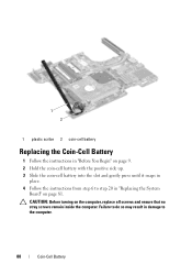
Failure to the computer. 88 Coin-Cell Battery 1 2 1 plastic scribe 2 coin-cell battery Replacing the Coin-Cell Battery 1 Follow the instructions in "Before You Begin" on page 9. 2 Hold the coin-cell battery with the positive side up. 3 Slide the coin-cell battery into the slot and gently press until it snaps in place. 4 Follow the instructions from step 6 to step 20 in damage to do so may result in "Replacing the System Board" on the computer, replace all screws and ensure that no stray screws remain inside the computer. CAUTION: Before turning on page 81.
Failure to the computer. 88 Coin-Cell Battery 1 2 1 plastic scribe 2 coin-cell battery Replacing the Coin-Cell Battery 1 Follow the instructions in "Before You Begin" on page 9. 2 Hold the coin-cell battery with the positive side up. 3 Slide the coin-cell battery into the slot and gently press until it snaps in place. 4 Follow the instructions from step 6 to step 20 in damage to do so may result in "Replacing the System Board" on the computer, replace all screws and ensure that no stray screws remain inside the computer. CAUTION: Before turning on page 81.


