Inspiron 14R N4110 Service Manual
Page 4
Replacing the Optical Drive 21 6 Memory Module(s 23 Removing the Memory Module(s 23 Replacing the Memory Module(s 24 7 Keyboard 27 Removing the Keyboard 27 Replacing the Keyboard 29 8 Palm-Rest Assembly 31 Removing the Palm-Rest Assembly 31 Replacing the Palm-Rest Assembly 34 9 Hot-Key Board 37 Removing the Hot-Key Board 37 Replacing the Hot-Key Board 38 10 Power Button Board 41 Removing the Power Button Board 41 Replacing the Power Button Board 42 4 Contents
Replacing the Optical Drive 21 6 Memory Module(s 23 Removing the Memory Module(s 23 Replacing the Memory Module(s 24 7 Keyboard 27 Removing the Keyboard 27 Replacing the Keyboard 29 8 Palm-Rest Assembly 31 Removing the Palm-Rest Assembly 31 Replacing the Palm-Rest Assembly 34 9 Hot-Key Board 37 Removing the Hot-Key Board 37 Replacing the Hot-Key Board 38 10 Power Button Board 41 Removing the Power Button Board 41 Replacing the Power Button Board 42 4 Contents
Inspiron 14R N4110 Service Manual
Page 6
Removing the Display Brackets 62 Replacing the Display Brackets 63 14 Camera Module 65 Removing the Camera Module 65 Replacing the Camera Module 66 15 Hinge Cover 69 Removing the Hinge Cover 69 Replacing the Hinge Cover 71 16 VGA Connector Board 73 Removing the VGA Connector Board 73 Replacing the VGA Connector Board 74 17 System Board 77 Removing the System Board 77 Replacing the System Board 81 Entering the Service Tag in the BIOS 82 18 Speakers 83 Removing the Speakers 83 Replacing the Speakers 84 6 Contents
Removing the Display Brackets 62 Replacing the Display Brackets 63 14 Camera Module 65 Removing the Camera Module 65 Replacing the Camera Module 66 15 Hinge Cover 69 Removing the Hinge Cover 69 Replacing the Hinge Cover 71 16 VGA Connector Board 73 Removing the VGA Connector Board 73 Replacing the VGA Connector Board 74 17 System Board 77 Removing the System Board 77 Replacing the System Board 81 Entering the Service Tag in the BIOS 82 18 Speakers 83 Removing the Speakers 83 Replacing the Speakers 84 6 Contents
Inspiron 14R N4110 Service Manual
Page 7
19 Coin-Cell Battery 87 Removing the Coin-Cell Battery 87 Replacing the Coin-Cell Battery 88 20 Thermal Cooling Assembly 89 Removing the Thermal Cooling Assembly 89 Replacing the Thermal Cooling Assembly 90 21 Processor Module 91 Removing the Processor Module 91 Replacing the Processor Module 92 22 Hard-Drive Assembly 95 Removing the Hard-Drive Assembly 95 Replacing the Hard-Drive Assembly 97 23 I/O Board 99 Removing the I/O Board 99 Replacing the I/O Board 100 24 AC-Adapter Connector 101 Removing the AC-Adapter Connector 101 Contents 7
19 Coin-Cell Battery 87 Removing the Coin-Cell Battery 87 Replacing the Coin-Cell Battery 88 20 Thermal Cooling Assembly 89 Removing the Thermal Cooling Assembly 89 Replacing the Thermal Cooling Assembly 90 21 Processor Module 91 Removing the Processor Module 91 Replacing the Processor Module 92 22 Hard-Drive Assembly 95 Removing the Hard-Drive Assembly 95 Replacing the Hard-Drive Assembly 97 23 I/O Board 99 Removing the I/O Board 99 Replacing the I/O Board 100 24 AC-Adapter Connector 101 Removing the AC-Adapter Connector 101 Contents 7
Inspiron 14R N4110 Service Manual
Page 10
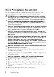
... pull connectors apart, keep them evenly aligned to avoid bending any installed cards from the 8-in on the locking tabs before you begin working inside the computer. 1 Ensure that both connectors are disconnecting this type of cable, press in -1 media card reader. 5 Disconnect your computer and all attached devices from potential damage and to help to prevent the computer cover from the...
... pull connectors apart, keep them evenly aligned to avoid bending any installed cards from the 8-in on the locking tabs before you begin working inside the computer. 1 Ensure that both connectors are disconnecting this type of cable, press in -1 media card reader. 5 Disconnect your computer and all attached devices from potential damage and to help to prevent the computer cover from the...
Inspiron 14R N4110 Service Manual
Page 18
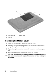
Failure to the computer. 18 Module Cover 1 2 3 1 captive screw 2 module cover 3 tabs (2) Replacing the Module Cover 1 Follow the instructions in "Before You Begin" on page 9. 2 Align the tabs on the module cover with the slots on page 16). CAUTION: Before turning on the computer, replace all screws and ensure that secures the module cover to the computer base. 4 Replace the battery (see "Replacing the Battery" on the computer base and gently snap the cover in damage to do so may result in place. 3 Tighten the captive screw that no stray screws remain inside the computer.
Failure to the computer. 18 Module Cover 1 2 3 1 captive screw 2 module cover 3 tabs (2) Replacing the Module Cover 1 Follow the instructions in "Before You Begin" on page 9. 2 Align the tabs on the module cover with the slots on page 16). CAUTION: Before turning on the computer, replace all screws and ensure that secures the module cover to the computer base. 4 Replace the battery (see "Replacing the Battery" on the computer base and gently snap the cover in damage to do so may result in place. 3 Tighten the captive screw that no stray screws remain inside the computer.
Inspiron 14R N4110 Service Manual
Page 23
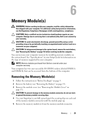
... by using a wrist grounding strap or by your Setup Guide for information on the type of memory supported by periodically touching an unpainted metal surface (such as a connector on each end of the computer. Damage due to servicing that is not authorized by Dell is not covered by installing memory modules on page 15) before working inside the computer. Your computer has two user-accessible SO...
... by using a wrist grounding strap or by your Setup Guide for information on the type of memory supported by periodically touching an unpainted metal surface (such as a connector on each end of the computer. Damage due to servicing that is not authorized by Dell is not covered by installing memory modules on page 15) before working inside the computer. Your computer has two user-accessible SO...
Inspiron 14R N4110 Service Manual
Page 24
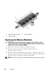
1 3 2 1 memory-module connector 2 securing clips (2) 3 memory module Replacing the Memory Module(s) CAUTION: If you need to install memory modules in two connectors, install a memory module in the memory-module connector. 3 Slide the memory module firmly into the slot at a 45-degree angle, and press the memory module down until it . NOTE: If the memory module is not installed properly, the computer may not boot. 24 Memory If you install a memory module in the connector labeled "DIMM B." 1 Follow the instructions in "Before...
1 3 2 1 memory-module connector 2 securing clips (2) 3 memory module Replacing the Memory Module(s) CAUTION: If you need to install memory modules in two connectors, install a memory module in the memory-module connector. 3 Slide the memory module firmly into the slot at a 45-degree angle, and press the memory module down until it . NOTE: If the memory module is not installed properly, the computer may not boot. 24 Memory If you install a memory module in the connector labeled "DIMM B." 1 Follow the instructions in "Before...
Inspiron 14R N4110 Service Manual
Page 35
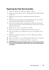
... Assembly 1 Follow the instructions in "Before You Begin" on page 9. 2 Replace the power button board (see "Replacing the Power Button Board" on page 42). 3 Replace the hot-key board (see "Replacing the Hot-Key Board" on page 38). 4 Align the tabs on the palm-rest assembly with the slots on the computer base and gently snap the palm-rest assembly in place. 5 Slide the power-button cable, touch-pad cable, and hot-key board cable into the connectors...
... Assembly 1 Follow the instructions in "Before You Begin" on page 9. 2 Replace the power button board (see "Replacing the Power Button Board" on page 42). 3 Replace the hot-key board (see "Replacing the Hot-Key Board" on page 38). 4 Align the tabs on the palm-rest assembly with the slots on the computer base and gently snap the palm-rest assembly in place. 5 Slide the power-button cable, touch-pad cable, and hot-key board cable into the connectors...
Inspiron 14R N4110 Service Manual
Page 48
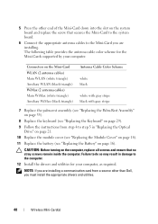
... so may result in "Replacing the Optical Drive" on page 21. 10 Replace the module cover (see "Replacing the Module Cover" on page 18). 11 Replace the battery (see "Replacing the Battery" on the computer, replace all screws and ensure that secures the Mini-Card to the system board. 6 Connect the appropriate antenna cables to the computer. 12 Install the drivers and utilities for the Mini-Cards supported by your computer, as...
... so may result in "Replacing the Optical Drive" on page 21. 10 Replace the module cover (see "Replacing the Module Cover" on page 18). 11 Replace the battery (see "Replacing the Battery" on the computer, replace all screws and ensure that secures the Mini-Card to the system board. 6 Connect the appropriate antenna cables to the computer. 12 Install the drivers and utilities for the Mini-Cards supported by your computer, as...
Inspiron 14R N4110 Service Manual
Page 82
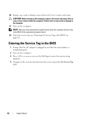
... removed from the 8-in the Set Service Tag field. 82 System Board CAUTION: Before turning on the computer, replace all screws and ensure that the main battery is installed properly. 2 Turn on the computer. 3 Press as soon as you have replaced the system board, enter the computer Service Tag in the BIOS of the replacement system board. 22 Enter the service tag (see the Dell logo to enter the system setup...
... removed from the 8-in the Set Service Tag field. 82 System Board CAUTION: Before turning on the computer, replace all screws and ensure that the main battery is installed properly. 2 Turn on the computer. 3 Press as soon as you have replaced the system board, enter the computer Service Tag in the BIOS of the replacement system board. 22 Enter the service tag (see the Dell logo to enter the system setup...
Inspiron 14R N4110 Service Manual
Page 97
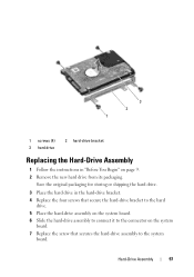
... hard-drive assembly to the system board. Save the original packaging for storing or shipping the hard drive. 3 Place the hard drive in "Before You Begin" on the system board. 7 Replace the screw that secure the hard-drive bracket to the hard drive. 5 Place the hard-drive assembly on the system board. 6 Slide the hard-drive assembly to connect it to the connector on page 9. 2 Remove the new hard drive from its packaging. Hard-Drive...
... hard-drive assembly to the system board. Save the original packaging for storing or shipping the hard drive. 3 Place the hard drive in "Before You Begin" on the system board. 7 Replace the screw that secure the hard-drive bracket to the hard drive. 5 Place the hard-drive assembly on the system board. 6 Slide the hard-drive assembly to connect it to the connector on page 9. 2 Remove the new hard drive from its packaging. Hard-Drive...
Inspiron 14R N4110 Setup Guide
Page 5
... Adapter 6 Connect the Network Cable (Optional 7 Press the Power Button 8 Set Up the Operating System 9 Create System Recovery Media (Recommended 10 Install the SIM Card (Optional 12 Enable or Disable Wireless (Optional 14 Set Up Wireless Display (Optional 16 Connect to the Internet (Optional 18 Using Your Inspiron Laptop 22 Right View Features 22 Left View Features 24 Back View Features 28 Front View Features 30 Status Lights and Indicators 32 Disabling Battery Charging 33 Computer Base and Keyboard Features 34 Touch Pad Gestures 38 Multimedia Control Keys...
... Adapter 6 Connect the Network Cable (Optional 7 Press the Power Button 8 Set Up the Operating System 9 Create System Recovery Media (Recommended 10 Install the SIM Card (Optional 12 Enable or Disable Wireless (Optional 14 Set Up Wireless Display (Optional 16 Connect to the Internet (Optional 18 Using Your Inspiron Laptop 22 Right View Features 22 Left View Features 24 Back View Features 28 Front View Features 30 Status Lights and Indicators 32 Disabling Battery Charging 33 Computer Base and Keyboard Features 34 Touch Pad Gestures 38 Multimedia Control Keys...
Inspiron 14R N4110 Setup Guide
Page 6
... Problems 56 Beep Codes 56 Network Problems 57 Power Problems 57 Memory Problems 59 Lockups and Software Problems 59 Using Support Tools 62 Dell Support Center 62 My Dell Downloads 63 Hardware Troubleshooter 64 Dell Diagnostics 64 Restoring Your Operating System 66 System Restore 67 Dell DataSafe Local Backup 68 System Recovery Media 71 Dell Factory Image Restore 72 Getting Help 74 Technical Support and Customer Service 75 DellConnect 75 Online Services 76 Automated Order-Status Service 77 Product Information 77 Returning Items for Repair...
... Problems 56 Beep Codes 56 Network Problems 57 Power Problems 57 Memory Problems 59 Lockups and Software Problems 59 Using Support Tools 62 Dell Support Center 62 My Dell Downloads 63 Hardware Troubleshooter 64 Dell Diagnostics 64 Restoring Your Operating System 66 System Restore 67 Dell DataSafe Local Backup 68 System Recovery Media 71 Dell Factory Image Restore 72 Getting Help 74 Technical Support and Customer Service 75 DellConnect 75 Online Services 76 Automated Order-Status Service 77 Product Information 77 Returning Items for Repair...
Inspiron 14R N4110 Setup Guide
Page 12
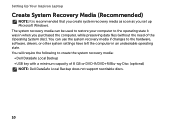
... the hardware, software, drivers, or other system settings have left the computer in when you set up Microsoft Windows. You can be used to restore your computer to the operating state it was in an undesirable operating state. The system recovery media can use the system recovery media if changes to create the system recovery media: • Dell DataSafe Local Backup • USB key with a minimum capacity of the Operating System disc). Setting Up Your Inspiron Laptop Create System Recovery Media...
... the hardware, software, drivers, or other system settings have left the computer in when you set up Microsoft Windows. You can be used to restore your computer to the operating state it was in an undesirable operating state. The system recovery media can use the system recovery media if changes to create the system recovery media: • Dell DataSafe Local Backup • USB key with a minimum capacity of the Operating System disc). Setting Up Your Inspiron Laptop Create System Recovery Media...
Inspiron 14R N4110 Setup Guide
Page 19
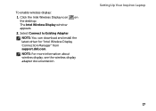
The Intel Wireless Display window appears. 2. Setting Up Your Inspiron Laptop 17 NOTE: You can download and install the latest driver for "Intel Wireless Display Connection Manager" from support.dell.com. NOTE: For more information about wireless display, see the wireless display adapter documentation. Select Connect to Existing Adapter. To enable wireless display: 1. Click the Intel Wireless Display icon on the desktop.
The Intel Wireless Display window appears. 2. Setting Up Your Inspiron Laptop 17 NOTE: You can download and install the latest driver for "Intel Wireless Display Connection Manager" from support.dell.com. NOTE: For more information about wireless display, see the wireless display adapter documentation. Select Connect to Existing Adapter. To enable wireless display: 1. Click the Intel Wireless Display icon on the desktop.
Inspiron 14R N4110 Setup Guide
Page 58
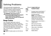
... are errors or problems. This series of beeps, called a beep code, identifies a problem. Chipset error Four RAM read/write failure Five Real Time Clock failure Six Video card or chip failure Seven Processor failure Eight Display failure 56 See the Service Manual at support.dell.com. If you installed or replaced the memory module, ensure that the memory module is seated properly. INSPIRON Solving Problems This section provides troubleshooting information for your problem using the...
... are errors or problems. This series of beeps, called a beep code, identifies a problem. Chipset error Four RAM read/write failure Five Real Time Clock failure Six Video card or chip failure Seven Processor failure Eight Display failure 56 See the Service Manual at support.dell.com. If you installed or replaced the memory module, ensure that the memory module is seated properly. INSPIRON Solving Problems This section provides troubleshooting information for your problem using the...
Inspiron 14R N4110 Setup Guide
Page 60
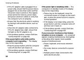
... in standby mode or the display may not be responding. • Press a key on the keyboard, move the connected mouse or a finger on the touch pad, or press the power button to the same electrical outlet. Also bypass power protection devices, power strips, and power extension cables to verify that the computer turns on page 82). 58 If the power light is not responding - If the power light is solid...
... in standby mode or the display may not be responding. • Press a key on the keyboard, move the connected mouse or a finger on the touch pad, or press the power button to the same electrical outlet. Also bypass power protection devices, power strips, and power extension cables to verify that the computer turns on page 82). 58 If the power light is not responding - If the power light is solid...
Inspiron 14R N4110 Setup Guide
Page 61
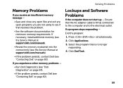
... necessary, install additional memory (see the Service Manual at support.dell.com/manuals). • Reseat the memory module(s) into the connector(s) (see the Service Manual at support.dell.com/manuals). • If the problem persists, contact Dell (see if that is firmly connected to the computer and to see "Contacting Dell" on page 82). Lockups and Software Problems If the computer does not start up - If you are not using to the...
... necessary, install additional memory (see the Service Manual at support.dell.com/manuals). • Reseat the memory module(s) into the connector(s) (see the Service Manual at support.dell.com/manuals). • If the problem persists, contact Dell (see if that is firmly connected to the computer and to see "Contacting Dell" on page 82). Lockups and Software Problems If the computer does not start up - If you are not using to the...
Inspiron 14R N4110 Setup Guide
Page 88
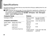
... Intel Pentium Dual Core Memory module connector Memory module capacities Minimum memory Maximum memory Possible memory configurations two user-accessible SODIMM connectors 1 GB, 2 GB, and 4 GB 2 GB 8 GB 2 GB, 3 GB, 4 GB, 6 GB, and 8 GB 86 To launch the Dell Support Center, click Start → All Programs→ Dell→ Dell Support Center→ Launch Dell Support Center. NOTE: Offerings may need when setting up, updating drivers for, and upgrading your computer, see the...
... Intel Pentium Dual Core Memory module connector Memory module capacities Minimum memory Maximum memory Possible memory configurations two user-accessible SODIMM connectors 1 GB, 2 GB, and 4 GB 2 GB 8 GB 2 GB, 3 GB, 4 GB, 6 GB, and 8 GB 86 To launch the Dell Support Center, click Start → All Programs→ Dell→ Dell Support Center→ Launch Dell Support Center. NOTE: Offerings may need when setting up, updating drivers for, and upgrading your computer, see the...
Inspiron 14R N4110 Setup Guide
Page 99
problems, solving 56 products information and purchasing 77 R resources, finding more 84 restoring factory image 72 S Service Tag locating 80 setup, before you begin 5 shipping products for return or repair 78 SIM card 12 software features 52 software problems 59 solving problems 56 specifications 86 support e-mail addresses 76 support sites worldwide 76 System Recovery Media 71 system reinstall options 66 System Restore 67 T Touch Pad Gestures 38 U Using the Emergency Eject Hole 42 V ventilation, ensuring 5 W warranty returns 78 Windows Index 97
problems, solving 56 products information and purchasing 77 R resources, finding more 84 restoring factory image 72 S Service Tag locating 80 setup, before you begin 5 shipping products for return or repair 78 SIM card 12 software features 52 software problems 59 solving problems 56 specifications 86 support e-mail addresses 76 support sites worldwide 76 System Recovery Media 71 system reinstall options 66 System Restore 67 T Touch Pad Gestures 38 U Using the Emergency Eject Hole 42 V ventilation, ensuring 5 W warranty returns 78 Windows Index 97


