Owner's Manual
Page 3
Contents 1 Before You Begin 9 Recommended Tools 9 Turning Off Your Computer 10 Before Working Inside Your Computer 10 2 Battery 13 Removing the Battery 13 Replacing the Battery 14 3 Keyboard 15 Removing the Keyboard 15 Replacing the Keyboard 17 4 Memory Module(s 19 Removing the Memory Module(s 19 Replacing the Memory Module(s 20 Contents 3
Contents 1 Before You Begin 9 Recommended Tools 9 Turning Off Your Computer 10 Before Working Inside Your Computer 10 2 Battery 13 Removing the Battery 13 Replacing the Battery 14 3 Keyboard 15 Removing the Keyboard 15 Replacing the Keyboard 17 4 Memory Module(s 19 Removing the Memory Module(s 19 Replacing the Memory Module(s 20 Contents 3

Owner's Manual
Page 5
10 Audio Board 41 Removing the Audio Board 41 Replacing the Audio Board 42 11 Coin-Cell Battery 43 Removing the Coin-Cell Battery 43 Replacing the Coin-Cell Battery 45 12 USB Board 47 Removing the USB Board 47 Replacing the USB Board 48 13 Thermal Cooling Assembly 49 Removing the Thermal Cooling Assembly 49 Replacing the Thermal Cooling Assembly 50 14 Processor Module (For Inspiron 14-N4050 Only 51 Removing the Processor Module 51 Replacing the Processor Module 52 Contents 5
10 Audio Board 41 Removing the Audio Board 41 Replacing the Audio Board 42 11 Coin-Cell Battery 43 Removing the Coin-Cell Battery 43 Replacing the Coin-Cell Battery 45 12 USB Board 47 Removing the USB Board 47 Replacing the USB Board 48 13 Thermal Cooling Assembly 49 Removing the Thermal Cooling Assembly 49 Replacing the Thermal Cooling Assembly 50 14 Processor Module (For Inspiron 14-N4050 Only 51 Removing the Processor Module 51 Replacing the Processor Module 52 Contents 5
Owner's Manual
Page 6
15 Hinge Cover 55 Removing the Hinge Cover 55 Replacing the Hinge Cover 57 16 Display 59 Display Assembly 59 Removing the Display Assembly 59 Replacing the Display Assembly 61 Display Bezel 62 Removing the Display Bezel 62 Replacing the Display Bezel 63 Removing the Display Panel 63 Replacing the Display Panel 66 17 Camera Module 69 Removing the Camera Module 69 Replacing the Camera Module 70 18 System Board 73 Removing the System Board 73 Replacing the System Board 75 Entering the Service Tag in the BIOS 76 19 Flashing the BIOS 77 6 Contents
15 Hinge Cover 55 Removing the Hinge Cover 55 Replacing the Hinge Cover 57 16 Display 59 Display Assembly 59 Removing the Display Assembly 59 Replacing the Display Assembly 61 Display Bezel 62 Removing the Display Bezel 62 Replacing the Display Bezel 63 Removing the Display Panel 63 Replacing the Display Panel 66 17 Camera Module 69 Removing the Camera Module 69 Replacing the Camera Module 70 18 System Board 73 Removing the System Board 73 Replacing the System Board 75 Entering the Service Tag in the BIOS 76 19 Flashing the BIOS 77 6 Contents
Owner's Manual
Page 11
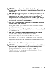
..., open the display, and press the power button to the system board, remove the main battery, see "Turning Off Your Computer" on page 10, and all attached devices from the 3-in on the locking tabs before you begin working inside the computer. 1 Ensure that both connectors are disconnecting this type of cable, press in -1 media card reader. 5 Disconnect your computer. CAUTION: When you pull connectors apart, keep...
..., open the display, and press the power button to the system board, remove the main battery, see "Turning Off Your Computer" on page 10, and all attached devices from the 3-in on the locking tabs before you begin working inside the computer. 1 Ensure that both connectors are disconnecting this type of cable, press in -1 media card reader. 5 Disconnect your computer. CAUTION: When you pull connectors apart, keep...

Owner's Manual
Page 15
..., and time-consuming to the system board, remove the main battery, see the Regulatory Compliance Homepage at www.dell.com/regulatory_compliance. CAUTION: To avoid electrostatic discharge, ground yourself by using a wrist grounding strap or by your computer). Removing the Keyboard 1 Follow the instructions in "Before You Begin" on page 13. 3 Keyboard WARNING: Before working inside your computer, read the safety...
..., and time-consuming to the system board, remove the main battery, see the Regulatory Compliance Homepage at www.dell.com/regulatory_compliance. CAUTION: To avoid electrostatic discharge, ground yourself by using a wrist grounding strap or by your computer). Removing the Keyboard 1 Follow the instructions in "Before You Begin" on page 13. 3 Keyboard WARNING: Before working inside your computer, read the safety...

Owner's Manual
Page 19
... to the memory module connector, do not use tools to the system board, remove the main battery, see the Regulatory Compliance Homepage at support.dell.com/manuals. Your computer has two user-accessible SODIMM sockets, labeled DIMM A and DIMM B, that can increase your computer warranty. Removing the Memory Module(s) 1 Follow the instructions in "Before You Begin" on page 15. See "Removing the Keyboard" on page 9. 2 Remove the battery. CAUTION...
... to the memory module connector, do not use tools to the system board, remove the main battery, see the Regulatory Compliance Homepage at support.dell.com/manuals. Your computer has two user-accessible SODIMM sockets, labeled DIMM A and DIMM B, that can increase your computer warranty. Removing the Memory Module(s) 1 Follow the instructions in "Before You Begin" on page 15. See "Removing the Keyboard" on page 9. 2 Remove the battery. CAUTION...

Owner's Manual
Page 20
... the memory module is not installed properly, the computer may not boot. 20 Memory 1 3 2 1 memory-module connector 2 securing clips (2) 3 memory module Replacing the Memory Module(s) CAUTION: If you need to install memory modules in two connectors, install a memory module in the memory-module connector. 3 Slide the memory module firmly into place. If you install a memory module in the connector labeled "DIMM B." 1 Follow the instructions in "Before You Begin" on page 9. 2 Align the notch in the memory module with the...
... the memory module is not installed properly, the computer may not boot. 20 Memory 1 3 2 1 memory-module connector 2 securing clips (2) 3 memory module Replacing the Memory Module(s) CAUTION: If you need to install memory modules in two connectors, install a memory module in the memory-module connector. 3 Slide the memory module firmly into place. If you install a memory module in the connector labeled "DIMM B." 1 Follow the instructions in "Before You Begin" on page 9. 2 Align the notch in the memory module with the...

Owner's Manual
Page 33
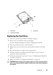
... not covered by periodically touching an unpainted metal surface (such as a connector on page 10, before working inside the computer. CAUTION: Hard drives are installing a hard drive from sources other than Dell. Removing the Hard Drive 1 Follow the instructions in Sleep state. 8 Hard Drive WARNING: Before working inside your computer, read the safety information that is not authorized by Dell is hot, do not touch the metal housing of the hard drive...
... not covered by periodically touching an unpainted metal surface (such as a connector on page 10, before working inside the computer. CAUTION: Hard drives are installing a hard drive from sources other than Dell. Removing the Hard Drive 1 Follow the instructions in Sleep state. 8 Hard Drive WARNING: Before working inside your computer, read the safety information that is not authorized by Dell is hot, do not touch the metal housing of the hard drive...
Owner's Manual
Page 35
... connect it to the connector on the system board. 7 Follow the instructions from step 3 to step 7 in "Replacing the Palm-Rest Assembly" on page 9. 2 Remove the new hard drive from its packaging. 1 3 2 1 hard drive 3 hard-drive bracket 2 screws (2) Replacing the Hard Drive 1 Follow the instructions in damage to the computer. Failure to do so may result in "Before You Begin" on page 28. 8 Replace the battery. Hard Drive 35 See "Replacing...
... connect it to the connector on the system board. 7 Follow the instructions from step 3 to step 7 in "Replacing the Palm-Rest Assembly" on page 9. 2 Remove the new hard drive from its packaging. 1 3 2 1 hard drive 3 hard-drive bracket 2 screws (2) Replacing the Hard Drive 1 Follow the instructions in damage to the computer. Failure to do so may result in "Before You Begin" on page 28. 8 Replace the battery. Hard Drive 35 See "Replacing...

Owner's Manual
Page 39
.... 8 Install the drivers and utilities for the Mini-Cards supported by your computer, as required. Wireless Mini-Card 39 If you use excessive force, you must install the appropriate drivers and utilities. NOTE: If you feel resistance, check the connectors on the card and on the Mini-Card WLAN (2 antenna cables) Main WLAN (white triangle) Auxiliary WLAN (black triangle) Antenna Cable Color Scheme white black 6 Follow the instructions...
.... 8 Install the drivers and utilities for the Mini-Cards supported by your computer, as required. Wireless Mini-Card 39 If you use excessive force, you must install the appropriate drivers and utilities. NOTE: If you feel resistance, check the connectors on the card and on the Mini-Card WLAN (2 antenna cables) Main WLAN (white triangle) Auxiliary WLAN (black triangle) Antenna Cable Color Scheme white black 6 Follow the instructions...

Owner's Manual
Page 45
.... For Inspiron 14-N4050: a Slide the coin-cell battery into the connector on page 9. Press down on the connector latch to secure the audio-board cable to the connector on the system board. 2 Follow the instructions from step 3 to step 7 in damage to the computer. Coin-Cell Battery 45 b Connect the coin-cell battery cable to do so may result in "Replacing the...
.... For Inspiron 14-N4050: a Slide the coin-cell battery into the connector on page 9. Press down on the connector latch to secure the audio-board cable to the connector on the system board. 2 Follow the instructions from step 3 to step 7 in damage to the computer. Coin-Cell Battery 45 b Connect the coin-cell battery cable to do so may result in "Replacing the...
Owner's Manual
Page 48
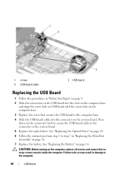
... computer base and align the screw hole on USB board with the screw hole on the computer base. 3 Replace the screw that no stray screws remain inside the computer. CAUTION: Before turning on the system board. 5 Replace the optical drive. Press down on the connector latch to secure the USB-board cable to the computer. 48 USB Board See "Replacing the Battery" on page 14.
... computer base and align the screw hole on USB board with the screw hole on the computer base. 3 Replace the screw that no stray screws remain inside the computer. CAUTION: Before turning on the system board. 5 Replace the optical drive. Press down on the connector latch to secure the USB-board cable to the computer. 48 USB Board See "Replacing the Battery" on page 14.

Owner's Manual
Page 51
... Assembly" on page 9. 2 Remove the battery. Processor Module (For Inspiron 14-N4050 Only) 51 CAUTION: Only a certified service technician should perform repairs on the processor thermal cooling assembly. Damage due to the system board, remove the main battery, see the Regulatory Compliance Homepage at www.dell.com/regulatory_compliance. CAUTION: Handle components and cards by their edges, and avoid touching pins and contacts. See...
... Assembly" on page 9. 2 Remove the battery. Processor Module (For Inspiron 14-N4050 Only) 51 CAUTION: Only a certified service technician should perform repairs on the processor thermal cooling assembly. Damage due to the system board, remove the main battery, see the Regulatory Compliance Homepage at www.dell.com/regulatory_compliance. CAUTION: Handle components and cards by their edges, and avoid touching pins and contacts. See...
Owner's Manual
Page 52
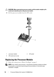
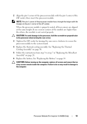
NOTE: If you install a new processor, a new thermal assembly including an affixed thermal pad or a new thermal pad along with documentation to bend the pins on the processor module. 6 Lift the processor module from the ZIF socket. 3 1 2 1 processor module 3 ZIF-socket cam screw 2 ZIF socket Replacing the Processor Module 1 Follow the instructions in "Before You Begin" on page 9. CAUTION: When removing the processor module, pull the module straight up. Be careful not to illustrate proper installation is shipped. 52 Processor Module (For Inspiron 14-N4050 Only)
NOTE: If you install a new processor, a new thermal assembly including an affixed thermal pad or a new thermal pad along with documentation to bend the pins on the processor module. 6 Lift the processor module from the ZIF socket. 3 1 2 1 processor module 3 ZIF-socket cam screw 2 ZIF socket Replacing the Processor Module 1 Follow the instructions in "Before You Begin" on page 9. CAUTION: When removing the processor module, pull the module straight up. Be careful not to illustrate proper installation is shipped. 52 Processor Module (For Inspiron 14-N4050 Only)
Owner's Manual
Page 53
If one or more corners of the module are aligned at the same height. See "Replacing the Battery" on page 14. Processor Module (For Inspiron 14-N4050 Only) 53 CAUTION: To avoid damage to the processor, hold the screwdriver perpendicular to the processor when turning the cam screw. 3 Tighten the ZIF socket by turning the cam screw clockwise to secure...
If one or more corners of the module are aligned at the same height. See "Replacing the Battery" on page 14. Processor Module (For Inspiron 14-N4050 Only) 53 CAUTION: To avoid damage to the processor, hold the screwdriver perpendicular to the processor when turning the cam screw. 3 Tighten the ZIF socket by turning the cam screw clockwise to secure...
Owner's Manual
Page 57
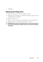
1 hinge cover Replacing the Hinge Cover 1 Follow the instructions in damage to the computer base. 5 Replace the battery. Hinge Cover 57 CAUTION: Before turning on the computer base and snap the hinge cover into place. 3 Turn the computer over. 4 Replace the two screws that no stray screws remain inside the computer. Failure to do so may result in "Before You Begin" on page 9. 2 Align the tabs on the hinge cover with the slots on the computer, replace all screws and ensure that secure the hinge cover to the computer. See "Replacing the Battery" on page 14.
1 hinge cover Replacing the Hinge Cover 1 Follow the instructions in damage to the computer base. 5 Replace the battery. Hinge Cover 57 CAUTION: Before turning on the computer base and snap the hinge cover into place. 3 Turn the computer over. 4 Replace the two screws that no stray screws remain inside the computer. Failure to do so may result in "Before You Begin" on page 9. 2 Align the tabs on the hinge cover with the slots on the computer, replace all screws and ensure that secure the hinge cover to the computer. See "Replacing the Battery" on page 14.
Owner's Manual
Page 63
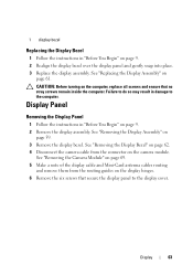
..." on the camera module. See "Replacing the Display Assembly" on page 9. 2 Realign the display bezel over the display panel and gently snap into place. 3 Replace the display assembly. Failure to the display cover. See "Removing the Camera Module" on page 69. 5 Make a note of the display cable and Mini-Card antenna cables routing and remove them from the connector on page 9. 2 Remove the display assembly. 1 display bezel Replacing the Display Bezel 1 Follow the instructions in "Before...
..." on the camera module. See "Replacing the Display Assembly" on page 9. 2 Realign the display bezel over the display panel and gently snap into place. 3 Replace the display assembly. Failure to the display cover. See "Removing the Camera Module" on page 69. 5 Make a note of the display cable and Mini-Card antenna cables routing and remove them from the connector on page 9. 2 Remove the display assembly. 1 display bezel Replacing the Display Bezel 1 Follow the instructions in "Before...
Owner's Manual
Page 69
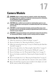
... Battery" on page 25. 4 Remove the optical drive. See "Removing the USB Board" on page 55. 7 Remove the display assembly. CAUTION: Only a certified service technician should perform repairs on page 59. 8 Remove the display bezel. See "Removing the Display Bezel" on page 62. 9 Disconnect the camera cable from step 3 to the system board, remove the main battery, see the Regulatory Compliance Homepage at www.dell.com/regulatory_compliance. 17 Camera Module WARNING: Before working...
... Battery" on page 25. 4 Remove the optical drive. See "Removing the USB Board" on page 55. 7 Remove the display assembly. CAUTION: Only a certified service technician should perform repairs on page 59. 8 Remove the display bezel. See "Removing the Display Bezel" on page 62. 9 Disconnect the camera cable from step 3 to the system board, remove the main battery, see the Regulatory Compliance Homepage at www.dell.com/regulatory_compliance. 17 Camera Module WARNING: Before working...
Owner's Manual
Page 73
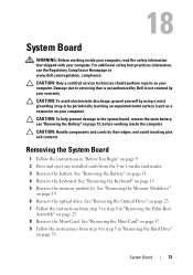
... damage to step 8 in -1 media card reader. 3 Remove the battery. See "Removing the Battery" on page 19. 6 Remove the optical drive. See "Removing the Memory Module(s)" on page 13. 4 Remove the keyboard. System Board 73 See "Removing the Optical Drive" on page 23. 7 Follow the instructions from step 3 to the system board, remove the main battery, see the Regulatory Compliance Homepage at www.dell.com/regulatory_compliance. See "Removing the Keyboard" on page 37. 9 Follow...
... damage to step 8 in -1 media card reader. 3 Remove the battery. See "Removing the Battery" on page 19. 6 Remove the optical drive. See "Removing the Memory Module(s)" on page 13. 4 Remove the keyboard. System Board 73 See "Removing the Optical Drive" on page 23. 7 Follow the instructions from step 3 to the system board, remove the main battery, see the Regulatory Compliance Homepage at www.dell.com/regulatory_compliance. See "Removing the Keyboard" on page 37. 9 Follow...
Owner's Manual
Page 76
... BIOS 1 Ensure that the AC adapter is installed properly. 2 Turn on the computer. 3 Press during POST to enter the system setup program. 4 Navigate to the computer. 15 Turn on page 76. See "Replacing the Optical Drive" on page 20. 12 Replace the keyboard. 9 Follow the instructions from step 3 to do so may result in -1 media card reader. See "Replacing the Memory Module(s)" on page 24. 11 Replace the memory module(s). See "Replacing...
... BIOS 1 Ensure that the AC adapter is installed properly. 2 Turn on the computer. 3 Press during POST to enter the system setup program. 4 Navigate to the computer. 15 Turn on page 76. See "Replacing the Optical Drive" on page 20. 12 Replace the keyboard. 9 Follow the instructions from step 3 to do so may result in -1 media card reader. See "Replacing the Memory Module(s)" on page 24. 11 Replace the memory module(s). See "Replacing...


