

Owners Manual
Page 1
P18F002; Dell Inspiron M5040/15-N5040/ 15-N5050/3520 Owner's Manual Regulatory model: P18F Regulatory type: P18F001; P18F003
P18F002; Dell Inspiron M5040/15-N5040/ 15-N5050/3520 Owner's Manual Regulatory model: P18F Regulatory type: P18F001; P18F003
Owners Manual
Page 2
...by Bluetooth SIG, Inc.; A01 Notes, Cautions, and Warnings NOTE: A NOTE indicates important information that helps you make better use of Dell Inc.; CAUTION: A CAUTION indicates potential damage to hardware or loss of data if instructions are either trademarks or registered trademarks of Microsoft... Corporation in this text: Dell™, the DELL logo, and Inspiron™ are trademarks of your computer. Trademarks used in the United States and/or other countries. P18F003 2012 - ...
...by Bluetooth SIG, Inc.; A01 Notes, Cautions, and Warnings NOTE: A NOTE indicates important information that helps you make better use of Dell Inc.; CAUTION: A CAUTION indicates potential damage to hardware or loss of data if instructions are either trademarks or registered trademarks of Microsoft... Corporation in this text: Dell™, the DELL logo, and Inspiron™ are trademarks of your computer. Trademarks used in the United States and/or other countries. P18F003 2012 - ...
Owners Manual
Page 3
Contents 1 Before You Begin 9 Recommended Tools 9 Turning Off Your Computer 10 Before Working Inside Your Computer 10 2 Battery 13 Removing the Battery 13 Replacing the Battery 14 3 Keyboard 15 Removing the Keyboard 15 Replacing the Keyboard 17 4 Memory Module(s 19 Removing the Memory Module(s 19 Replacing the Memory Module(s 20 Contents 3
Contents 1 Before You Begin 9 Recommended Tools 9 Turning Off Your Computer 10 Before Working Inside Your Computer 10 2 Battery 13 Removing the Battery 13 Replacing the Battery 14 3 Keyboard 15 Removing the Keyboard 15 Replacing the Keyboard 17 4 Memory Module(s 19 Removing the Memory Module(s 19 Replacing the Memory Module(s 20 Contents 3

Owners Manual
Page 4
5 Optical Drive 23 Removing the Optical Drive 23 Replacing the Optical Drive 24 6 Wireless Mini-Card 25 Removing the Mini-Card 25 Replacing the Mini-Card 27 7 Palm-Rest Assembly 29 Removing the Palm-Rest Assembly 29 Replacing the Palm-Rest Assembly 32 8 Power Button Board 35 Removing the Power Button Board 35 Replacing the Power Button Board 36 9 Hard Drive 37 Removing the Hard Drive 37 Replacing the Hard Drive 39 4 Contents
5 Optical Drive 23 Removing the Optical Drive 23 Replacing the Optical Drive 24 6 Wireless Mini-Card 25 Removing the Mini-Card 25 Replacing the Mini-Card 27 7 Palm-Rest Assembly 29 Removing the Palm-Rest Assembly 29 Replacing the Palm-Rest Assembly 32 8 Power Button Board 35 Removing the Power Button Board 35 Replacing the Power Button Board 36 9 Hard Drive 37 Removing the Hard Drive 37 Replacing the Hard Drive 39 4 Contents
Owners Manual
Page 5
10 Coin-Cell Battery 41 Removing the Coin-Cell Battery 41 Replacing the Coin-Cell Battery 42 11 USB Board 43 Removing the USB Board 43 Replacing the USB Board 44 12 Thermal Cooling Assembly 45 Removing the Thermal Cooling Assembly 45 Replacing the Thermal Cooling Assembly 46 13 Processor Module (For Inspiron 15-N5050/15-N5040 Only 47 Removing the Processor Module 47 Replacing the Processor Module 48 14 Hinge Cover 51 Removing the Hinge Cover 51 Replacing the Hinge Cover 53 Contents 5
10 Coin-Cell Battery 41 Removing the Coin-Cell Battery 41 Replacing the Coin-Cell Battery 42 11 USB Board 43 Removing the USB Board 43 Replacing the USB Board 44 12 Thermal Cooling Assembly 45 Removing the Thermal Cooling Assembly 45 Replacing the Thermal Cooling Assembly 46 13 Processor Module (For Inspiron 15-N5050/15-N5040 Only 47 Removing the Processor Module 47 Replacing the Processor Module 48 14 Hinge Cover 51 Removing the Hinge Cover 51 Replacing the Hinge Cover 53 Contents 5
Owners Manual
Page 6
15 Display 55 Display Assembly 55 Removing the Display Assembly 55 Replacing the Display Assembly 58 Display Bezel 59 Removing the Display Bezel 59 Replacing the Display Bezel 60 Removing the Display Panel 60 Replacing the Display Panel 63 16 Camera Module 65 Removing the Camera Module 65 Replacing the Camera Module 66 17 System Board 67 Removing the System Board 67 Replacing the System Board 69 Entering the Service Tag in the BIOS 70 18 Flashing the BIOS 71 6 Contents
15 Display 55 Display Assembly 55 Removing the Display Assembly 55 Replacing the Display Assembly 58 Display Bezel 59 Removing the Display Bezel 59 Replacing the Display Bezel 60 Removing the Display Panel 60 Replacing the Display Panel 63 16 Camera Module 65 Removing the Camera Module 65 Replacing the Camera Module 66 17 System Board 67 Removing the System Board 67 Replacing the System Board 69 Entering the Service Tag in the BIOS 70 18 Flashing the BIOS 71 6 Contents

Owners Manual
Page 9
... document may require the following tools: • Small flat-blade screwdriver • Phillips screwdriver • Plastic scribe • BIOS executable update program available at support.dell.com Before You Begin 9 1 Before You Begin This manual provides procedures for removing and installing components in your computer. • A component can be replaced or...
... document may require the following tools: • Small flat-blade screwdriver • Phillips screwdriver • Plastic scribe • BIOS executable update program available at support.dell.com Before You Begin 9 1 Before You Begin This manual provides procedures for removing and installing components in your computer. • A component can be replaced or...
Owners Manual
Page 10
... information that the computer is completed. CAUTION: To avoid electrostatic discharge, ground yourself by using a different operating system, see the Regulatory Compliance Homepage at www.dell.com/regulatory_compliance. Hold a component such as a processor by its edges, not by periodically touching an unpainted metal surface (such as a connector on a card. Before Working...
... information that the computer is completed. CAUTION: To avoid electrostatic discharge, ground yourself by using a different operating system, see the Regulatory Compliance Homepage at www.dell.com/regulatory_compliance. Hold a component such as a processor by its edges, not by periodically touching an unpainted metal surface (such as a connector on a card. Before Working...
Owners Manual
Page 11
... the battery. CAUTION: To avoid damaging the computer, perform the following steps before you connect a cable, ensure that the work surface is not covered by Dell is flat and clean to ground the system board. As you begin working inside the computer. 1 Ensure that both connectors are disconnecting this type of...
... the battery. CAUTION: To avoid damaging the computer, perform the following steps before you connect a cable, ensure that the work surface is not covered by Dell is flat and clean to ground the system board. As you begin working inside the computer. 1 Ensure that both connectors are disconnecting this type of...

Owners Manual
Page 12
12 Before You Begin
12 Before You Begin

Owners Manual
Page 13
...by your computer. Battery 13 Damage due to servicing that shipped with your warranty. Do not use only the battery designed for other Dell computers. CAUTION: Only a certified service technician should perform repairs on your computer. Removing the Battery 1 Follow the instructions in the unlock...out of the battery bay. 2 Battery WARNING: Before working inside your computer, read the safety information that is not authorized by Dell is not covered by periodically touching an unpainted metal surface (such as a connector on your computer). CAUTION: To avoid damage to...
...by your computer. Battery 13 Damage due to servicing that shipped with your warranty. Do not use only the battery designed for other Dell computers. CAUTION: Only a certified service technician should perform repairs on your computer. Removing the Battery 1 Follow the instructions in the unlock...out of the battery bay. 2 Battery WARNING: Before working inside your computer, read the safety information that is not authorized by Dell is not covered by periodically touching an unpainted metal surface (such as a connector on your computer). CAUTION: To avoid damage to...

Owners Manual
Page 14
3 2 1 1 battery release latch 3 battery lock latch 2 battery Replacing the Battery 1 Follow the instructions in "Before You Begin" on page 9. 2 Slide the battery into the battery bay until it clicks into place. 3 Slide the battery lock latch to the lock position. 14 Battery
3 2 1 1 battery release latch 3 battery lock latch 2 battery Replacing the Battery 1 Follow the instructions in "Before You Begin" on page 9. 2 Slide the battery into the battery bay until it clicks into place. 3 Slide the battery lock latch to the lock position. 14 Battery
Owners Manual
Page 15
...safety best practices information, see "Removing the Battery" on your computer. Keyboard 15 Be careful when removing and handling the keyboard. 3 Turn the computer over and... the system board, remove the main battery, see the Regulatory Compliance Homepage at www.dell.com/regulatory_compliance. See "Removing the Battery" on page 9. 2 Remove the battery. Damage due to servicing that... is not authorized by Dell is not covered by periodically touching an unpainted metal surface (such as possible. 4 Using a plastic ...
...safety best practices information, see "Removing the Battery" on your computer. Keyboard 15 Be careful when removing and handling the keyboard. 3 Turn the computer over and... the system board, remove the main battery, see the Regulatory Compliance Homepage at www.dell.com/regulatory_compliance. See "Removing the Battery" on page 9. 2 Remove the battery. Damage due to servicing that... is not authorized by Dell is not covered by periodically touching an unpainted metal surface (such as possible. 4 Using a plastic ...

Owners Manual
Page 16
1 2 3 1 plastic scribe 3 keyboard 2 tabs (4) CAUTION: The keycaps on the keyboard are fragile, easily dislodged, and time-consuming to the connector on the palm rest assembly. 6 Lift the connector latch that secures the keyboard cable to replace. Be careful when removing and handling the keyboard. 5 Carefully turn the keyboard over and place it on the system board and remove the keyboard cable. 7 Lift the keyboard off the computer. 16 Keyboard
1 2 3 1 plastic scribe 3 keyboard 2 tabs (4) CAUTION: The keycaps on the keyboard are fragile, easily dislodged, and time-consuming to the connector on the palm rest assembly. 6 Lift the connector latch that secures the keyboard cable to replace. Be careful when removing and handling the keyboard. 5 Carefully turn the keyboard over and place it on the system board and remove the keyboard cable. 7 Lift the keyboard off the computer. 16 Keyboard

Owners Manual
Page 17
1 2 1 keyboard cable 2 keyboard Replacing the Keyboard 1 Follow the instructions in "Before You Begin" on page 9. 2 Slide the keyboard cable into the slots on the palm rest. 4 Gently press around the edges of the keyboard to the connector on the system board. 3 Slide the tabs on the keyboard into the connector on page 14. Keyboard 17 Press down on the connector latch to secure the keyboard cable to lock the four tabs securing the keyboard. 5 Close the display and turn the computer over. 6 Replace the battery. See "Replacing the Battery" on the system board.
1 2 1 keyboard cable 2 keyboard Replacing the Keyboard 1 Follow the instructions in "Before You Begin" on page 9. 2 Slide the keyboard cable into the slots on the palm rest. 4 Gently press around the edges of the keyboard to the connector on the system board. 3 Slide the tabs on the keyboard into the connector on page 14. Keyboard 17 Press down on the connector latch to secure the keyboard cable to lock the four tabs securing the keyboard. 5 Close the display and turn the computer over. 6 Replace the battery. See "Replacing the Battery" on the system board.
Owners Manual
Page 19
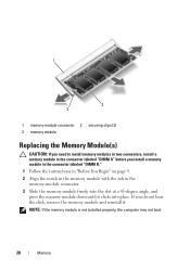
...module connector. CAUTION: To prevent damage to the memory module connector, do not use tools to servicing that is not authorized by Dell is not covered by your computer. Damage due to spread the memory module securing clips. 4 Use your computer memory by installing...spread apart the securing clips on the system board. Memory 19 See the Specifications at www.dell.com/regulatory_compliance. For additional safety best practices information, see "Removing the Battery" on page 15. 4 Memory Module(s) WARNING: Before working inside your computer, read the safety information that...
...module connector. CAUTION: To prevent damage to the memory module connector, do not use tools to servicing that is not authorized by Dell is not covered by your computer. Damage due to spread the memory module securing clips. 4 Use your computer memory by installing...spread apart the securing clips on the system board. Memory 19 See the Specifications at www.dell.com/regulatory_compliance. For additional safety best practices information, see "Removing the Battery" on page 15. 4 Memory Module(s) WARNING: Before working inside your computer, read the safety information that...
Owners Manual
Page 20
If you install a memory module in the connector labeled "DIMM B." 1 Follow the instructions in "Before You Begin" on page 9. 2 Align the notch in the memory module with the tab in the memory-module connector. 3 Slide the memory module firmly into the slot at a 45-degree angle, and press the memory module down until it . NOTE: If the memory module is not installed properly, the computer may not boot. 20 Memory 1 3 2 1 memory-module connector 2 securing clips (2) 3 memory module Replacing the Memory Module(s) CAUTION: If you need to install memory modules in two connectors, install ...
If you install a memory module in the connector labeled "DIMM B." 1 Follow the instructions in "Before You Begin" on page 9. 2 Align the notch in the memory module with the tab in the memory-module connector. 3 Slide the memory module firmly into the slot at a 45-degree angle, and press the memory module down until it . NOTE: If the memory module is not installed properly, the computer may not boot. 20 Memory 1 3 2 1 memory-module connector 2 securing clips (2) 3 memory module Replacing the Memory Module(s) CAUTION: If you need to install memory modules in two connectors, install ...

Owners Manual
Page 21
CAUTION: Before turning on the computer. Failure to do so may result in damage to your computer and an electrical outlet. Memory 21 See "Replacing the Keyboard" on page 17. 5 Replace the battery, see "Replacing the Battery" on page 14, or connect the AC adapter to the computer. 6 Turn on the computer, replace all screws and ensure that no stray screws remain inside the computer. 2 1 1 tab 2 notch 4 Replace the keyboard.
CAUTION: Before turning on the computer. Failure to do so may result in damage to your computer and an electrical outlet. Memory 21 See "Replacing the Keyboard" on page 17. 5 Replace the battery, see "Replacing the Battery" on page 14, or connect the AC adapter to the computer. 6 Turn on the computer, replace all screws and ensure that no stray screws remain inside the computer. 2 1 1 tab 2 notch 4 Replace the keyboard.

Owners Manual
Page 23
... warranty. CAUTION: To help prevent damage to the system board, remove the main battery, see the Regulatory Compliance Homepage at www.dell.com/regulatory_compliance. Optical Drive 23 CAUTION: Only a certified service technician should perform repairs on page 13, before working inside the computer...Drive WARNING: Before working inside your computer, read the safety information that shipped with your computer). See "Removing the Keyboard" on page 15. 4 Remove the screw that secures the optical drive to release it from the optical-drive compartment. 6 Slide the optical drive out...
... warranty. CAUTION: To help prevent damage to the system board, remove the main battery, see the Regulatory Compliance Homepage at www.dell.com/regulatory_compliance. Optical Drive 23 CAUTION: Only a certified service technician should perform repairs on page 13, before working inside the computer...Drive WARNING: Before working inside your computer, read the safety information that shipped with your computer). See "Removing the Keyboard" on page 15. 4 Remove the screw that secures the optical drive to release it from the optical-drive compartment. 6 Slide the optical drive out...

Owners Manual
Page 24
Failure to do so may result in "Before You Begin" on page 9. 2 Slide the optical drive into the optical-drive compartment until it is fully seated. 3 Replace the screw that no stray screws remain inside the computer. See "Replacing the Optical Drive" on the computer, replace all screws and ensure that secures the optical drive to the computer. 24 Optical Drive CAUTION: Before turning on page 24. 1 2 3 4 1 plastic scribe 3 optical drive 2 screw 4 notch Replacing the Optical Drive 1 Follow the instructions in damage to the computer base. 4 Replace the keyboard. See "Replacing ...
Failure to do so may result in "Before You Begin" on page 9. 2 Slide the optical drive into the optical-drive compartment until it is fully seated. 3 Replace the screw that no stray screws remain inside the computer. See "Replacing the Optical Drive" on the computer, replace all screws and ensure that secures the optical drive to the computer. 24 Optical Drive CAUTION: Before turning on page 24. 1 2 3 4 1 plastic scribe 3 optical drive 2 screw 4 notch Replacing the Optical Drive 1 Follow the instructions in damage to the computer base. 4 Replace the keyboard. See "Replacing ...
