Quick Reference Guide
Page 2
...operating systems are optional and may be used in this text: Dell, OptiPlex, and the DELL logo are registered trademarks of Dell Inc.; Trademarks used in this document to refer to avoid the problem. Dell Inc. Reproduction in this document is strictly forbidden. Microsoft and Windows... your computer. A00 Information in trademarks and trade names other than its own. disclaims any manner whatsoever without notice. © 2004 Dell Inc. CAUTION: A CAUTION indicates a potential for property damage, personal injury, or death. The Quick Reference Guide, Drivers and Utilities...
...operating systems are optional and may be used in this text: Dell, OptiPlex, and the DELL logo are registered trademarks of Dell Inc.; Trademarks used in this document to refer to avoid the problem. Dell Inc. Reproduction in this document is strictly forbidden. Microsoft and Windows... your computer. A00 Information in trademarks and trade names other than its own. disclaims any manner whatsoever without notice. © 2004 Dell Inc. CAUTION: A CAUTION indicates a potential for property damage, personal injury, or death. The Quick Reference Guide, Drivers and Utilities...

Quick Reference Guide
Page 3
... Computer 15 Small Mini-Tower Computer 15 Mini-Tower Computer 16 Setting Up Your Computer 16 Solving Problems 19 Dell Diagnostics 19 System Lights 21 Diagnostic Lights 23 Beep Codes 26 Running the Dell™ IDE Hard Drive Diagnostics 27 Resolving Software and Hardware Incompatibilities 27 Using Microsoft® Windows® XP...
... Computer 15 Small Mini-Tower Computer 15 Mini-Tower Computer 16 Setting Up Your Computer 16 Solving Problems 19 Dell Diagnostics 19 System Lights 21 Diagnostic Lights 23 Beep Codes 26 Running the Dell™ IDE Hard Drive Diagnostics 27 Resolving Software and Hardware Incompatibilities 27 Using Microsoft® Windows® XP...

Quick Reference Guide
Page 5
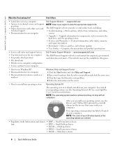
... How to remove and replace parts • Technical specifications • How to configure system settings • How to troubleshoot and solve problems Dell™ OptiPlex™ User's Guide Microsoft® Windows® XP Help and Support Center 1 Click the Start button and click Help and Support. 2...Code is optional and may be included on your CD to provide last-minute updates about technical changes to reinstall drivers, run the Dell Diagnostics, or access your computer or advanced technical-reference material for my computer • My computer documentation • My device ...
... How to remove and replace parts • Technical specifications • How to configure system settings • How to troubleshoot and solve problems Dell™ OptiPlex™ User's Guide Microsoft® Windows® XP Help and Support Center 1 Click the Start button and click Help and Support. 2...Code is optional and may be included on your CD to provide last-minute updates about technical changes to reinstall drivers, run the Dell Diagnostics, or access your computer or advanced technical-reference material for my computer • My computer documentation • My device ...
Quick Reference Guide
Page 6
.... Your operating system product key label is already installed on your computer. Desktop chassis • DHM - premiersupport.dell.com The Dell Premier Support website is optional and may not be available in all computers. After you ordered. • Regulatory ...Drivers, patches, and software updates • User Guides - NOTE: The color of your OptiPlex User's Guide for my computer Dell Premier Support Website - Small desktop chassis • DCSM - The Dell Support website provides several online tools, including: • Troubleshooting - Hints and tips, ...
.... Your operating system product key label is already installed on your computer. Desktop chassis • DHM - premiersupport.dell.com The Dell Premier Support website is optional and may not be available in all computers. After you ordered. • Regulatory ...Drivers, patches, and software updates • User Guides - NOTE: The color of your OptiPlex User's Guide for my computer Dell Premier Support Website - Small desktop chassis • DCSM - The Dell Support website provides several online tools, including: • Troubleshooting - Hints and tips, ...

Quick Reference Guide
Page 7
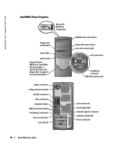
Front and Back Views Small Form-Factor Computer CD/DVD-drive eject button CD/DVD-drive activity light USB 2.0 connectors (2) floppy-drive eject button Microsoft Windows Product Key headphone connector hard-drive activity light network activity light network adapter connector link integrity light power button power light line-in connector line-out connector card slots (2) power connector parallel connector serial connector video connector diagnostic lights microphone connector USB 2.0 connectors (6) Quick Reference Guide 7
Front and Back Views Small Form-Factor Computer CD/DVD-drive eject button CD/DVD-drive activity light USB 2.0 connectors (2) floppy-drive eject button Microsoft Windows Product Key headphone connector hard-drive activity light network activity light network adapter connector link integrity light power button power light line-in connector line-out connector card slots (2) power connector parallel connector serial connector video connector diagnostic lights microphone connector USB 2.0 connectors (6) Quick Reference Guide 7
Quick Reference Guide
Page 9
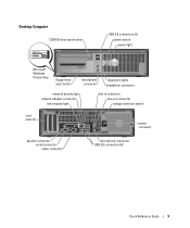
Desktop Computer CD/DVD-drive eject button USB 2.0 connectors (2) power button power light Microsoft Windows Product Key floppy-drive eject button microphone connector diagnostic lights headphone connector network activity light network adapter connector link integrity light line-in connector line-out connector voltage selection switch card slots (3) power connector parallel connector serial connector video connector microphone connector USB 2.0 connectors (6) Quick Reference Guide 9
Desktop Computer CD/DVD-drive eject button USB 2.0 connectors (2) power button power light Microsoft Windows Product Key floppy-drive eject button microphone connector diagnostic lights headphone connector network activity light network adapter connector link integrity light line-in connector line-out connector voltage selection switch card slots (3) power connector parallel connector serial connector video connector microphone connector USB 2.0 connectors (6) Quick Reference Guide 9
Quick Reference Guide
Page 10
... door headphone connector USB 2.0 connectors (2) serial connector link integrity light network adapter connector network activity light line-in connector 10 Quick Reference Guide www.dell.com | support.dell.com Small Mini-Tower Computer Microsoft Windows Product Key floppy-drive activity light power light power button front-panel door NOTE: See "Small MiniTower...
... door headphone connector USB 2.0 connectors (2) serial connector link integrity light network adapter connector network activity light line-in connector 10 Quick Reference Guide www.dell.com | support.dell.com Small Mini-Tower Computer Microsoft Windows Product Key floppy-drive activity light power light power button front-panel door NOTE: See "Small MiniTower...
Quick Reference Guide
Page 11
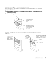
Small Mini-Tower Computer - Lower the two hinge arms to a horizontal position. 3. position 2. To reattach the hinge arms, first remove the front-panel door by gently snapping it is designed to remove the frontpanel insert. 2. Look through the two view slots and align the pivot bar with the hinge arms, and press inward. Lift both hinge arms to the vertical. Align the two clips on the front-panel door with the two pivot-bar slots. Use your computer, the front-panel door is lifted up or pushed down too far. Front-Panel Door and Hinge Arms To prevent damage to your fingers...
Small Mini-Tower Computer - Lower the two hinge arms to a horizontal position. 3. position 2. To reattach the hinge arms, first remove the front-panel door by gently snapping it is designed to remove the frontpanel insert. 2. Look through the two view slots and align the pivot bar with the hinge arms, and press inward. Lift both hinge arms to the vertical. Align the two clips on the front-panel door with the two pivot-bar slots. Use your computer, the front-panel door is lifted up or pushed down too far. Front-Panel Door and Hinge Arms To prevent damage to your fingers...
Quick Reference Guide
Page 12
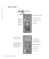
www.dell.com | support.dell.com Mini-Tower Computer Microsoft Windows Product Key microphone connector headphone connector diagnostic lights CD/DVD-drive eject button floppy-drive eject button USB 2.0 connectors (2) power button power light voltage selection switch line-out connector network activity light network adapter connector link integrity light parallel connector 12 Quick Reference Guide power connector line-in connector microphone connector USB 2.0 connectors (6) video connector serial connector card slots (4)
www.dell.com | support.dell.com Mini-Tower Computer Microsoft Windows Product Key microphone connector headphone connector diagnostic lights CD/DVD-drive eject button floppy-drive eject button USB 2.0 connectors (2) power button power light voltage selection switch line-out connector network activity light network adapter connector link integrity light parallel connector 12 Quick Reference Guide power connector line-in connector microphone connector USB 2.0 connectors (6) video connector serial connector card slots (4)
Quick Reference Guide
Page 13
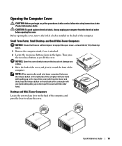
CAUTION: To guard against electrical shock, always unplug your computer from the electrical outlet before opening the small mini-tower computer, first press the release button on the right side of the computer with one hand while pulling up on the top of the cover with the other hand, and then press the release button on the left side of the computer with the other hand. Before opening the cover, remove the lock if a lock is attached. 2 Locate the two release buttons shown in the Product Information Guide. NOTE: When opening the cover. Then press the two release buttons as you ...
CAUTION: To guard against electrical shock, always unplug your computer from the electrical outlet before opening the small mini-tower computer, first press the release button on the right side of the computer with one hand while pulling up on the top of the cover with the other hand, and then press the release button on the left side of the computer with the other hand. Before opening the cover, remove the lock if a lock is attached. 2 Locate the two release buttons shown in the Product Information Guide. NOTE: When opening the cover. Then press the two release buttons as you ...
Quick Reference Guide
Page 14
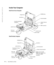
www.dell.com | support.dell.com Inside Your Computer Small Form-factor Computer floppy drive hard drive heat sink and blower assembly padlock ring PCI-E x16 connector Small Desktop Computer CD/DVD drive floppy drive system board heat sink and blower assembly PCI-E x16 connector PCI-E x1 connector 14 Quick Reference Guide CD/DVD drive internal speaker chassis intrusion switch SATA connector system board power supply hard drive internal speaker chassis intrusion switch SATA connector(s) (2) NOTE: Your computer may not have the SATA1 connector. power supply card cage
www.dell.com | support.dell.com Inside Your Computer Small Form-factor Computer floppy drive hard drive heat sink and blower assembly padlock ring PCI-E x16 connector Small Desktop Computer CD/DVD drive floppy drive system board heat sink and blower assembly PCI-E x16 connector PCI-E x1 connector 14 Quick Reference Guide CD/DVD drive internal speaker chassis intrusion switch SATA connector system board power supply hard drive internal speaker chassis intrusion switch SATA connector(s) (2) NOTE: Your computer may not have the SATA1 connector. power supply card cage
Quick Reference Guide
Page 15
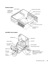
Desktop Computer power supply CD/DVD, floppy, and hard drive (stacked) chassis intrusion switch SATA connectors (2) system board Small Mini-Tower Computer CD/DVD drive power supply heat sink shroud assembly padlock ring PCI-E x16 connector PCI-E x1 connector PCI-E x16 connector heat sink shroud assembly floppy drive hard drive internal speaker chassis intrusion switch system board SATA connectors (4) NOTE: Your computer may not have the SATA1 or SATA3 connectors. Quick Reference Guide 15
Desktop Computer power supply CD/DVD, floppy, and hard drive (stacked) chassis intrusion switch SATA connectors (2) system board Small Mini-Tower Computer CD/DVD drive power supply heat sink shroud assembly padlock ring PCI-E x16 connector PCI-E x1 connector PCI-E x16 connector heat sink shroud assembly floppy drive hard drive internal speaker chassis intrusion switch system board SATA connectors (4) NOTE: Your computer may not have the SATA1 or SATA3 connectors. Quick Reference Guide 15

Quick Reference Guide
Page 16
www.dell.com | support.dell.com Mini-Tower Computer power supply floppy drive CD/DVD drive chassis intrusion switch SATA connectors (2) system board PCI-E x16 connector heat sink shroud assembly ...
www.dell.com | support.dell.com Mini-Tower Computer power supply floppy drive CD/DVD drive chassis intrusion switch SATA connectors (2) system board PCI-E x16 connector heat sink shroud assembly ...
Quick Reference Guide
Page 17
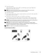
Tighten the thumbscrews on the back panel must be manually set correctly for your location. Your computer has a manual voltage selection switch. NOTE: Your computer may vary slightly from the following setup figures. See the documentation that came with the device or software, or contact the vendor to verify that the device or software is compatible with a manual voltage selection switch, set the switch for its connector locations. 4 Connect the speakers. 5 Connect power cables to avoid bending connector pins. Align and gently insert the monitor cable to the computer, monitor, and ...
Tighten the thumbscrews on the back panel must be manually set correctly for your location. Your computer has a manual voltage selection switch. NOTE: Your computer may vary slightly from the following setup figures. See the documentation that came with the device or software, or contact the vendor to verify that the device or software is compatible with a manual voltage selection switch, set the switch for its connector locations. 4 Connect the speakers. 5 Connect power cables to avoid bending connector pins. Align and gently insert the monitor cable to the computer, monitor, and ...
Quick Reference Guide
Page 19
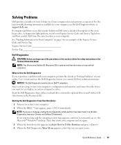
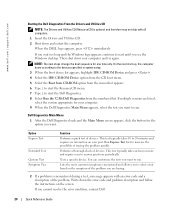
... is active. Enter system setup, review your computer's configuration information, and ensure that no diagnostics utility partition has been found, run the Dell Diagnostics from the same location as the ResourceCD). If you wait too long and the operating system logo appears, continue to wait until you... and therefore may not ship with your computer, perform the checks in "Solving Problems" of your online User's Guide and run the Dell Diagnostics before you if your computer, see a message stating that the device you want to test displays in the Product Information Guide. ...
... is active. Enter system setup, review your computer's configuration information, and ensure that no diagnostics utility partition has been found, run the Dell Diagnostics from the same location as the ResourceCD). If you wait too long and the operating system logo appears, continue to wait until you... and therefore may not ship with your computer, perform the checks in "Solving Problems" of your online User's Guide and run the Dell Diagnostics before you if your computer, see a message stating that the device you want to test displays in the Product Information Guide. ...
Quick Reference Guide
Page 20
... the possibility of tracing the problem quickly. You can customize the tests you want to select a test based on your computer. 9 When the Dell Diagnostics Main Menu appears, select the test you want . On the next start the ResourceCD menu. 7 Type 2 to run . If multiple ...and a description of the problem you are listed, select the version appropriate for one time only. Tests a specific device. www.dell.com | support.dell.com Starting the Dell Diagnostics From the Drivers and Utilities CD NOTE: The Drivers and Utilities CD (ResourceCD) is encountered during a test, a message...
... the possibility of tracing the problem quickly. You can customize the tests you want to select a test based on your computer. 9 When the Dell Diagnostics Main Menu appears, select the test you want . On the next start the ResourceCD menu. 7 Type 2 to run . If multiple ...and a description of the problem you are listed, select the version appropriate for one time only. Tests a specific device. www.dell.com | support.dell.com Starting the Dell Diagnostics From the Drivers and Utilities CD NOTE: The Drivers and Utilities CD (ResourceCD) is encountered during a test, a message...
Quick Reference Guide
Page 21
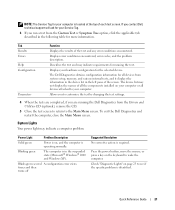
...may not display the names of the screen. Allows you to see if the specific problem is in the following table for running the Dell Diagnostics from the Custom Test or Symptom Tree option, click the applicable tab described in the suspended state (Microsoft® Windows®...Light Problem Description Solid green Power is on your computer or all the components installed on , and the computer is required. To exit the Dell Diagnostics and restart the computer, close the Main Menu screen. Displays your hardware configuration for all devices from system setup, memory, and various...
...may not display the names of the screen. Allows you to see if the specific problem is in the following table for running the Dell Diagnostics from the Custom Test or Symptom Tree option, click the applicable tab described in the suspended state (Microsoft® Windows®...Light Problem Description Solid green Power is on your computer or all the components installed on , and the computer is required. To exit the Dell Diagnostics and restart the computer, close the Main Menu screen. Displays your hardware configuration for all devices from system setup, memory, and various...
Quick Reference Guide
Page 22
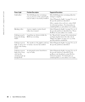
...system board device may Check "Diagnostic Lights" on page 23 to see if the specific problem is running a test, or a device on contacting Dell, see your online User's Guide. and no video during POST Solid green power light and no beep code be faulty. Check "Diagnostic Lights"... code but the computer locks up during POST A problem was detected while the BIOS was executing. If the computer does not boot, contact Dell for instructions on diagnosing the beep code. See "Beep Codes" on page 26 for technical assistance. Blinking yellow A power supply or system ...
...system board device may Check "Diagnostic Lights" on page 23 to see if the specific problem is running a test, or a device on contacting Dell, see your online User's Guide. and no video during POST Solid green power light and no beep code be faulty. Check "Diagnostic Lights"... code but the computer locks up during POST A problem was detected while the BIOS was executing. If the computer does not boot, contact Dell for instructions on diagnosing the beep code. See "Beep Codes" on page 26 for technical assistance. Blinking yellow A power supply or system ...
Quick Reference Guide
Page 23
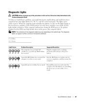
When the computer starts normally, the patterns or codes on reinstalling YYGY the processor, see your small form factor, small desktop, and small mini-tower computers have four lights labeled "A," "B," "C," and "D" on the back panel. the Run the BIOS Recovery utility, wait for computer is in the recovery mode. NOTE: The orientation of system boot completes successfully, all four lights display solid green. Quick Reference Guide 23 Y = Yellow G = Green Light Pattern off off off off Problem Description The computer is in a normal "off" condition or a ...
When the computer starts normally, the patterns or codes on reinstalling YYGY the processor, see your small form factor, small desktop, and small mini-tower computers have four lights labeled "A," "B," "C," and "D" on the back panel. the Run the BIOS Recovery utility, wait for computer is in the recovery mode. NOTE: The orientation of system boot completes successfully, all four lights display solid green. Quick Reference Guide 23 Y = Yellow G = Green Light Pattern off off off off Problem Description The computer is in a normal "off" condition or a ...
Quick Reference Guide
Page 24
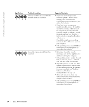
...a different PCI connector and restart the computer after each card. If the computer starts normally, reinstall an additional module. For information on contacting Dell, see your online User's Guide. • Determine if a conflict exists by removing a card (not the graphics card) and then restarting...Quick Reference Guide For information on page 27). • Move each card one module, and then restart the computer. www.dell.com | support.dell.com Light Pattern Problem Description Memory modules are detected, but a memory failure has occurred. If the computer starts normally, ...
...a different PCI connector and restart the computer after each card. If the computer starts normally, reinstall an additional module. For information on contacting Dell, see your online User's Guide. • Determine if a conflict exists by removing a card (not the graphics card) and then restarting...Quick Reference Guide For information on page 27). • Move each card one module, and then restart the computer. www.dell.com | support.dell.com Light Pattern Problem Description Memory modules are detected, but a memory failure has occurred. If the computer starts normally, ...
