Setup Guide
Page 4
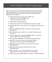
.../switch connection ❑ 1-meter copper Fibre Channel DB9-DB9 cable (1 per SP) for external disks on site already. ❑ FC4700 Disk Processor Enclosure (DPE) with • Minimum of nine hard disk drives • Two storage processors (SP) ❑ Standby Power Supply (SPS) (2) ❑ Null modem cable (1) for initialization with service laptop ❑ Modem 10baseT...
.../switch connection ❑ 1-meter copper Fibre Channel DB9-DB9 cable (1 per SP) for external disks on site already. ❑ FC4700 Disk Processor Enclosure (DPE) with • Minimum of nine hard disk drives • Two storage processors (SP) ❑ Standby Power Supply (SPS) (2) ❑ Null modem cable (1) for initialization with service laptop ❑ Modem 10baseT...

Setup Guide
Page 5
Storage processor B (SP-B) DAE DAE DAE DPE Storage processor A (SP-A) Rear of the following site and configuration preparations before you must connect each power outlet to accommodate the cabinet's two 240-volt ac power cables. Confirm that electrical wiring is in place at your FC4700 system. Before You Start IMPORTANT Be sure you have completed all of the FC4700 high-availability features, you attempt to set up your facility to a different circuit. 3 To support all of cabinet Standby power supply A (SPS-A) Standby power supply B (SPS-B) EMC1990 1.
Storage processor B (SP-B) DAE DAE DAE DPE Storage processor A (SP-A) Rear of the following site and configuration preparations before you must connect each power outlet to accommodate the cabinet's two 240-volt ac power cables. Confirm that electrical wiring is in place at your FC4700 system. Before You Start IMPORTANT Be sure you have completed all of the FC4700 high-availability features, you attempt to set up your facility to a different circuit. 3 To support all of cabinet Standby power supply A (SPS-A) Standby power supply B (SPS-B) EMC1990 1.

Setup Guide
Page 6
... network wiring for each storage processor (SP) requires a separate network connection. 3. Before You Start (continued) 2. Make sure that your environment includes switches on the path between the FC4700 and the hosts (servers) that the Standby Power Supplies (SPSs), Disk Processor Enclosure (DPE), and any... EMC Navisphere Event Monitor Administrator's Guide, and the appropriate Release Notes as the Navisphere management station. To manage the storage system, each switch. 4. Refer to the device-specific installation manuals for your cabinet. Have the network administrator at your...
... network wiring for each storage processor (SP) requires a separate network connection. 3. Before You Start (continued) 2. Make sure that your environment includes switches on the path between the FC4700 and the hosts (servers) that the Standby Power Supplies (SPSs), Disk Processor Enclosure (DPE), and any... EMC Navisphere Event Monitor Administrator's Guide, and the appropriate Release Notes as the Navisphere management station. To manage the storage system, each switch. 4. Refer to the device-specific installation manuals for your cabinet. Have the network administrator at your...
Setup Guide
Page 8
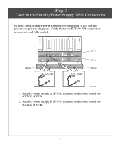
Standby power supply B (SPS-B) connects to shipment. Verify that your FC4700 SPS connections are connected to the storage processors prior to the lower serial port (COM2) of SP-A. 2. SPS-A COM2 SP-B COM2 SP-A SPS-B EMC1994 1. Step 3 Confirm the Standby Power Supply (SPS) Connections In most cases, standby power supplies are correct and fully seated. Standby power supply A (SPS-A) connects to the lower serial port (COM2) of SP-B. 6
Standby power supply B (SPS-B) connects to shipment. Verify that your FC4700 SPS connections are connected to the storage processors prior to the lower serial port (COM2) of SP-A. 2. SPS-A COM2 SP-B COM2 SP-A SPS-B EMC1994 1. Step 3 Confirm the Standby Power Supply (SPS) Connections In most cases, standby power supplies are correct and fully seated. Standby power supply A (SPS-A) connects to the lower serial port (COM2) of SP-B. 6

Setup Guide
Page 14
... cable. 2. Plug the cables into the SP host ports. 3. to : • Direct attach - Connect the other end of the Port 0 (top) cable to a storage processor (SP) host port on the remote storage system. 12 NOTE If the HBA is not yet installed in the host server, complete Step 9, then connect the SP. •...
... cable. 2. Plug the cables into the SP host ports. 3. to : • Direct attach - Connect the other end of the Port 0 (top) cable to a storage processor (SP) host port on the remote storage system. 12 NOTE If the HBA is not yet installed in the host server, complete Step 9, then connect the SP. •...


