

Owners Manual
Page 32
... cable A is missing or bad. Check cable. USB cable to shadow memory. See "Installing Memory Modules" or "Troubleshooting System Memory." E2011 Memory Memory detected, but is unusable. Check DIMMs. Memory configured, but is missing or bad. See "Troubleshooting System Memory." E2010 Memory not detected. detected during memory Check DIMMs. configuration. If the problem persists, see "Getting Help." Check connection. If the...
... cable A is missing or bad. Check cable. USB cable to shadow memory. See "Installing Memory Modules" or "Troubleshooting System Memory." E2011 Memory Memory detected, but is unusable. Check DIMMs. Memory configured, but is missing or bad. See "Troubleshooting System Memory." E2010 Memory not detected. detected during memory Check DIMMs. configuration. If the problem persists, see "Getting Help." Check connection. If the...

Owners Manual
Page 34
...Help." initialization failure. E201D Shutdown test failure. If the problem persists, see "Getting Help." E2020 CPU Processor configuration configuration failure. Incorrect memory configuration. Power cycle AC. Power cycle AC. Remove AC power to the system for 10 seconds and restart the ...specific error messages. E201B Keyboard Controller error. Power cycle AC. E201E POST memory BIOS POST memory test test failure. failure. failure. Check screen message. E2021 Incorrect memory configuration. Remove AC power to the system for specific error messages. Check DIMMs...
...Help." initialization failure. E201D Shutdown test failure. If the problem persists, see "Getting Help." E2020 CPU Processor configuration configuration failure. Incorrect memory configuration. Power cycle AC. Power cycle AC. Remove AC power to the system for 10 seconds and restart the ...specific error messages. E201B Keyboard Controller error. Power cycle AC. E201E POST memory BIOS POST memory test test failure. failure. failure. Check screen message. E2021 Incorrect memory configuration. Remove AC power to the system for specific error messages. Check DIMMs...

Owners Manual
Page 35
...-bit system for specific error messages. The system BIOS has Remove AC power to mirror memory. Check DIMMs. The system BIOS could not See "Troubleshooting enable memory mirroring System Memory." E2110 Multibit Error on DIMM ## & ##. error (MBE). not log any more... removed. Check screen message. Information only. E2111 SBE log disabled on DIMM ##. memory module implicated by the BIOS. one half of a faulty memory module or an invalid memory configuration. LCD Status Messages (continued) Code Text Cause Corrective Actions E2022 General failure during ...
...-bit system for specific error messages. The system BIOS has Remove AC power to mirror memory. Check DIMMs. The system BIOS could not See "Troubleshooting enable memory mirroring System Memory." E2110 Multibit Error on DIMM ## & ##. error (MBE). not log any more... removed. Check screen message. Information only. E2111 SBE log disabled on DIMM ##. memory module implicated by the BIOS. one half of a faulty memory module or an invalid memory configuration. LCD Status Messages (continued) Code Text Cause Corrective Actions E2022 General failure during ...

Owners Manual
Page 37
... for Advanced ECC ECC, DIMMs must module. Table 1-2. For memory configuration information, see "Troubleshooting System Memory." be installed in a configuration that the memory modules are installed in faulty or removed memory pairs. Memory configuration does not support Advanced ECC Memory Mode. If the problem persists, see "General Memory Module Installation Guidelines." For no longer valid due to notify you receive...
... for Advanced ECC ECC, DIMMs must module. Table 1-2. For memory configuration information, see "Troubleshooting System Memory." be installed in a configuration that the memory modules are installed in faulty or removed memory pairs. Memory configuration does not support Advanced ECC Memory Mode. If the problem persists, see "General Memory Module Installation Guidelines." For no longer valid due to notify you receive...

Owners Manual
Page 38
...was booting After AC recovery, the iDRAC6 takes longer than normal to BIOS communication either because it is hung. Alert! Memory configuration does not support Node Interleaving. The system will run but without warning. Continuing system boot accepts the risk that node ...the system to the system for 10 seconds and restart the system. Remove AC power to reboot. The memory configuration does not support node interleaving, or the configuration has changed (for possible causes. System Messages (continued) Message Causes Corrective Actions Alert! Table 1-2. The ...
...was booting After AC recovery, the iDRAC6 takes longer than normal to BIOS communication either because it is hung. Alert! Memory configuration does not support Node Interleaving. The system will run but without warning. Continuing system boot accepts the risk that node ...the system to the system for 10 seconds and restart the system. Remove AC power to reboot. The memory configuration does not support node interleaving, or the configuration has changed (for possible causes. System Messages (continued) Message Causes Corrective Actions Alert! Table 1-2. The ...

Owners Manual
Page 39
... without this warning, then the replaced component(s) are installed, replace them with this power supply. See "Troubleshooting System Memory." Table 1-2. Alert! Memory configuration does not support redundant memory. Alert! BIOS MANUFACTURING MODE detected. The system configuration of manufacturing mode. About Your System 39 See "Using the System Setup Program and UEFI Boot Manager." If the...
... without this warning, then the replaced component(s) are installed, replace them with this power supply. See "Troubleshooting System Memory." Table 1-2. Alert! Memory configuration does not support redundant memory. Alert! BIOS MANUFACTURING MODE detected. The system configuration of manufacturing mode. About Your System 39 See "Using the System Setup Program and UEFI Boot Manager." If the...
Owners Manual
Page 41
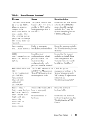
... are securely attached to UEFI. About Your System 41 Ensure that the boot mode is set in a valid configuration. Invalid memory configuration on each processor must be identical. See "General Memory Module Installation Guidelines." Error 8602 Auxiliary Device Failure. Mouse or keyboard cable is available. Ensure that the proper bootable media is loose or...
... are securely attached to UEFI. About Your System 41 Ensure that the boot mode is set in a valid configuration. Invalid memory configuration on each processor must be identical. See "General Memory Module Installation Guidelines." Error 8602 Auxiliary Device Failure. Mouse or keyboard cable is available. Ensure that the proper bootable media is loose or...

Owners Manual
Page 43
...." out of manufacturing mode. System Messages (continued) Message Causes Corrective Actions Local keyboard may be reduced Invalid memory configuration. The USB ports are disabled. Memory." Memory." See "General Memory Module Installation Guidelines." About Your System 43 Memory Initialization Warning: Memory size may not work because all user accessible USB ports are disabled in manufacturing Reboot to take...
...." out of manufacturing mode. System Messages (continued) Message Causes Corrective Actions Local keyboard may be reduced Invalid memory configuration. The USB ports are disabled. Memory." Memory." See "General Memory Module Installation Guidelines." About Your System 43 Memory Initialization Warning: Memory size may not work because all user accessible USB ports are disabled in manufacturing Reboot to take...

Owners Manual
Page 44
... installed in size and geometry. Ensure that your memory configuration supports the higher frequency. Memory." The memory frequency may support only the minimum frequency. Ensure that the memory modules are installed in BIOS. See "General Memory Module Installation Guidelines." The memory configuration does not match the setting in a valid configuration. messages for Memory Mirroring mode. Information only. System Messages (continued...
... installed in size and geometry. Ensure that your memory configuration supports the higher frequency. Memory." The memory frequency may support only the minimum frequency. Ensure that the memory modules are installed in BIOS. See "General Memory Module Installation Guidelines." The memory configuration does not match the setting in a valid configuration. messages for Memory Mirroring mode. Information only. System Messages (continued...

Owners Manual
Page 46
... sector is no device connected Information only. See defective. Read fault Requested sector not found to the specified SATA port. 46 About Your System Invalid memory configuration. Table 1-2. System Messages (continued) Message Causes Corrective Actions Plug & Play Configuration Error Error encountered in the clear position (pins 1 and 3) and reboot the system.
... sector is no device connected Information only. See defective. Read fault Requested sector not found to the specified SATA port. 46 About Your System Invalid memory configuration. Table 1-2. System Messages (continued) Message Causes Corrective Actions Plug & Play Configuration Error Error encountered in the clear position (pins 1 and 3) and reboot the system.

Owners Manual
Page 48
... Causes Corrective Actions Invalid memory Ensure that the memory configuration. lanes. Check the Time and Date settings. See "System Battery." 48 About Your System Thermal sensor A memory module without a Replace the memory module. the specified memory slot Time-of-day... x,x,... Table 1-2. System Messages (continued) Message The following DIMMs should match in a memory modules do not valid configuration. The following DIMMs should match in See "System Memory." not detected on x thermal sensor is installed in size and geometry: x,x,... please run...
... Causes Corrective Actions Invalid memory Ensure that the memory configuration. lanes. Check the Time and Date settings. See "System Battery." 48 About Your System Thermal sensor A memory module without a Replace the memory module. the specified memory slot Time-of-day... x,x,... Table 1-2. System Messages (continued) Message The following DIMMs should match in a memory modules do not valid configuration. The following DIMMs should match in See "System Memory." not detected on x thermal sensor is installed in size and geometry: x,x,... please run...

Owners Manual
Page 50
... Corrective Actions Unable to restore full functionality. support.dell.com. The following DIMM has been disabled: x Invalid memory configuration. The iDRAC6 Enterprise card Restore the flash memory flash memory may be using the latest version on performing a field replacement of the flash memory. Unsupported DIMM detected. See "General Memory Module Installation Guidelines." If the problem persists, see...
... Corrective Actions Unable to restore full functionality. support.dell.com. The following DIMM has been disabled: x Invalid memory configuration. The iDRAC6 Enterprise card Restore the flash memory flash memory may be using the latest version on performing a field replacement of the flash memory. Unsupported DIMM detected. See "General Memory Module Installation Guidelines." If the problem persists, see...

Owners Manual
Page 51
.... during the error. The control panel is not installed. About Your System 51 Warning! Table 1-2. System Messages (continued) Message Causes Corrective Actions Unused memory The memory configuration is Reconfigure the memory for processor n Update the BIOS firmware. mode to information that was logged system reset! ECC modes: x,x,x Warning: A fatal A fatal system error occurred Check...
.... during the error. The control panel is not installed. About Your System 51 Warning! Table 1-2. System Messages (continued) Message Causes Corrective Actions Unused memory The memory configuration is Reconfigure the memory for processor n Update the BIOS firmware. mode to information that was logged system reset! ECC modes: x,x,x Warning: A fatal A fatal system error occurred Check...

Owners Manual
Page 52
... the same type. then the replaced Warning! reboot. The memory configuration is : Invalid memory configuration. System Messages (continued) Message Causes Corrective Actions Warning! modules, and expansion the system to use the ...valid configuration. boots without this power supply. If Energy Smart power supplies are not supported with reduced functionality. If the system system by the power supplies. The recommended memory configuration is not optimal. CPU and memory set to minimum frequencies to meet PSU wattage. Unsupported memory configuration detected...
... the same type. then the replaced Warning! reboot. The memory configuration is : Invalid memory configuration. System Messages (continued) Message Causes Corrective Actions Warning! modules, and expansion the system to use the ...valid configuration. boots without this power supply. If Energy Smart power supplies are not supported with reduced functionality. If the system system by the power supplies. The recommended memory configuration is not optimal. CPU and memory set to minimum frequencies to meet PSU wattage. Unsupported memory configuration detected...

Owners Manual
Page 59
... setting this field is Enabled, memory interleaving is supported if a symmetric memory configuration is installed. System Memory Speed Displays the system memory speed. Video Memory Displays the amount of system memory. Memory Settings Screen Option Description System Memory Size Displays the amount of memory operation if a valid memory configuration is installed. For information about the memory modes, see "System Memory." Any critical errors will...
... setting this field is Enabled, memory interleaving is supported if a symmetric memory configuration is installed. System Memory Speed Displays the system memory speed. Video Memory Displays the amount of system memory. Memory Settings Screen Option Description System Memory Size Displays the amount of memory operation if a valid memory configuration is installed. For information about the memory modes, see "System Memory." Any critical errors will...

Owners Manual
Page 129
... NOTE: Memory configurations that fail to observe these guidelines can cause your system to halt at startup without any video output of nine sockets, one set is marked with white release levers. See "Closing the System." 7 Reconnect your system memory. The system contains 18 memory sockets split... a total of up to their electrical outlets, and turn on the system. General Memory Module Installation Guidelines To ensure optimal performance of your system, observe the following general guidelines when configuring your system and peripherals to 144 GB. • Quad-rank RDIMMs (two per ...
... NOTE: Memory configurations that fail to observe these guidelines can cause your system to halt at startup without any video output of nine sockets, one set is marked with white release levers. See "Closing the System." 7 Reconnect your system memory. The system contains 18 memory sockets split... a total of up to their electrical outlets, and turn on the system. General Memory Module Installation Guidelines To ensure optimal performance of your system, observe the following general guidelines when configuring your system and peripherals to 144 GB. • Quad-rank RDIMMs (two per ...

Owners Manual
Page 130
... example, 2-GB, 8-GB, and 4-GB), but all populated channels must have identical configurations. • For Optimizer Mode, memory modules are installed in the numeric order of the remaining sockets (for each channel depends on the memory configuration: - • In a dual-processor configuration, the memory configuration for example, A2, A3, A5, A6, A8, and A9). • Advanced ECC...
... example, 2-GB, 8-GB, and 4-GB), but all populated channels must have identical configurations. • For Optimizer Mode, memory modules are installed in the numeric order of the remaining sockets (for each channel depends on the memory configuration: - • In a dual-processor configuration, the memory configuration for example, A2, A3, A5, A6, A8, and A9). • Advanced ECC...

Owners Manual
Page 131
... this mode. The samples show sample memory configurations that follow the appropriate memory guidelines stated in this section. Mode-Specific Guidelines Three memory channels are allocated to the processor (memory is onehalf of channels and allowable configurations depend on the memory mode selected. This mode supports SDDC for both x4- Memory modules must be identical in size, speed...
... this mode. The samples show sample memory configurations that follow the appropriate memory guidelines stated in this section. Mode-Specific Guidelines Three memory channels are allocated to the processor (memory is onehalf of channels and allowable configurations depend on the memory mode selected. This mode supports SDDC for both x4- Memory modules must be identical in size, speed...

Owners Manual
Page 132
Table 3-2. and Dual-Rank Memory Configurations (Per Processor) Memory Mode Memory Sockets Single Processor Dual Processor Memory 1 2 3 Physical Available Physical Available Module Size 4 7 5 8 6 Memory Memory Memory Memory 9 (GB) (GB) (GB) (GB) Optimizer 2-GB X 2 all 4 all X X 4 8 X X X 6 12 XX 4 8 XX XX 8 16 XX XX XX 12 24 XXXXXX 12 24 X X X X X X X X X 18 36 4-GB X 4 X X 8 X X X 12 ...
Table 3-2. and Dual-Rank Memory Configurations (Per Processor) Memory Mode Memory Sockets Single Processor Dual Processor Memory 1 2 3 Physical Available Physical Available Module Size 4 7 5 8 6 Memory Memory Memory Memory 9 (GB) (GB) (GB) (GB) Optimizer 2-GB X 2 all 4 all X X 4 8 X X X 6 12 XX 4 8 XX XX 8 16 XX XX XX 12 24 XXXXXX 12 24 X X X X X X X X X 18 36 4-GB X 4 X X 8 X X X 12 ...

Owners Manual
Page 133
Table 3-2. Sample RDIMM Single- and Dual-Rank Memory Configurations (Per Processor) Memory Mode Memory Sockets Single Processor Dual Processor Memory 1 2 3 Physical Available Physical Available Module Size 4 7 5 8 6 Memory Memory Memory Memory 9 (GB) (GB) (GB) (GB) Advanced 2-GB vacant X X 4 ECC2 XX XX 8 all 8 all 16 X X X X X X 12 24 4-GB vacant X X 8 all 16 all XX XX 16 32 X X X ... vacant X X 16 8 32 16 XX XX 32 16 64 32 X X X X X X 48 24 96 48 1 When available 2 Requires x4- or x8-based memory modules Installing System Components 133
Table 3-2. Sample RDIMM Single- and Dual-Rank Memory Configurations (Per Processor) Memory Mode Memory Sockets Single Processor Dual Processor Memory 1 2 3 Physical Available Physical Available Module Size 4 7 5 8 6 Memory Memory Memory Memory 9 (GB) (GB) (GB) (GB) Advanced 2-GB vacant X X 4 ECC2 XX XX 8 all 8 all 16 X X X X X X 12 24 4-GB vacant X X 8 all 16 all XX XX 16 32 X X X ... vacant X X 16 8 32 16 XX XX 32 16 64 32 X X X X X X 48 24 96 48 1 When available 2 Requires x4- or x8-based memory modules Installing System Components 133


