
EqualLogic PS4110 Storage Arrays - Installation and Setup Guide
Page 5
...: • Basic networking concepts • Current network environment • User disk storage requirements • RAID configurations • Disk storage management Note: Although this guide is beyond its scope. Organization This manual is organized as follows: • Chapter 1, Understanding the Array Installation Procedure describes the general steps for installing array hardware. With one or more efficiently. Technical Support and Customer Service Dell's support service is affordable and easy to install the array in this manual provides examples of...
...: • Basic networking concepts • Current network environment • User disk storage requirements • RAID configurations • Disk storage management Note: Although this guide is beyond its scope. Organization This manual is organized as follows: • Chapter 1, Understanding the Array Installation Procedure describes the general steps for installing array hardware. With one or more efficiently. Technical Support and Customer Service Dell's support service is affordable and easy to install the array in this manual provides examples of...
EqualLogic PS4110 Storage Arrays - Installation and Setup Guide
Page 6
... basic storage array information, maintenance information, and troubleshooting information, refer to the Hardware Owner's Manual for sales, technical support, or customer service issues: 1. For a listing of contacting Dell support, such as e-mail or telephone. Note: If you do not have access to contact Dell for your locale. Visit support.dell.com or the Dell support URL specified in any Dell product information). 2. Select the required service. Use the locale menu or click on the link...
... basic storage array information, maintenance information, and troubleshooting information, refer to the Hardware Owner's Manual for sales, technical support, or customer service issues: 1. For a listing of contacting Dell support, such as e-mail or telephone. Note: If you do not have access to contact Dell for your locale. Visit support.dell.com or the Dell support URL specified in any Dell product information). 2. Select the required service. Use the locale menu or click on the link...
EqualLogic PS4110 Storage Arrays - Installation and Setup Guide
Page 12
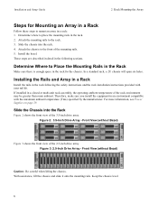
... enough space in the rack for Mounting an Array in the rack. 2. If installed in an environment compatible with your rail kit. Therefore, make sure you install the equipment in a closed or multi-unit rack assembly, the operating ambient temperature of the 2.5-inch drive array. For more information, see Power Supplies on page 29. Install the bezel. Installation and Setup Guide 2 Rack Mounting the Array Steps for the chassis. Determine where to the...
... enough space in the rack for Mounting an Array in the rack. 2. If installed in an environment compatible with your rail kit. Therefore, make sure you install the equipment in a closed or multi-unit rack assembly, the operating ambient temperature of the 2.5-inch drive array. For more information, see Power Supplies on page 29. Install the bezel. Installation and Setup Guide 2 Rack Mounting the Array Steps for the chassis. Determine where to the...

EqualLogic PS4110 Storage Arrays - Installation and Setup Guide
Page 18
... network connections are recommended for an adequate amount of power. Find the power switch, located below the power plug on power to ambient temperature (for more than a 4-inch bend radius at a time. Use the management port only if you configure a management network. The Type 17 control module contains two 10Gb Ethernet ports, both at the same time. 1. Note: Optical cables transmit data through pulses of copper or optical 10GbE network cables. See the Dell EqualLogic...
... network connections are recommended for an adequate amount of power. Find the power switch, located below the power plug on power to ambient temperature (for more than a 4-inch bend radius at a time. Use the management port only if you configure a management network. The Type 17 control module contains two 10Gb Ethernet ports, both at the same time. 1. Note: Optical cables transmit data through pulses of copper or optical 10GbE network cables. See the Dell EqualLogic...
EqualLogic PS4110 Storage Arrays - Installation and Setup Guide
Page 24
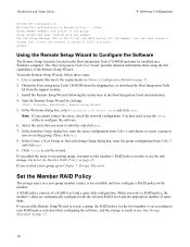
... array, check the network configuration. The Host Integration Tools User Guide provides detailed information about using an iSCSI initiator. In the Create a New Group or Join an Existing Group dialog box, enter the group configuration from the support website. 3. Waiting for the member. To run the Remote Setup Wizard, follow these steps: 1. A RAID policy consists of spare disks. If you configure a RAID policy on a Windows computer. Installation and Setup Guide 4 Software Configuration...
... array, check the network configuration. The Host Integration Tools User Guide provides detailed information about using an iSCSI initiator. In the Create a New Group or Join an Existing Group dialog box, enter the group configuration from the support website. 3. Waiting for the member. To run the Remote Setup Wizard, follow these steps: 1. A RAID policy consists of spare disks. If you configure a RAID policy on a Windows computer. Installation and Setup Guide 4 Software Configuration...

EqualLogic PS4110 Storage Arrays - Installation and Setup Guide
Page 38
...12 power requirements 4 PS Series array increasing bandwidth 9 network recommendations 9 network requirements 9 protecting from discharge 4 subnet access recommendation 10 R rack mount choosing rail location 6 inserting chassis 6 installing chassis 6 rail kit parts 5 requirements 3 RAID levels supported 18 RAID policy description 18 32 setting with CLI 19 setting with GUI 19 Remote Setup Wizard configuring the software 18 S safety precautions installation 3 serial cable characteristics 14 connecting 13 pin locations 14 pinout information 14 setup utility configuring the...
...12 power requirements 4 PS Series array increasing bandwidth 9 network recommendations 9 network requirements 9 protecting from discharge 4 subnet access recommendation 10 R rack mount choosing rail location 6 inserting chassis 6 installing chassis 6 rail kit parts 5 requirements 3 RAID levels supported 18 RAID policy description 18 32 setting with CLI 19 setting with GUI 19 Remote Setup Wizard configuring the software 18 S safety precautions installation 3 serial cable characteristics 14 connecting 13 pin locations 14 pinout information 14 setup utility configuring the...

PS4110 Hardware Owners Manual
Page 3
...Drive Types 7 Identifying Failed Drives 7 Interpreting Drive LEDs 8 Array Behavior When a Drive Fails 9 Drive Handling Requirements 9 Drive Installation Guidelines and Restrictions 10 3 Maintaining Control Modules 17 Control Module Features 17 Replacing a Control Module 24 Replacing the MicroSD Card 29 Advanced Networking Options 31 4 Maintaining Power Supply and Cooling Modules 33 About Power Supplies 33 Identifying Power Supply Failures 33 Removing a Power Supply and Cooling Module 35 Installing a Power Supply and Cooling Module 36 5 Troubleshooting Your Array...
...Drive Types 7 Identifying Failed Drives 7 Interpreting Drive LEDs 8 Array Behavior When a Drive Fails 9 Drive Handling Requirements 9 Drive Installation Guidelines and Restrictions 10 3 Maintaining Control Modules 17 Control Module Features 17 Replacing a Control Module 24 Replacing the MicroSD Card 29 Advanced Networking Options 31 4 Maintaining Power Supply and Cooling Modules 33 About Power Supplies 33 Identifying Power Supply Failures 33 Removing a Power Supply and Cooling Module 35 Installing a Power Supply and Cooling Module 36 5 Troubleshooting Your Array...

PS4110 Hardware Owners Manual
Page 11
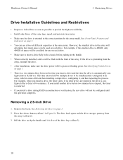
... keyed to a backplane through drive carriers and are numbered 0-23, left to right. • In arrays with 0 on your configuration, your array supports up to 24 2.5-inch SAS drives or up to bottom, starting with 3.5-inch drives (installed horizontally), the drives are connected to fit into specific array models, and cannot be installed in internal drive bays. Table 3 shows the drive order for that is indicated by: • LEDs on the console, in the event log...
... keyed to a backplane through drive carriers and are numbered 0-23, left to right. • In arrays with 0 on your configuration, your array supports up to 24 2.5-inch SAS drives or up to bottom, starting with 3.5-inch drives (installed horizontally), the drives are connected to fit into specific array models, and cannot be installed in internal drive bays. Table 3 shows the drive order for that is indicated by: • LEDs on the console, in the event log...
PS4110 Hardware Owners Manual
Page 14
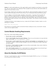
... Removing the Bezel on each drive. See Identifying Failed Drives on each drive. • Make sure to be simultaneously configured in the handle. • When correctly installed, a drive will be configured until it , and then repeating the process. For example, when you install a drive during RAID reconstruction or verification, the new drive will be available for the array model. Press the release button (callout 1 in the array...
... Removing the Bezel on each drive. See Identifying Failed Drives on each drive. • Make sure to be simultaneously configured in the handle. • When correctly installed, a drive will be configured until it , and then repeating the process. For example, when you install a drive during RAID reconstruction or verification, the new drive will be available for the array model. Press the release button (callout 1 in the array...

PS4110 Hardware Owners Manual
Page 22
... loses connectivity (switch 0 fails), Ethernet 0 on the secondary control module if a network path fails. See the latest PS Series Release Notes for replacement. Hardware Owner's Manual 3 Maintaining Control Modules • A release button and latch to release the control module from the active control module. If the control module fails, the entire array (and all access to your volumes stops until you time to replace the failed control module while your data. Dual Controller Configuration A dual control module configuration eliminates a single point of failure. Single...
... loses connectivity (switch 0 fails), Ethernet 0 on the secondary control module if a network path fails. See the latest PS Series Release Notes for replacement. Hardware Owner's Manual 3 Maintaining Control Modules • A release button and latch to release the control module from the active control module. If the control module fails, the entire array (and all access to your volumes stops until you time to replace the failed control module while your data. Dual Controller Configuration A dual control module configuration eliminates a single point of failure. Single...

PS4110 Hardware Owners Manual
Page 25
...Firmware A control module has a microSD card running the array firmware. When viewed from the corresponding port on both control modules are using a dedicated management network, make sure the management ports on the secondary control module to -flash module for storing recently-used data. Therefore, if you are connected to its own local network interface, or the network interface on the previously-active control module.) Control module failover is on the other (secondary) control module if a network path fails. See "Dual Controller Configuration" on page 3. Hardware Owner's Manual...
...Firmware A control module has a microSD card running the array firmware. When viewed from the corresponding port on both control modules are using a dedicated management network, make sure the management ports on the secondary control module to -flash module for storing recently-used data. Therefore, if you are connected to its own local network interface, or the network interface on the previously-active control module.) Control module failover is on the other (secondary) control module if a network path fails. See "Dual Controller Configuration" on page 3. Hardware Owner's Manual...
PS4110 Hardware Owners Manual
Page 26
...- chronization completes, a console message will be available in an anti-static bag or place the control module on a surface protected from electrostatic discharge. Hardware Owner's Manual 3 Maintaining Control Modules Caution: In a dual control module array, both control modules are updated to the same firmware version. Control Module Handling Requirements Follow these control module handling requirements: • Do not remove an active control module. • Protect control modules from electrostatic discharge. Inform your array support provider. The button is recessed to...
...- chronization completes, a console message will be available in an anti-static bag or place the control module on a surface protected from electrostatic discharge. Hardware Owner's Manual 3 Maintaining Control Modules Caution: In a dual control module array, both control modules are updated to the same firmware version. Control Module Handling Requirements Follow these control module handling requirements: • Do not remove an active control module. • Protect control modules from electrostatic discharge. Inform your array support provider. The button is recessed to...
PS4110 Hardware Owners Manual
Page 31
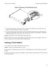
... down the array. Place the control module on page 29. If you are installed horizontally in the replacement control module. Return the failed control module in the packaging in an array. This will be protected from the failed control module and install it in the array, with an empty control module slot. Facing the rear of the control module. 4. Caution: Do not mix control module types in which the replacement module was shipped. Hardware Owner's Manual 3 Maintaining Control Modules Figure 17: Removing a Control Module (2U Array) 3.
... down the array. Place the control module on page 29. If you are installed horizontally in the replacement control module. Return the failed control module in the packaging in an array. This will be protected from the failed control module and install it in the array, with an empty control module slot. Facing the rear of the control module. 4. Caution: Do not mix control module types in which the replacement module was shipped. Hardware Owner's Manual 3 Maintaining Control Modules Figure 17: Removing a Control Module (2U Array) 3.
PS4110 Hardware Owners Manual
Page 33
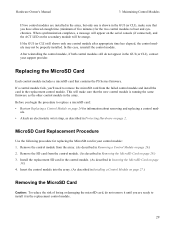
... array. Install the replacement SD card in the control module. (As described in the GUI (or CLI), contact your control module: 1. Remove the SD card from the array. (As described in Removing a Control Module on page 29.) 3. If a control module fails, you begin the procedure to replace a microSD card: • Review Replacing a Control Module on page 30.) 4. Before you 'll need to remove the microSD card from the failed control module and install the card in the replacement control module. Hardware Owner's Manual 3 Maintaining Control Modules If two control modules...
... array. Install the replacement SD card in the control module. (As described in the GUI (or CLI), contact your control module: 1. Remove the SD card from the array. (As described in Removing a Control Module on page 29.) 3. If a control module fails, you begin the procedure to replace a microSD card: • Review Replacing a Control Module on page 30.) 4. Before you 'll need to remove the microSD card from the failed control module and install the card in the replacement control module. Hardware Owner's Manual 3 Maintaining Control Modules If two control modules...
PS4110 Hardware Owners Manual
Page 44
..., check if: • The array fault LEDs are not solid green, see Control Module Features on page 17. • Make sure that is connected to customer support when you access the hard drive. See Obtaining Technical Sup- port and Customer Service on page 39. 40 If the problem is visible on the right bezel latch block. Hardware Owner's Manual 5 Troubleshooting Your Array Determining Service Tag Information Each array has a service tag with a number. See...
..., check if: • The array fault LEDs are not solid green, see Control Module Features on page 17. • Make sure that is connected to customer support when you access the hard drive. See Obtaining Technical Sup- port and Customer Service on page 39. 40 If the problem is visible on the right bezel latch block. Hardware Owner's Manual 5 Troubleshooting Your Array Determining Service Tag Information Each array has a service tag with a number. See...
PS4110 Hardware Owners Manual
Page 45
... back-panel connectors on your array. Troubleshooting Array Cooling Problems Check for the array in the Installation and Setup Guide. 41 A single power supply and cooling module can operate on page 35. Locate the faulty power supply and determine the status of the following situations: • Empty drive bays (no drive or drive blank). • Ambient temperature is working . - however both modules must be removed from a powered-on page 39. Troubleshooting Power Supply and Cooling Modules 1. The array can be installed to...
... back-panel connectors on your array. Troubleshooting Array Cooling Problems Check for the array in the Installation and Setup Guide. 41 A single power supply and cooling module can operate on page 35. Locate the faulty power supply and determine the status of the following situations: • Empty drive bays (no drive or drive blank). • Ambient temperature is working . - however both modules must be removed from a powered-on page 39. Troubleshooting Power Supply and Cooling Modules 1. The array can be installed to...

PS4110 Hardware Owners Manual
Page 46
... the control module port link status LED and the control module status LED are not solid green, see Obtaining Technical Support and Customer Service on page 39. See Replacing a Control Module on the backplane and control module are not green: a. See Interpreting Control Module LEDs on page 39. 42 See Troubleshooting Power Supply and Cool- If the problem is not resolved, see the PS Series Release Notes and the document Updating PS Series Storage Array Firmware, available on page 24. 2. Troubleshooting Hard Drives Check the hard drive...
... the control module port link status LED and the control module status LED are not solid green, see Obtaining Technical Support and Customer Service on page 39. See Replacing a Control Module on the backplane and control module are not green: a. See Interpreting Control Module LEDs on page 39. 42 See Troubleshooting Power Supply and Cool- If the problem is not resolved, see the PS Series Release Notes and the document Updating PS Series Storage Array Firmware, available on page 24. 2. Troubleshooting Hard Drives Check the hard drive...
PS4110 Hardware Owners Manual
Page 47
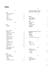
Index A array control module restriction control modules cooling fans firmware LEDs power supplies shutdown procedure B bezel installing removing C control modules batteries checking proper installation failover behavior failure indications features firmware requirements firmware version handling requirements installing in array LEDs locating removing from array restriction on mixing restrictions supported disk type synchronizing types verifying operational status cooling module removing PSU D disks failure behavior failure indications handling requirements LEDs locating protecting verifying ...
Index A array control module restriction control modules cooling fans firmware LEDs power supplies shutdown procedure B bezel installing removing C control modules batteries checking proper installation failover behavior failure indications features firmware requirements firmware version handling requirements installing in array LEDs locating removing from array restriction on mixing restrictions supported disk type synchronizing types verifying operational status cooling module removing PSU D disks failure behavior failure indications handling requirements LEDs locating protecting verifying ...
EqualLogic PS4110 Setup Poster
Page 1
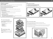
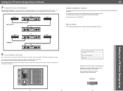
.... 2. Using the provided key, lock the front bezel. Mount the array in a Rack Warning! Note: Use separate sources of the chassis. 3. See the Installation Guide for complete installation information. Setting Up a PS Series Storage Array PS4110 Installation Before You Begin This is set to off (O) before connecting the power cables. 1. Standard 19-inch, four-post rack. - For Management connections (optional): CAT5 cable with the array model number and Dell logo upright. 2. See the rack instructions that came with the rail kit in RAID...
.... 2. Using the provided key, lock the front bezel. Mount the array in a Rack Warning! Note: Use separate sources of the chassis. 3. See the Installation Guide for complete installation information. Setting Up a PS Series Storage Array PS4110 Installation Before You Begin This is set to off (O) before connecting the power cables. 1. Standard 19-inch, four-post rack. - For Management connections (optional): CAT5 cable with the array model number and Dell logo upright. 2. See the rack instructions that came with the rail kit in RAID...
EqualLogic PS4110 Setup Poster
Page 2
Note: Batteries will indicate this document is Complete! The Installation Guide also provides technical support and customer service information. All rights reserved. DNG36 rev.A00 DNG36A00 Setting Up a PS Series Storage Array Switch 0 CM0 Switch 1 Optical (SFP+) CM1 Switch 0 CM0 Switch 1 10GBASE-T CM1 6 Turn on Power to the Array Note: Before turning on . The power switch on each power supply module is turned on power, allow enough time for the array to adjust to ambient temperature and humidity...
Note: Batteries will indicate this document is Complete! The Installation Guide also provides technical support and customer service information. All rights reserved. DNG36 rev.A00 DNG36A00 Setting Up a PS Series Storage Array Switch 0 CM0 Switch 1 Optical (SFP+) CM1 Switch 0 CM0 Switch 1 10GBASE-T CM1 6 Turn on Power to the Array Note: Before turning on . The power switch on each power supply module is turned on power, allow enough time for the array to adjust to ambient temperature and humidity...

