Service Manual
Page 3
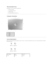
The placemat provides the number of the screws. Optional Module: (1 each) Modem: (1 each) Hard Drive: (2 each) Recommended Tools The procedures in this manual require the following tools: l #1 Phillips screwdriver l ¼-inch flat-blade screwdriver l Small plastic scribe l Flash BIOS update program floppy or CD Computer Orientation 1 back 2 right 3 front 4 left Screw Identification When you are removing and replacing components, print this section as a tool to lay out and keep track of screws and their sizes.
The placemat provides the number of the screws. Optional Module: (1 each) Modem: (1 each) Hard Drive: (2 each) Recommended Tools The procedures in this manual require the following tools: l #1 Phillips screwdriver l ¼-inch flat-blade screwdriver l Small plastic scribe l Flash BIOS update program floppy or CD Computer Orientation 1 back 2 right 3 front 4 left Screw Identification When you are removing and replacing components, print this section as a tool to lay out and keep track of screws and their sizes.

Service Manual
Page 24
... the hard drive out of the computer. even a slight bump can damage the drive. Use a standard #1 Phillips screwdriver to remove the two M3 x 3- Use spring tension to gently pry the carrier open near the connector at the back of the hard drive. Back to Contents Page Hard Drive Dell™ Latitude™ D810 Service Manual CAUTION: If you remove the hard drive from sources...
... the hard drive out of the computer. even a slight bump can damage the drive. Use a standard #1 Phillips screwdriver to remove the two M3 x 3- Use spring tension to gently pry the carrier open near the connector at the back of the hard drive. Back to Contents Page Hard Drive Dell™ Latitude™ D810 Service Manual CAUTION: If you remove the hard drive from sources...
Service Manual
Page 36
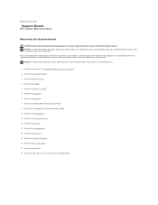
... provides a utility for transferring the Service Tag to Contents Page System Board Dell™ Latitude™ D810 Service Manual Removing the System Board CAUTION: Before performing the following procedures, read the safety instructions...Remove any installed batteries. 1. Remove the modem. 5. Remove the palm rest. 8. Remove the microprocessor fan. 12. Remove the microprocessor. 14. Remove the display assembly. 6. Remove the microprocessor thermal-cooling assembly. 10. Remove the PC Card carrier. 17. Remove the keyboard. 7. Remove the smart card reader. 16. Remove the hard drive. 15...
... provides a utility for transferring the Service Tag to Contents Page System Board Dell™ Latitude™ D810 Service Manual Removing the System Board CAUTION: Before performing the following procedures, read the safety instructions...Remove any installed batteries. 1. Remove the modem. 5. Remove the palm rest. 8. Remove the microprocessor fan. 12. Remove the microprocessor. 14. Remove the display assembly. 6. Remove the microprocessor thermal-cooling assembly. 10. Remove the PC Card carrier. 17. Remove the keyboard. 7. Remove the smart card reader. 16. Remove the hard drive. 15...
Service Manual
Page 39
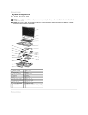
... not authorized by Dell is not covered by performing the removal procedure in reverse order. 1 display assembly 11 optical drive 2 display cable 12 battery 3 center control cover 13 computer base 4 keyboard 14 speakers 5 palm rest 15 hard drive 6 video-card assembly... 16 PCMIA card slot 7 video-card assembly fan 17 smart card reader 8 button board 18 microprocessor 9 system board support 19 microprocessor fan 10 system board 20 microprocessor thermal-cooling assembly Back to Contents Page System Components Dell™ Latitude™ D810...
... not authorized by Dell is not covered by performing the removal procedure in reverse order. 1 display assembly 11 optical drive 2 display cable 12 battery 3 center control cover 13 computer base 4 keyboard 14 speakers 5 palm rest 15 hard drive 6 video-card assembly... 16 PCMIA card slot 7 video-card assembly fan 17 smart card reader 8 button board 18 microprocessor 9 system board support 19 microprocessor fan 10 system board 20 microprocessor thermal-cooling assembly Back to Contents Page System Components Dell™ Latitude™ D810...
Service Manual
Page 40
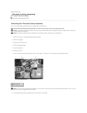
... palm rest. 7. Loosen in "Preparing to Contents Page Thermal-Cooling Assembly Dell™ Latitude™ D810 Service Manual Removing the Thermal-Cooling Assembly Removing the Thermal-Cooling Assembly There is one thermal-cooling assembly for the microprocessor, do not ...instructions in your Product Information Guide. Lift the thermal-cooling assembly straight up and remove it from electrical outlets, and remove any attached devices from the system board. Remove the keyboard. 6. Remove the hard drive. 3. The oils in your skin reduce the heat transfer capability of the ...
... palm rest. 7. Loosen in "Preparing to Contents Page Thermal-Cooling Assembly Dell™ Latitude™ D810 Service Manual Removing the Thermal-Cooling Assembly Removing the Thermal-Cooling Assembly There is one thermal-cooling assembly for the microprocessor, do not ...instructions in your Product Information Guide. Lift the thermal-cooling assembly straight up and remove it from electrical outlets, and remove any attached devices from the system board. Remove the keyboard. 6. Remove the hard drive. 3. The oils in your skin reduce the heat transfer capability of the ...


