Service Manual
Page 1
... subject to Contents Page Dell Inc. Dell™ Latitude™ D810 Service Manual Before You Begin System Components Memory Modules, Mini PCI Card, Modem, and Modules Internal Card With Bluetooth® Wireless Technology The Coin-Cell Battery Hard Drive Center Control Cover Display Assembly Keyboard Palm Rest Smart Card Reader PC Card Reader Speakers Microprocessor Thermal-Cooling Assembly Microprocessor Module Video Card Assembly Fans System Board Flashing the BIOS Pin Assignments...
... subject to Contents Page Dell Inc. Dell™ Latitude™ D810 Service Manual Before You Begin System Components Memory Modules, Mini PCI Card, Modem, and Modules Internal Card With Bluetooth® Wireless Technology The Coin-Cell Battery Hard Drive Center Control Cover Display Assembly Keyboard Palm Rest Smart Card Reader PC Card Reader Speakers Microprocessor Thermal-Cooling Assembly Microprocessor Module Video Card Assembly Fans System Board Flashing the BIOS Pin Assignments...
Service Manual
Page 2
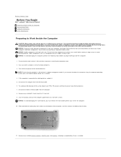
... the safety instructions that is not authorized by a certified service technician. Damage due to servicing that came with care. Back to Contents Page Before You Begin Dell™ Latitude™ D810 Service Manual Preparing to Work Inside the Computer Recommended Tools Computer Orientation Screw Identification Preparing to Work Inside the Computer CAUTION: Many repairs may only be done by Dell is connected to a docking...
... the safety instructions that is not authorized by a certified service technician. Damage due to servicing that came with care. Back to Contents Page Before You Begin Dell™ Latitude™ D810 Service Manual Preparing to Work Inside the Computer Recommended Tools Computer Orientation Screw Identification Preparing to Work Inside the Computer CAUTION: Many repairs may only be done by Dell is connected to a docking...

Service Manual
Page 6
... AC adapter is plugged in and that appear on the computer. Insert the flash BIOS update program floppy or CD and turn on the screen. The computer continues to Contents Page Flashing the BIOS Dell™ Latitude™ D810 Service Manual 1. When the update is installed properly. 2. Press , select Save changes and reboot, and then press to enter the system setup program. 4. Press during POST to save configuration changes...
... AC adapter is plugged in and that appear on the computer. Insert the flash BIOS update program floppy or CD and turn on the screen. The computer continues to Contents Page Flashing the BIOS Dell™ Latitude™ D810 Service Manual 1. When the update is installed properly. 2. Press , select Save changes and reboot, and then press to enter the system setup program. 4. Press during POST to save configuration changes...

Service Manual
Page 7
... Card With Bluetooth Wireless Technology 1. Remove the card from the connector cable. 7. Press the latch on the computer. Grasp the card and disconnect it from the computer. If you ordered an internal card with Bluetooth® wireless technology with your Product Information Guide. Follow the instructions in "Preparing to Contents Page Internal Card With Bluetooth® Wireless Technology Dell™ Latitude™ D810 Service Manual...
... Card With Bluetooth Wireless Technology 1. Remove the card from the connector cable. 7. Press the latch on the computer. Grasp the card and disconnect it from the computer. If you ordered an internal card with Bluetooth® wireless technology with your Product Information Guide. Follow the instructions in "Preparing to Contents Page Internal Card With Bluetooth® Wireless Technology Dell™ Latitude™ D810 Service Manual...
Service Manual
Page 9
... computer, use a plastic scribe or flat-blade screw driver to pry up and open it aside. Turn the computer top-side up the center control cover. 1 center control cover c. Remove the center control cover: a. Follow the instructions in your work surface. b. Lift the center control cover away from the computer, and lay it . 3. Back to Work Inside the Computer." 2. Back to Contents Page Center Control Cover Dell™ Latitude™ D810 Service Manual CAUTION: Before...
... computer, use a plastic scribe or flat-blade screw driver to pry up and open it aside. Turn the computer top-side up the center control cover. 1 center control cover c. Remove the center control cover: a. Follow the instructions in your work surface. b. Lift the center control cover away from the computer, and lay it . 3. Back to Work Inside the Computer." 2. Back to Contents Page Center Control Cover Dell™ Latitude™ D810 Service Manual CAUTION: Before...
Service Manual
Page 10
... and remove the main battery. 7. Connect the coin-cell battery connector to the manufacturer's instructions. however, without a battery; Discard used batteries according to the replacement battery. Turn off any attached devices and disconnect them off when you shut down the computer through the Start menu. 3. Disconnect the computer power cable from the electrical outlet for a few hours; Use your Product Information Guide. Disconnect...
... and remove the main battery. 7. Connect the coin-cell battery connector to the manufacturer's instructions. however, without a battery; Discard used batteries according to the replacement battery. Turn off any attached devices and disconnect them off when you shut down the computer through the Start menu. 3. Disconnect the computer power cable from the electrical outlet for a few hours; Use your Product Information Guide. Disconnect...

Service Manual
Page 12
... on the microprocessor thermal-cooling assembly. Back to Contents Page Microprocessor Module Dell™ Latitude™ D810 Service Manual Removing the Microprocessor Module CAUTION: Before performing the following procedures, read the safety instructions in your Product Information Guide. Follow the instructions in "Preparing to the microprocessor when turning the cam screw. 1. To loosen the ZIF socket, use a small, flat- Press and hold the screwdriver...
... on the microprocessor thermal-cooling assembly. Back to Contents Page Microprocessor Module Dell™ Latitude™ D810 Service Manual Removing the Microprocessor Module CAUTION: Before performing the following procedures, read the safety instructions in your Product Information Guide. Follow the instructions in "Preparing to the microprocessor when turning the cam screw. 1. To loosen the ZIF socket, use a small, flat- Press and hold the screwdriver...

Service Manual
Page 14
... Page Microprocessor Thermal-Cooling Assembly Dell™ Latitude™ D810 Service Manual Removing the Microprocessor Thermal-Cooling Assembly CAUTION: Before performing the following procedures, read the safety instructions in "Preparing to the system board. 1 captive screws (4) 2 microprocessor thermal- Follow the instructions in your Product Information Guide. NOTICE: Disconnect the computer and any installed batteries. 1. Loosen in consecutive order the four captive screws, labeled "1" through "4," that...
... Page Microprocessor Thermal-Cooling Assembly Dell™ Latitude™ D810 Service Manual Removing the Microprocessor Thermal-Cooling Assembly CAUTION: Before performing the following procedures, read the safety instructions in "Preparing to the system board. 1 captive screws (4) 2 microprocessor thermal- Follow the instructions in your Product Information Guide. NOTICE: Disconnect the computer and any installed batteries. 1. Loosen in consecutive order the four captive screws, labeled "1" through "4," that...
Service Manual
Page 16
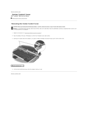
Follow the instructions in your work surface. 3. Back to Work Inside the Computer." 2. Starting on the computer. 1. Open the display all the way (180 degrees) so that it aside. Lift the center control cover away from the computer and lay it lies flat against your Product Information Guide. Back to Contents Page Center Control Cover Dell™ Latitude™ D810 Service Manual Removing the Center Control Cover Removing the Center Control Cover CAUTION: Before...
Follow the instructions in your work surface. 3. Back to Work Inside the Computer." 2. Starting on the computer. 1. Open the display all the way (180 degrees) so that it aside. Lift the center control cover away from the computer and lay it lies flat against your Product Information Guide. Back to Contents Page Center Control Cover Dell™ Latitude™ D810 Service Manual Removing the Center Control Cover Removing the Center Control Cover CAUTION: Before...
Service Manual
Page 17
... the computer. Follow the instructions in "Preparing to Contents Page Display Assembly Dell™ Latitude™ D810 Service Manual Display Assembly Display Bezel Display Panel Display Assembly CAUTION: Before performing the following procedures, read the safety instructions in your Product Information Guide. Turn over and remove the two M2.5 x 8-mm screws labeled "D" on the computer base, and then gently disconnect the connector. 7. Remove the antenna cable connector from the cable-routing guides. 6. NOTICE: To avoid electrostatic discharge...
... the computer. Follow the instructions in "Preparing to Contents Page Display Assembly Dell™ Latitude™ D810 Service Manual Display Assembly Display Bezel Display Panel Display Assembly CAUTION: Before performing the following procedures, read the safety instructions in your Product Information Guide. Turn over and remove the two M2.5 x 8-mm screws labeled "D" on the computer base, and then gently disconnect the connector. 7. Remove the antenna cable connector from the cable-routing guides. 6. NOTICE: To avoid electrostatic discharge...

Service Manual
Page 18
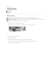
... discharge, ground yourself by using a wrist grounding strap or by lifting the inside edge of the bezel under the bumpers. 1 display 2 pull-tab 3 display cable connector 4 antenna cable 5 computer base 6 system board connector for display cable Display Bezel CAUTION: Before performing the following procedures, read the safety instructions in "Preparing to Work Inside the Computer." 2. Remove the display assembly. 3. NOTE: You may need to use a plastic scribe to the...
... discharge, ground yourself by using a wrist grounding strap or by lifting the inside edge of the bezel under the bumpers. 1 display 2 pull-tab 3 display cable connector 4 antenna cable 5 computer base 6 system board connector for display cable Display Bezel CAUTION: Before performing the following procedures, read the safety instructions in "Preparing to Work Inside the Computer." 2. Remove the display assembly. 3. NOTE: You may need to use a plastic scribe to the...
Service Manual
Page 21
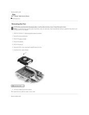
... Lift the fan straight up out of the fan. 7. Follow the instructions in your Product Information Guide. Remove the M2.5 x 5-mm screw from the top left corner of the computer. When replacing the fan, follow the steps in reverse order. Remove the display assembly. 4. Disconnect the fan cable connector. 1 M2.5 x 5-mm screw 8. Remove the center control cover. 3. Back to Work Inside the Computer." 2. Remove the keyboard. 5.
... Lift the fan straight up out of the fan. 7. Follow the instructions in your Product Information Guide. Remove the M2.5 x 5-mm screw from the top left corner of the computer. When replacing the fan, follow the steps in reverse order. Remove the display assembly. 4. Disconnect the fan cable connector. 1 M2.5 x 5-mm screw 8. Remove the center control cover. 3. Back to Work Inside the Computer." 2. Remove the keyboard. 5.

Service Manual
Page 24
... of the computer. mm screws. Follow the instructions in your Product Information Guide. Slide the hard drive out of the carrier. Removing the Hard Drive and Carrier 1. NOTE: Dell does not guarantee compatibility or provide support for hard drives from sources other than Dell. Back to Contents Page Hard Drive Dell™ Latitude™ D810 Service Manual CAUTION: If you remove the hard drive from...
... of the computer. mm screws. Follow the instructions in your Product Information Guide. Slide the hard drive out of the carrier. Removing the Hard Drive and Carrier 1. NOTE: Dell does not guarantee compatibility or provide support for hard drives from sources other than Dell. Back to Contents Page Hard Drive Dell™ Latitude™ D810 Service Manual CAUTION: If you remove the hard drive from...
Service Manual
Page 26
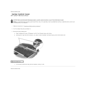
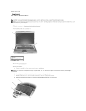
Remove the center control cover. 4. Remove the two M2.5 x 5-mm screws across the top of the computer to the keyboard connector. d. Back to Work Inside the Computer." 2. c. b. Turn the computer top-side up and open it toward the back of the keyboard. Remove the keyboard: a. Follow the instructions in "Preparing to Contents Page Keyboard Dell™ Latitude™ D810 Service Manual CAUTION: Before performing the following procedures...
Remove the center control cover. 4. Remove the two M2.5 x 5-mm screws across the top of the computer to the keyboard connector. d. Back to Work Inside the Computer." 2. c. b. Turn the computer top-side up and open it toward the back of the keyboard. Remove the keyboard: a. Follow the instructions in "Preparing to Contents Page Keyboard Dell™ Latitude™ D810 Service Manual CAUTION: Before performing the following procedures...

Service Manual
Page 33
... card reader 2 M2 x 3-mm screw 3 smart-card ZIF connector 6. Locate the smart card reader and disconnect the smart-card ZIF connector from under the tabs holding it in "Preparing to Contents Page Back to Work Inside the Computer." 2. Follow the instructions in place. Remove the single M2 x 3-mm screw in your Product Information Guide. Back to Contents Page Smart Card Reader Dell™ Latitude™ D810 Service Manual...
... card reader 2 M2 x 3-mm screw 3 smart-card ZIF connector 6. Locate the smart card reader and disconnect the smart-card ZIF connector from under the tabs holding it in "Preparing to Contents Page Back to Work Inside the Computer." 2. Follow the instructions in place. Remove the single M2 x 3-mm screw in your Product Information Guide. Back to Contents Page Smart Card Reader Dell™ Latitude™ D810 Service Manual...

Service Manual
Page 34
... screw 3 ZIF connector 7. Lift the smart card reader slightly and slide it in place. NOTICE: To avoid electrostatic discharge, ground yourself by using a wrist grounding strap or by periodically touching an unpainted metal surface (such as the back panel) on the computer. 1. Follow the instructions in your Product Information Guide. Back to Contents Page Smart Card Reader Dell™ Latitude™ D810 Service Manual Removing...
... screw 3 ZIF connector 7. Lift the smart card reader slightly and slide it in place. NOTICE: To avoid electrostatic discharge, ground yourself by using a wrist grounding strap or by periodically touching an unpainted metal surface (such as the back panel) on the computer. 1. Follow the instructions in your Product Information Guide. Back to Contents Page Smart Card Reader Dell™ Latitude™ D810 Service Manual Removing...
Service Manual
Page 39
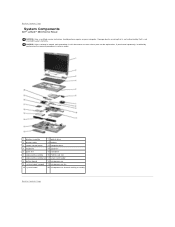
... drive 2 display cable 12 battery 3 center control cover 13 computer base 4 keyboard 14 speakers 5 palm rest 15 hard drive 6 video-card assembly 16 PCMIA card slot 7 video-card assembly fan 17 smart card reader 8 button board 18 microprocessor 9 system board support 19 microprocessor fan 10 system board 20 microprocessor thermal-cooling assembly Back to Contents Page Back to Contents Page System Components Dell™ Latitude™ D810 Service Manual NOTICE: Only a certified service technician should perform repairs on...
... drive 2 display cable 12 battery 3 center control cover 13 computer base 4 keyboard 14 speakers 5 palm rest 15 hard drive 6 video-card assembly 16 PCMIA card slot 7 video-card assembly fan 17 smart card reader 8 button board 18 microprocessor 9 system board support 19 microprocessor fan 10 system board 20 microprocessor thermal-cooling assembly Back to Contents Page Back to Contents Page System Components Dell™ Latitude™ D810 Service Manual NOTICE: Only a certified service technician should perform repairs on...

Service Manual
Page 44
... modules purchased from the connector. Replace the cover and screws. Turn on each end of the memory module connector until you touch any of your body before you feel the click, remove the module and reinstall it . Remove the center control cover. 3. Remove the module from Dell are replacing a memory module, remove the existing module. NOTICE: To prevent static damage to Work Inside the Computer." 2. 1 securing...
... modules purchased from the connector. Replace the cover and screws. Turn on each end of the memory module connector until you touch any of your body before you feel the click, remove the module and reinstall it . Remove the center control cover. 3. Remove the module from Dell are replacing a memory module, remove the existing module. NOTICE: To prevent static damage to Work Inside the Computer." 2. 1 securing...

Service Manual
Page 45
... the Start button, click Help and Support, and then click Computer Information. Insert the battery into the battery bay, or connect the AC adapter to components inside your computer, read the safety instructions in "Preparing to wait until you see the Windows desktop. The system configuration information remains the same. Then shut down until you feel the click, remove...
... the Start button, click Help and Support, and then click Computer Information. Insert the battery into the battery bay, or connect the AC adapter to components inside your computer, read the safety instructions in "Preparing to wait until you see the Windows desktop. The system configuration information remains the same. Then shut down until you feel the click, remove...

Service Manual
Page 47
.... Turn the computer over the connectors, remove the tubes. 5. Follow the instructions in your body before you are keyed to the system board, and set it aside. Replace the cover and tighten the screw. You can do so by their edges, and avoid touching pins and contacts. 1. NOTICE: The connectors are replacing a modem, remove the existing modem: a. NOTE: If the Mini PCI card's antenna cables...
.... Turn the computer over the connectors, remove the tubes. 5. Follow the instructions in your body before you are keyed to the system board, and set it aside. Replace the cover and tighten the screw. You can do so by their edges, and avoid touching pins and contacts. 1. NOTICE: The connectors are replacing a modem, remove the existing modem: a. NOTE: If the Mini PCI card's antenna cables...


