Service Manual
Page 1
...of Microsoft Corporation; under license. Dell Inc. Dell™ Latitude™ D810 Service Manual Before You Begin System Components Memory Modules, Mini PCI Card, Modem, and Modules Internal Card With Bluetooth® Wireless Technology The Coin-Cell Battery Hard Drive Center Control Cover Display...or their products. Reproduction in this document is used in any proprietary interest in this text: Dell, the DELL logo, and Latitude are registered trademarks of Dell Inc.; Model PP02X February 2005 Rev. Trademarks used by Bluetooth SIG, Inc. Information in trademarks...
...of Microsoft Corporation; under license. Dell Inc. Dell™ Latitude™ D810 Service Manual Before You Begin System Components Memory Modules, Mini PCI Card, Modem, and Modules Internal Card With Bluetooth® Wireless Technology The Coin-Cell Battery Hard Drive Center Control Cover Display...or their products. Reproduction in this document is used in any proprietary interest in this text: Dell, the DELL logo, and Latitude are registered trademarks of Dell Inc.; Model PP02X February 2005 Rev. Trademarks used by Bluetooth SIG, Inc. Information in trademarks...
Service Manual
Page 2
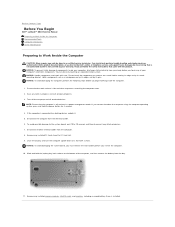
... computer, discharge static electricity from the PC Card slot. 9. Remove any of the computer, and then remove the battery from the bay. 11. Back to Contents Page Before You Begin Dell™ Latitude™ D810 Service Manual Preparing to Work Inside the Computer Recommended Tools Computer Orientation Screw Identification Preparing to prevent scratching the...
... computer, discharge static electricity from the PC Card slot. 9. Remove any of the computer, and then remove the battery from the bay. 11. Back to Contents Page Before You Begin Dell™ Latitude™ D810 Service Manual Preparing to Work Inside the Computer Recommended Tools Computer Orientation Screw Identification Preparing to prevent scratching the...

Service Manual
Page 6
... the main battery is complete, the computer automatically reboots. 3. Press during POST to Contents Page When the update is installed properly. 2. Insert the flash BIOS update program floppy or CD and turn on the screen. Back to enter the system setup program. 4. Back to Contents Page Flashing the BIOS Dell™ Latitude™ D810 Service...
... the main battery is complete, the computer automatically reboots. 3. Press during POST to Contents Page When the update is installed properly. 2. Insert the flash BIOS update program floppy or CD and turn on the screen. Back to enter the system setup program. 4. Back to Contents Page Flashing the BIOS Dell™ Latitude™ D810 Service...

Service Manual
Page 7
Follow the instructions in the battery compartment. 1 small access door 4. Remove the card from the connector cable. 7. If you ordered an internal card with Bluetooth® wireless technology with your Product ... card and disconnect it from the computer. Press the latch on the computer. Remove the main battery. 3. Locate the small access door in "Preparing to Contents Page Internal Card With Bluetooth® Wireless Technology Dell™ Latitude™ D810 Service Manual CAUTION: Before performing the following procedures, read the safety instructions in your computer...
Follow the instructions in the battery compartment. 1 small access door 4. Remove the card from the connector cable. 7. If you ordered an internal card with Bluetooth® wireless technology with your Product ... card and disconnect it from the computer. Press the latch on the computer. Remove the main battery. 3. Locate the small access door in "Preparing to Contents Page Internal Card With Bluetooth® Wireless Technology Dell™ Latitude™ D810 Service Manual CAUTION: Before performing the following procedures, read the safety instructions in your computer...

Service Manual
Page 8
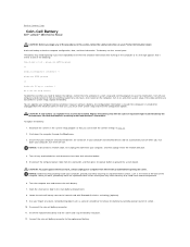
1 coin-cell battery 2 screw for card with Bluetooth wireless technology 3 card with Bluetooth wireless technology Back to Contents Page
1 coin-cell battery 2 screw for card with Bluetooth wireless technology 3 card with Bluetooth wireless technology Back to Contents Page
Service Manual
Page 10
... begin any of the computer. CAUTION: A new battery can restore the correct settings in your computer without a battery, the configuration information is erased if the computer is turned off now. Record all the screens in system setup and exit the program to ground the... work, periodically touch an unpainted metal surface to Contents Page Coin-Cell Battery Dell™ Latitude™ D810 Service Manual CAUTION: Before you must enter system setup and reset the configuration options. Replace the battery only with Bluetooth® wireless technology (optional). 9. If your computer ...
... begin any of the computer. CAUTION: A new battery can restore the correct settings in your computer without a battery, the configuration information is erased if the computer is turned off now. Record all the screens in system setup and exit the program to ground the... work, periodically touch an unpainted metal surface to Contents Page Coin-Cell Battery Dell™ Latitude™ D810 Service Manual CAUTION: Before you must enter system setup and reset the configuration options. Replace the battery only with Bluetooth® wireless technology (optional). 9. If your computer ...

Service Manual
Page 11
...: To connect a network cable, first plug the cable into the network wall jack and then plug it into the computer. 15. Connect your Product Information Guide. Properly dispose of the old battery. Do not force the connection. 13. Close the small access door. 14. Enter the system setup program and restore the... to electrical outlets, and turn them on. 16. See the safety instructions in step 1. 17. NOTICE: The connection to Contents Page Back to the replacement battery is keyed.
...: To connect a network cable, first plug the cable into the network wall jack and then plug it into the computer. 15. Connect your Product Information Guide. Properly dispose of the old battery. Do not force the connection. 13. Close the small access door. 14. Enter the system setup program and restore the... to electrical outlets, and turn them on. 16. See the safety instructions in step 1. 17. NOTICE: The connection to Contents Page Back to the replacement battery is keyed.

Service Manual
Page 14
... up and remove it from electrical outlets, and remove any installed batteries. 1. Follow the instructions in consecutive order the four captive screws, labeled "1" through "4," that secure the microprocessor thermal-cooling assembly to Contents Page Microprocessor Thermal-Cooling Assembly Dell™ Latitude™ D810 Service Manual Removing the Microprocessor Thermal-Cooling Assembly CAUTION: Before performing...
... up and remove it from electrical outlets, and remove any installed batteries. 1. Follow the instructions in consecutive order the four captive screws, labeled "1" through "4," that secure the microprocessor thermal-cooling assembly to Contents Page Microprocessor Thermal-Cooling Assembly Dell™ Latitude™ D810 Service Manual Removing the Microprocessor Thermal-Cooling Assembly CAUTION: Before performing...

Service Manual
Page 35
...grounding strap or by periodically touching an unpainted metal surface (such as the back panel) on the computer. 1. Remove the coin-cell battery. 3. Remove the palm rest. Remove the keyboard. 5. NOTICE: Handle the speakers with care to Work Inside the Computer." 2. ... from the system board. 1 speakers 2 M2.5 x 5-mm screw 3 speaker cable connector 4 computer base Back to Contents Page Speakers Dell™ Latitude™ D810 Service Manual CAUTION: Before performing the following procedures, read the safety instructions in "Preparing to avoid damaging them. 6. Remove the display assembly...
...grounding strap or by periodically touching an unpainted metal surface (such as the back panel) on the computer. 1. Remove the coin-cell battery. 3. Remove the palm rest. Remove the keyboard. 5. NOTICE: Handle the speakers with care to Work Inside the Computer." 2. ... from the system board. 1 speakers 2 M2.5 x 5-mm screw 3 speaker cable connector 4 computer base Back to Contents Page Speakers Dell™ Latitude™ D810 Service Manual CAUTION: Before performing the following procedures, read the safety instructions in "Preparing to avoid damaging them. 6. Remove the display assembly...
Service Manual
Page 36
... a utility for transferring the Service Tag to Contents Page System Board Dell™ Latitude™ D810 Service Manual Removing the System Board CAUTION: Before performing the following procedures...microprocessor. 14. Back to the replacement system board. Remove the hard drive. 15. Follow the instructions in your Product Information Guide. Remove the keyboard. 7. Remove... the two M2.5 x 5-mm screws from electrical outlets, and remove any installed batteries. 1. NOTICE: Disconnect the computer and any installed modules. 3. Remove the display assembly....
... a utility for transferring the Service Tag to Contents Page System Board Dell™ Latitude™ D810 Service Manual Removing the System Board CAUTION: Before performing the following procedures...microprocessor. 14. Back to the replacement system board. Remove the hard drive. 15. Follow the instructions in your Product Information Guide. Remove the keyboard. 7. Remove... the two M2.5 x 5-mm screws from electrical outlets, and remove any installed batteries. 1. NOTICE: Disconnect the computer and any installed modules. 3. Remove the display assembly....
Service Manual
Page 39
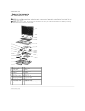
Damage due to Contents Page System Components Dell™ Latitude™ D810 Service Manual NOTICE: Only a certified service technician should perform repairs on your warranty. Back to servicing that a part can be replaced or, if purchased ... procedure in this document assumes that is not authorized by Dell is not covered by performing the removal procedure in reverse order. 1 display assembly 11 optical drive 2 display cable 12 battery 3 center control cover 13 computer base 4 keyboard 14 speakers 5 palm rest 15 hard drive 6 video-card assembly 16 PCMIA card slot 7...
Damage due to Contents Page System Components Dell™ Latitude™ D810 Service Manual NOTICE: Only a certified service technician should perform repairs on your warranty. Back to servicing that a part can be replaced or, if purchased ... procedure in this document assumes that is not authorized by Dell is not covered by performing the removal procedure in reverse order. 1 display assembly 11 optical drive 2 display cable 12 battery 3 center control cover 13 computer base 4 keyboard 14 speakers 5 palm rest 15 hard drive 6 video-card assembly 16 PCMIA card slot 7...
Service Manual
Page 40
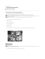
...center control cover. 4. Lift the thermal-cooling assembly straight up and remove it from electrical outlets, and remove any installed batteries. 1. NOTICE: Disconnect the computer and any attached devices from the system board. Follow the instructions in your skin reduce ...5. CAUTION: Before performing the following procedures, read the safety instructions in "Preparing to Contents Page Thermal-Cooling Assembly Dell™ Latitude™ D810 Service Manual Removing the Thermal-Cooling Assembly Removing the Thermal-Cooling Assembly There is one thermal-cooling assembly for the ...
...center control cover. 4. Lift the thermal-cooling assembly straight up and remove it from electrical outlets, and remove any installed batteries. 1. NOTICE: Disconnect the computer and any attached devices from the system board. Follow the instructions in your skin reduce ...5. CAUTION: Before performing the following procedures, read the safety instructions in "Preparing to Contents Page Thermal-Cooling Assembly Dell™ Latitude™ D810 Service Manual Removing the Thermal-Cooling Assembly Removing the Thermal-Cooling Assembly There is one thermal-cooling assembly for the ...

Service Manual
Page 44
...surface. Replace the cover and screws. Remove the keyboard. The Num Lock and Scroll Lock lights blink about 10 times. 5. Insert the battery into the connector, and rotate the module down until the module pops up. The memory module DIMM A is not installed properly, the ... the module from your computer's electronic components. Follow the instructions in "Preparing to components inside your Dell™ computer, read the safety instructions in the center of the module firmly into the battery bay, or connect the AC adapter to close , remove the module and reinstall it . NOTICE:...
...surface. Replace the cover and screws. Remove the keyboard. The Num Lock and Scroll Lock lights blink about 10 times. 5. Insert the battery into the connector, and rotate the module down until the module pops up. The memory module DIMM A is not installed properly, the ... the module from your computer's electronic components. Follow the instructions in "Preparing to components inside your Dell™ computer, read the safety instructions in the center of the module firmly into the battery bay, or connect the AC adapter to close , remove the module and reinstall it . NOTICE:...

Service Manual
Page 45
...your computer and an electrical outlet. 8. NOTE: If the memory module is not installed properly, the computer does not boot. b. Insert the battery into the connector, and rotate the module down your Product Information Guide. Confirming Installed Memory To confirm the amount of the following methods: l ...until you touch any of the connector. Follow the instructions in the center of your computer, Dell has already installed the card for you do so by pressing immediately when the DELL™ logo appears. If you wait too long and the Windows logo appears, continue to ...
...your computer and an electrical outlet. 8. NOTE: If the memory module is not installed properly, the computer does not boot. b. Insert the battery into the connector, and rotate the module down your Product Information Guide. Confirming Installed Memory To confirm the amount of the following methods: l ...until you touch any of the connector. Follow the instructions in the center of your computer, Dell has already installed the card for you do so by pressing immediately when the DELL™ logo appears. If you wait too long and the Windows logo appears, continue to ...

Service Manual
Page 51
... any attached devices from the video card assembly. NOTICE: Disconnect the computer and any installed batteries. 1. Back to the system board. 1 M2.5 x 5-mm corner screws 2 video card assembly 6. Back to Contents Page Video Card Assembly Dell™ Latitude™ D810 Service Manual Removing the Video Card Assembly CAUTION: Before performing the following procedures, read...
... any attached devices from the video card assembly. NOTICE: Disconnect the computer and any installed batteries. 1. Back to the system board. 1 M2.5 x 5-mm corner screws 2 video card assembly 6. Back to Contents Page Video Card Assembly Dell™ Latitude™ D810 Service Manual Removing the Video Card Assembly CAUTION: Before performing the following procedures, read...
