Service Manual
Page 1
...trade names other than its own. Bluetooth is strictly forbidden. is a trademark owned by Dell Inc. Microsoft and Windows are trademarks of Microsoft Corporation; Dell™ Latitude™ D810 Service Manual Before You Begin System Components Memory Modules, Mini PCI Card, Modem, and...Smart Card Reader PC Card Reader Speakers Microprocessor Thermal-Cooling Assembly Microprocessor Module Video Card Assembly Fans System Board Flashing the BIOS Pin Assignments for property damage, personal injury, or death. All rights reserved. NOTICE: A NOTICE indicates either the ...
...trade names other than its own. Bluetooth is strictly forbidden. is a trademark owned by Dell Inc. Microsoft and Windows are trademarks of Microsoft Corporation; Dell™ Latitude™ D810 Service Manual Before You Begin System Components Memory Modules, Mini PCI Card, Modem, and...Smart Card Reader PC Card Reader Speakers Microprocessor Thermal-Cooling Assembly Microprocessor Module Video Card Assembly Fans System Board Flashing the BIOS Pin Assignments for property damage, personal injury, or death. All rights reserved. NOTICE: A NOTICE indicates either the ...
Service Manual
Page 3
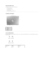
Recommended Tools The procedures in this manual require the following tools: l #1 Phillips screwdriver l ¼-inch flat-blade screwdriver l Small plastic scribe l Flash BIOS update program floppy or CD Computer Orientation 1 back 2 right 3 front 4 left Screw Identification When you are removing and replacing components, print this section as a tool to lay out and keep track of screws and their sizes. The placemat provides the number of the screws. Optional Module: (1 each) Modem: (1 each) Hard Drive: (2 each)
Recommended Tools The procedures in this manual require the following tools: l #1 Phillips screwdriver l ¼-inch flat-blade screwdriver l Small plastic scribe l Flash BIOS update program floppy or CD Computer Orientation 1 back 2 right 3 front 4 left Screw Identification When you are removing and replacing components, print this section as a tool to lay out and keep track of screws and their sizes. The placemat provides the number of the screws. Optional Module: (1 each) Modem: (1 each) Hard Drive: (2 each)

Service Manual
Page 6
... BIOS Dell™ Latitude™ D810 Service Manual 1. Back to boot and updates the new BIOS. When the update is plugged in and that appear on the computer. Remove the flash BIOS update program floppy or CD from the drive and restart the computer. Insert the flash BIOS update program floppy or CD and turn on the screen...
... BIOS Dell™ Latitude™ D810 Service Manual 1. Back to boot and updates the new BIOS. When the update is plugged in and that appear on the computer. Remove the flash BIOS update program floppy or CD from the drive and restart the computer. Insert the flash BIOS update program floppy or CD and turn on the screen...

Service Manual
Page 13
...the microprocessor module has a triangle that aligns with the pin-1 corner of the microprocessor module with the triangle on how to flash the BIOS, see "Flashing the BIOS." When the microprocessor module is correctly seated, all four corners are higher than the others, the module is not seated correctly. 2. ... NOTICE: Ensure that the cam lock is in the ZIF socket to avoid permanent damage to the module and the socket. Update the BIOS using a flash BIOS update program floppy or CD. For instructions on the pin-1 corner of the module are aligned at the same height. If one or...
...the microprocessor module has a triangle that aligns with the pin-1 corner of the microprocessor module with the triangle on how to flash the BIOS, see "Flashing the BIOS." When the microprocessor module is correctly seated, all four corners are higher than the others, the module is not seated correctly. 2. ... NOTICE: Ensure that the cam lock is in the ZIF socket to avoid permanent damage to the module and the socket. Update the BIOS using a flash BIOS update program floppy or CD. For instructions on the pin-1 corner of the module are aligned at the same height. If one or...
Service Manual
Page 36
Back to Contents Page System Board Dell™ Latitude™ D810 Service Manual Removing the System Board CAUTION: Before performing the following procedures, read the safety instructions in "Preparing to the replacement system board. NOTICE: ...microprocessor. 14. Remove the smart card reader. 16. Remove the microprocessor thermal-cooling assembly. 10. Remove the hard drive. 15. Follow the instructions in your Product Information Guide. The system board's BIOS chip contains the Service Tag, which is also visible on a barcode label on the computer. Remove the speakers. 18. ...
Back to Contents Page System Board Dell™ Latitude™ D810 Service Manual Removing the System Board CAUTION: Before performing the following procedures, read the safety instructions in "Preparing to the replacement system board. NOTICE: ...microprocessor. 14. Remove the smart card reader. 16. Remove the microprocessor thermal-cooling assembly. 10. Remove the hard drive. 15. Follow the instructions in your Product Information Guide. The system board's BIOS chip contains the Service Tag, which is also visible on a barcode label on the computer. Remove the speakers. 18. ...

Service Manual
Page 38
... and ensure that no stray screws remain inside the computer. Back to Contents Page Failure to do so may need to press outward on the screen. Insert the floppy or CD that appear on the base near the audio connectors to provide enough clearance for the audio connectors. Installing the System.... After the connectors are dislodged, lift the board out of the replacement system board. 3. Follow the instructions that accompanied the replacement system board into the BIOS of the base. NOTE: You may result in reverse order. c.
... and ensure that no stray screws remain inside the computer. Back to Contents Page Failure to do so may need to press outward on the screen. Insert the floppy or CD that appear on the base near the audio connectors to provide enough clearance for the audio connectors. Installing the System.... After the connectors are dislodged, lift the board out of the replacement system board. 3. Follow the instructions that accompanied the replacement system board into the BIOS of the base. NOTE: You may result in reverse order. c.