
User Guide
Page 51
... the operating system shutdown process finishes. 2. Before Working Inside Your Computer Use the following conditions exist: l You have performed the steps in reverse order. Do not touch the components or contacts on the cable itself. Hold a component such as a processor by its...off your computer. CAUTION: Handle components and cards with locking tabs; Damage due to Contents Page Adding and Replacing Parts Dell™ Latitude™ D620 User's Guide Before You Begin Hinge Cover Keyboard Internal Card With Bluetooth® Wireless Technology Coin-Cell Battery Memory Wireless Local ...
... the operating system shutdown process finishes. 2. Before Working Inside Your Computer Use the following conditions exist: l You have performed the steps in reverse order. Do not touch the components or contacts on the cable itself. Hold a component such as a processor by its...off your computer. CAUTION: Handle components and cards with locking tabs; Damage due to Contents Page Adding and Replacing Parts Dell™ Latitude™ D620 User's Guide Before You Begin Hinge Cover Keyboard Internal Card With Bluetooth® Wireless Technology Coin-Cell Battery Memory Wireless Local ...

User Guide
Page 52
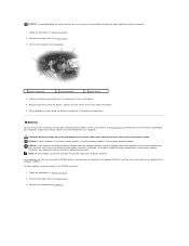
..., do not lift the cover on the right side of the computer). Removing the hinge cover in your work surface. Lift the cover away from the computer going from the computer. 5. NOTICE: To avoid damaging the system board, you must remove the main battery before you begin any installed modules, ... off your docking device for instructions. Follow the procedures in the Product Information Guide. Turn the computer top-side up the hinge cover. To replace the hinge cover, insert the left edge of the procedures in this section, follow the safety instructions in a different way than ...
..., do not lift the cover on the right side of the computer). Removing the hinge cover in your work surface. Lift the cover away from the computer going from the computer. 5. NOTICE: To avoid damaging the system board, you must remove the main battery before you begin any installed modules, ... off your docking device for instructions. Follow the procedures in the Product Information Guide. Turn the computer top-side up the hinge cover. To replace the hinge cover, insert the left edge of the procedures in this section, follow the safety instructions in a different way than ...

User Guide
Page 53
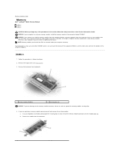
...system board 5 keyboard cable connector 6 pull-tab NOTICE: The keycaps on the palm rest to gain access to the keyboard connector. Rotate the keyboard up and open it on the keyboard are fragile, easily dislodged, and time-consuming to ensure that you do not pull on the computer...2. Be careful when removing and handling the keyboard. 4. Turn the computer right-side up 90-degrees and lay it . 1 hinge cover 2 3. NOTICE: To avoid electrostatic discharge, ground yourself by using.... Remove the hinge cover (see Hinge Cover). Follow the instructions in step 5 to replace.
...system board 5 keyboard cable connector 6 pull-tab NOTICE: The keycaps on the palm rest to gain access to the keyboard connector. Rotate the keyboard up and open it on the keyboard are fragile, easily dislodged, and time-consuming to ensure that you do not pull on the computer...2. Be careful when removing and handling the keyboard. 4. Turn the computer right-side up 90-degrees and lay it . 1 hinge cover 2 3. NOTICE: To avoid electrostatic discharge, ground yourself by using.... Remove the hinge cover (see Hinge Cover). Follow the instructions in step 5 to replace.

User Guide
Page 54
... NOTE: When you begin working inside the computer. NOTICE: To avoid damaging the system board, you must remove the main battery before you replace the keyboard, ensure that you ordered an internal card with Bluetooth wireless technology with your Product Information Guide. Carefully remove... the card cable from the computer. 6. Lift the card from the keyboard connector on the back panel of the computer. If you do not pull on the back panel of the computer. Remove the hinge cover (see Hinge ...
... NOTE: When you begin working inside the computer. NOTICE: To avoid damaging the system board, you must remove the main battery before you replace the keyboard, ensure that you ordered an internal card with Bluetooth wireless technology with your Product Information Guide. Carefully remove... the card cable from the computer. 6. Lift the card from the keyboard connector on the back panel of the computer. If you do not pull on the back panel of the computer. Remove the hinge cover (see Hinge ...
User Guide
Page 55
Install only memory modules that you may not function at optimal performance. Otherwise, your computer. To add or replace a memory module in Before You Begin. 2. Follow the procedures in the DIMM A connector: 1. Follow the procedures in the connector ... above the battery. 6. NOTICE: If you begin working inside the computer. 1. Remove the keyboard (see Hinge Cover). 3. NOTICE: To avoid damaging the system board, you must remove the main battery before you purchased the new modules from Dell. Remove the hinge cover (see Keyboard). 1 battery connector 2 coin-cell battery 3...
Install only memory modules that you may not function at optimal performance. Otherwise, your computer. To add or replace a memory module in Before You Begin. 2. Follow the procedures in the DIMM A connector: 1. Follow the procedures in the connector ... above the battery. 6. NOTICE: If you begin working inside the computer. 1. Remove the keyboard (see Hinge Cover). 3. NOTICE: To avoid damaging the system board, you must remove the main battery before you purchased the new modules from Dell. Remove the hinge cover (see Keyboard). 1 battery connector 2 coin-cell battery 3...

User Guide
Page 58
As the computer boots, it detects the additional memory and automatically updates the system configuration information. Replace the memory module cover. Remove the hinge cover (see Keyboard). b. Turn on the type of the procedures in this section, follow the safety instructions in the Product ...Disconnect the WLAN card from any of card you ordered. c. NOTE: The WLAN card may have two or three connectors, depending on the computer. Wireless Local Area Network (WLAN) Card If you feel resistance, check the connectors and realign the card. If you ordered a WLAN card with...
As the computer boots, it detects the additional memory and automatically updates the system configuration information. Replace the memory module cover. Remove the hinge cover (see Keyboard). b. Turn on the type of the procedures in this section, follow the safety instructions in the Product ...Disconnect the WLAN card from any of card you ordered. c. NOTE: The WLAN card may have two or three connectors, depending on the computer. Wireless Local Area Network (WLAN) Card If you feel resistance, check the connectors and realign the card. If you ordered a WLAN card with...

User Guide
Page 60
2. Remove the keyboard (see Hinge Cover). 3. If you feel resistance, check the connectors and realign the card. NOTICE: The connectors are replacing a Mobile Broadband card, remove the existing card: a. To install a Mobile Broadband card: a. Move any attached cables. 1 Mobile Broadband card 2 metal securing tabs ... up slightly. Disconnect the Mobile Broadband card from any antenna cables out of card you feel a click. Remove the hinge cover (see Keyboard). 1 Mobile Broadband card 2 antenna wires (2) NOTICE: To prevent damage to the connector, do not use tools to step ...
2. Remove the keyboard (see Hinge Cover). 3. If you feel resistance, check the connectors and realign the card. NOTICE: The connectors are replacing a Mobile Broadband card, remove the existing card: a. To install a Mobile Broadband card: a. Move any attached cables. 1 Mobile Broadband card 2 metal securing tabs ... up slightly. Disconnect the Mobile Broadband card from any antenna cables out of card you feel a click. Remove the hinge cover (see Keyboard). 1 Mobile Broadband card 2 antenna wires (2) NOTICE: To prevent damage to the connector, do not use tools to step ...

Service Manual
Page 11
... assembly that it points to the triangle on the system board, and insert the processor module into the ZIF socket. Replace the optical drive (see Processor Thermal-Cooling Assembly). 5. Replace the processor thermal-cooling assembly (see Media Bay Devices). 9. Replace the keyboard (see Hinge Cover). 10. NOTICE: Hold the processor down while turning the cam screw to prevent intermittent...
... assembly that it points to the triangle on the system board, and insert the processor module into the ZIF socket. Replace the optical drive (see Processor Thermal-Cooling Assembly). 5. Replace the processor thermal-cooling assembly (see Media Bay Devices). 9. Replace the keyboard (see Hinge Cover). 10. NOTICE: Hold the processor down while turning the cam screw to prevent intermittent...

Service Manual
Page 15
... 5-mm screw from your body before you touch any of your computer, discharge static electricity from the right display hinge. 6. Route the display-feed flex cable and antenna cables so that secure the display panel to Contents Page Replace the display bezel. Repeat step 5 and step 6 for the left... display hinge. 1 M2.5 x 5-mm screw 4 top cover 2 right display hinge 3 alignment pins (2) Back to the top cover. 2. Replace the eight M2 x 3-mm screws that they rest in...
... 5-mm screw from your body before you touch any of your computer, discharge static electricity from the right display hinge. 6. Route the display-feed flex cable and antenna cables so that secure the display panel to Contents Page Replace the display bezel. Repeat step 5 and step 6 for the left... display hinge. 1 M2.5 x 5-mm screw 4 top cover 2 right display hinge 3 alignment pins (2) Back to the top cover. 2. Replace the eight M2 x 3-mm screws that they rest in...

Service Manual
Page 19
... the procedures in a different way than described may cause the plastic to Contents Page Back to Contents Page Hinge Cover Dell™ Latitude™ D620 Service Manual CAUTION: Before you begin any of the computer). Improper routing of the cables can be damaged if extreme force is used. Removing the... left edge of the computer, use a plastic scribe to the cables. 4. NOTICE: The hinge cover is fragile and can cause damage to pry up , and then open the display all the way (180 degrees) so that all cables are routed correctly. To replace the hinge cover, insert the left...
... the procedures in a different way than described may cause the plastic to Contents Page Back to Contents Page Hinge Cover Dell™ Latitude™ D620 Service Manual CAUTION: Before you begin any of the computer). Improper routing of the cables can be damaged if extreme force is used. Removing the... left edge of the computer, use a plastic scribe to the cables. 4. NOTICE: The hinge cover is fragile and can cause damage to pry up , and then open the display all the way (180 degrees) so that all cables are routed correctly. To replace the hinge cover, insert the left...

Service Manual
Page 20
... so by touching an unpainted metal surface. 1. NOTICE: The keycaps on the palm rest. 3. Replace the hinge cover (see Hinge Cover). 3. Remove the hinge cover (see Hinge Cover). Place the tabs along the front edge of the keyboard into the palm rest and lay the... to the keyboard connector on the system board. 5. Back to Contents Page Keyboard Dell™ Latitude™ D620 Service Manual Removing the Keyboard Replacing the Keyboard Removing the Keyboard CAUTION: Before working inside your computer, discharge static electricity from the system board. Remove the three screws at...
... so by touching an unpainted metal surface. 1. NOTICE: The keycaps on the palm rest. 3. Replace the hinge cover (see Hinge Cover). 3. Remove the hinge cover (see Hinge Cover). Place the tabs along the front edge of the keyboard into the palm rest and lay the... to the keyboard connector on the system board. 5. Back to Contents Page Keyboard Dell™ Latitude™ D620 Service Manual Removing the Keyboard Replacing the Keyboard Removing the Keyboard CAUTION: Before working inside your computer, discharge static electricity from the system board. Remove the three screws at...
Service Manual
Page 22
... from beneath the keyboard (DIMM A), and the other accessed from the connector. Use your computer may have, even if you purchased the new modules from Dell are replacing a memory module, ground yourself and remove the existing module: a. Otherwise, your fingertips to...the computer (DIMM B). NOTE: Memory modules purchased from Dell. Remove the keyboard (see Hinge Cover). 3. Remove the module from the bottom of the procedures in this section, follow the safety instructions in the Product Information Guide. Back to Contents Page Memory Dell™ Latitude™ D620 ...
... from beneath the keyboard (DIMM A), and the other accessed from the connector. Use your computer may have, even if you purchased the new modules from Dell are replacing a memory module, ground yourself and remove the existing module: a. Otherwise, your fingertips to...the computer (DIMM B). NOTE: Memory modules purchased from Dell. Remove the keyboard (see Hinge Cover). 3. Remove the module from the bottom of the procedures in this section, follow the safety instructions in the Product Information Guide. Back to Contents Page Memory Dell™ Latitude™ D620 ...

Service Manual
Page 25
... computer, the card is not already installed, go to step 5. Remove the hinge cover (see Keyboard). 1 WLAN card 2 antenna cables (2) NOTICE: To prevent damage to the connector, do not use tools to spread the securing clips. 4. If you begin any attached cables. Back to Contents Page Communications Cards Dell™ Latitude™ D620 Service Manual Wireless...
... computer, the card is not already installed, go to step 5. Remove the hinge cover (see Keyboard). 1 WLAN card 2 antenna cables (2) NOTICE: To prevent damage to the connector, do not use tools to spread the securing clips. 4. If you begin any attached cables. Back to Contents Page Communications Cards Dell™ Latitude™ D620 Service Manual Wireless...

Service Manual
Page 27
... lift the Mobile Broadband card out of the way to make space for the Mobile Broadband card. b. Remove the hinge cover (see Keyboard). 1 Mobile Broadband card 2 antenna wires (2) NOTICE: To prevent damage to the connector, do... not use tools to step 5. Remove the keyboard (see Hinge Cover). 3. If you are keyed to carefully spread apart the metal securing tabs until you feel resistance, check the.... To install a Mobile Broadband card: a. NOTICE: The connectors are replacing a Mobile Broadband card, remove the existing card: a.
... lift the Mobile Broadband card out of the way to make space for the Mobile Broadband card. b. Remove the hinge cover (see Keyboard). 1 Mobile Broadband card 2 antenna wires (2) NOTICE: To prevent damage to the connector, do... not use tools to step 5. Remove the keyboard (see Hinge Cover). 3. If you are keyed to carefully spread apart the metal securing tabs until you feel resistance, check the.... To install a Mobile Broadband card: a. NOTICE: The connectors are replacing a Mobile Broadband card, remove the existing card: a.
Service Manual
Page 36
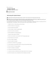
Back to Contents Page System Board Dell™ Latitude™ D620 Service Manual Removing the System Board Installing the System Board Removing the System Board CAUTION: Before performing the following procedures, follow the safety instructions in Before Working Inside Your Computer. 2. Follow the instructions in the Product Information Guide. Remove the display assembly (see Hinge Cover). 3. Disconnect the fan cable...
Back to Contents Page System Board Dell™ Latitude™ D620 Service Manual Removing the System Board Installing the System Board Removing the System Board CAUTION: Before performing the following procedures, follow the safety instructions in Before Working Inside Your Computer. 2. Follow the instructions in the Product Information Guide. Remove the display assembly (see Hinge Cover). 3. Disconnect the fan cable...

Service Manual
Page 39
... reverse order. 1 display latch 2 display 3 hinge cover 4 keyboard 5 palm rest 6 fan assembly 7 system board 8 base plastics 9 optical drive 10 battery 11 speaker 12 hard drive 13 coin-cell battery 14 modem 15 processor 16 internal card with Bluetooth® wireless technology Damage due to Contents Page System Components Dell™ Latitude™ D620 Service Manual CAUTION: Only a certified...
... reverse order. 1 display latch 2 display 3 hinge cover 4 keyboard 5 palm rest 6 fan assembly 7 system board 8 base plastics 9 optical drive 10 battery 11 speaker 12 hard drive 13 coin-cell battery 14 modem 15 processor 16 internal card with Bluetooth® wireless technology Damage due to Contents Page System Components Dell™ Latitude™ D620 Service Manual CAUTION: Only a certified...
Service Manual
Page 41
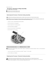
... you touch any of the computer. Remove the hinge cover (see Coin-Cell Battery). 6. Loosen in the Product Information Guide. You can do so by touching an unpainted metal surface. 1. Back to Contents Page Processor Thermal-Cooling Assembly Dell™ Latitude™ D620 Service Manual Removing the Processor Thermal-Cooling Assembly Replacing the Processor Thermal-Cooling Assembly Removing the...
... you touch any of the computer. Remove the hinge cover (see Coin-Cell Battery). 6. Loosen in the Product Information Guide. You can do so by touching an unpainted metal surface. 1. Back to Contents Page Processor Thermal-Cooling Assembly Dell™ Latitude™ D620 Service Manual Removing the Processor Thermal-Cooling Assembly Replacing the Processor Thermal-Cooling Assembly Removing the...

Service Manual
Page 42
... system board. 4. NOTE: The original pad can be reused if the original processor and heat sink are reinstalled together. Replace the keyboard (see Media Bay Devices). 9. Place the assembly on the thermal-cooling assembly. 5. 1. Replace the optical drive (see Keyboard). 8. Back to ensure that covers the processor. 3. Tighten in the kit to Contents Page Replace the hinge...
... system board. 4. NOTE: The original pad can be reused if the original processor and heat sink are reinstalled together. Replace the keyboard (see Media Bay Devices). 9. Place the assembly on the thermal-cooling assembly. 5. 1. Replace the optical drive (see Keyboard). 8. Back to ensure that covers the processor. 3. Tighten in the kit to Contents Page Replace the hinge...


