

Dell Monitor Outline Dimensions
Page 1
D2215H Outline Dimension Z = 0 100.0, (4X) (3.94) Unit : mm (inch) Dimension : Nominal Drawing : Not to scale M4x10 (4X) 50.4 (1.98) 13.5 (0.53) 516.4 (20.33) 478.0 (18.82) 13.9, 2X (0.55) Back view of Monitor without stand Tilt 19.3 (0.76) 320.4 (12.61) 269.5 (10.61) 374.5 (14.74) 355.3 (13.99) 54.2 (2.13) 14.5 (0.57) 124.7 (4.91) 143.6 (5.65) 1.0 (0.04) 85.8 (3.38) 31.7 (1.25) 182.2 (7.17) 51 (2.01) 165.9 (6.53)
D2215H Outline Dimension Z = 0 100.0, (4X) (3.94) Unit : mm (inch) Dimension : Nominal Drawing : Not to scale M4x10 (4X) 50.4 (1.98) 13.5 (0.53) 516.4 (20.33) 478.0 (18.82) 13.9, 2X (0.55) Back view of Monitor without stand Tilt 19.3 (0.76) 320.4 (12.61) 269.5 (10.61) 374.5 (14.74) 355.3 (13.99) 54.2 (2.13) 14.5 (0.57) 124.7 (4.91) 143.6 (5.65) 1.0 (0.04) 85.8 (3.38) 31.7 (1.25) 182.2 (7.17) 51 (2.01) 165.9 (6.53)

Dell Monitor Outline Dimensions
Page 2
D2215H& Outline Dimension 100.0, (4x) (3.94) Unit : mm (inch) Dimension : Nominal Drawing : Not to scale 50.4 (1.98) 13.5 (0.53) 407.6(16.05) 510.2 (20.09) 527.4 (20.76) 347.2 (13.67) 189.9(7.48) 130.0 (5.12) 380.2 (14.97) 31.2 (1.23) 22.2 (0.87) 217.2(8.55) 374.0(14.72) 605.4 (23.83) 320.4 (12.61) 288.7 (11.37) 31.7 (0.1.25) 95.2 (3.75) 19.2(0.76) 88.9 (3.50) 516.4 (20.33) 478.0 (18.82) 19.2 (0.76) 13.7 (0.54) Z = 0 13.5 (0.53) Lift Pivot 90° M4x10 (4x) Tilt 244.5 (9.63) 52.1 (2.05) 220.2 (8.67) 244.5 (9.63) 76.4 (3.00) 220.2(8.67)
D2215H& Outline Dimension 100.0, (4x) (3.94) Unit : mm (inch) Dimension : Nominal Drawing : Not to scale 50.4 (1.98) 13.5 (0.53) 407.6(16.05) 510.2 (20.09) 527.4 (20.76) 347.2 (13.67) 189.9(7.48) 130.0 (5.12) 380.2 (14.97) 31.2 (1.23) 22.2 (0.87) 217.2(8.55) 374.0(14.72) 605.4 (23.83) 320.4 (12.61) 288.7 (11.37) 31.7 (0.1.25) 95.2 (3.75) 19.2(0.76) 88.9 (3.50) 516.4 (20.33) 478.0 (18.82) 19.2 (0.76) 13.7 (0.54) Z = 0 13.5 (0.53) Lift Pivot 90° M4x10 (4x) Tilt 244.5 (9.63) 52.1 (2.05) 220.2 (8.67) 244.5 (9.63) 76.4 (3.00) 220.2(8.67)
Dell Monitor Users Guide
Page 2
TABLE OF CONTENT FOR YOUR SAFETY 3 PRECAUTIONS 4 SPECIAL NOTES ON LCD MONITORS 5 BEFORE YOU OPERATE THE MONITOR 6 FEATURES 6 PACKING LIST 6 INSTALLATION INSTRUCTIONS 7 CONTROLS AND CONNECTORS 10 ADJUSTING THE VIEWING ANGLE (Only for D2215HC 11 OPERATING INSTRUCTIONS 12 GENERAL INSTRUCTIONS 12 FRONT PANEL CONTROL 13 HOW TO ADJUST A SETTING 14 ADJUSTING THE PICTURE 15 PLUG AND PLAY 16 TECHNICAL SUPPORT (FAQ 17 ERROR MESSAGE AND POSSIBLE SOLUTION 18 APPENDIX 19 SPECIFICATIONS 19 FACTORY PRESET TIMING TABLE 20 CONNECTOR PIN ASSIGNMENT 21 2
TABLE OF CONTENT FOR YOUR SAFETY 3 PRECAUTIONS 4 SPECIAL NOTES ON LCD MONITORS 5 BEFORE YOU OPERATE THE MONITOR 6 FEATURES 6 PACKING LIST 6 INSTALLATION INSTRUCTIONS 7 CONTROLS AND CONNECTORS 10 ADJUSTING THE VIEWING ANGLE (Only for D2215HC 11 OPERATING INSTRUCTIONS 12 GENERAL INSTRUCTIONS 12 FRONT PANEL CONTROL 13 HOW TO ADJUST A SETTING 14 ADJUSTING THE PICTURE 15 PLUG AND PLAY 16 TECHNICAL SUPPORT (FAQ 17 ERROR MESSAGE AND POSSIBLE SOLUTION 18 APPENDIX 19 SPECIFICATIONS 19 FACTORY PRESET TIMING TABLE 20 CONNECTOR PIN ASSIGNMENT 21 2

Dell Monitor Users Guide
Page 3
... moisture. Connect the equipment into an outlet on , the user is the responsibilities of the FCC Rules.These limits are present inside the monitor. Refer servicing to radio communications. FOR YOUR SAFETY Before operating the monitor, please read this manual thoroughly.This manual should be retained for help. This equipment generates, uses and can be determined by turning the equipment...
... moisture. Connect the equipment into an outlet on , the user is the responsibilities of the FCC Rules.These limits are present inside the monitor. Refer servicing to radio communications. FOR YOUR SAFETY Before operating the monitor, please read this manual thoroughly.This manual should be retained for help. This equipment generates, uses and can be determined by turning the equipment...
Dell Monitor Users Guide
Page 4
... to the appliance. Use only a cart or stand recommended by the manufacturer or sold with a third (grounding) pin.This plug will not be sure these openings are provided for long periods of power source indicated on the monitor. • Do not attempt to service the monitor by the manufacturer and follow the kit instructions. • Slots and openings in the back...
... to the appliance. Use only a cart or stand recommended by the manufacturer or sold with a third (grounding) pin.This plug will not be sure these openings are provided for long periods of power source indicated on the monitor. • Do not attempt to service the monitor by the manufacturer and follow the kit instructions. • Slots and openings in the back...
Dell Monitor Users Guide
Page 5
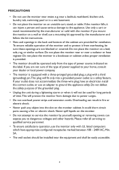
... normal with LCD monitors and do not indicate a problem. Do not repair the screen by yourself! 5 It may remain after switching the image when the same image has been displayed for a long time.The monitor will slowly recover from this. • When the screen becomes black or flashing, or cannot illuminate any more . NOTES • You may find slightly uneven brightness on the screen depending...
... normal with LCD monitors and do not indicate a problem. Do not repair the screen by yourself! 5 It may remain after switching the image when the same image has been displayed for a long time.The monitor will slowly recover from this. • When the screen becomes black or flashing, or cannot illuminate any more . NOTES • You may find slightly uneven brightness on the screen depending...
Dell Monitor Users Guide
Page 6
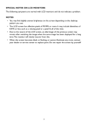
Quick Setup Guide 4. Stand Riser (D2215HC, attached on the LCD monitor) 8. D-SUB Cable 7. Base 6 Safety and Regulatory Information 5. BEFORE YOU OPERATE THE MONITOR FEATURES • 546.01mm (21.5'') TFT Color LCD Monitor • Crisp, Clear Display for Windows • Recommend Resolutions: 1920 x 1080@60Hz • Ergonomic Design • Space Saving, Compact Case Design PACKING LIST The product package should include the following items: 1. Drivers and Documentation media (CD) 3. LCD Monitor 2. Power Cord 6.
Quick Setup Guide 4. Stand Riser (D2215HC, attached on the LCD monitor) 8. D-SUB Cable 7. Base 6 Safety and Regulatory Information 5. BEFORE YOU OPERATE THE MONITOR FEATURES • 546.01mm (21.5'') TFT Color LCD Monitor • Crisp, Clear Display for Windows • Recommend Resolutions: 1920 x 1080@60Hz • Ergonomic Design • Space Saving, Compact Case Design PACKING LIST The product package should include the following items: 1. Drivers and Documentation media (CD) 3. LCD Monitor 2. Power Cord 6.
Dell Monitor Users Guide
Page 9
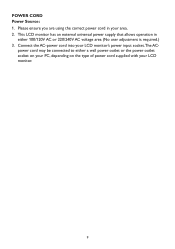
Please ensure you are using the correct power cord in either a wall power outlet or the power outlet socket on your PC, depending on the type of power cord supplied with your LCD monitor's power input socket.The AC- This LCD monitor has an external universal power supply that allows operation in your area. 2. Connect the AC-power cord into your LCD monitor. 9 power cord may be connected to either 100/120V AC or 220/240V AC voltage area (No user adjustment is required.) 3. POWER CORD Power Source: 1.
Please ensure you are using the correct power cord in either a wall power outlet or the power outlet socket on your PC, depending on the type of power cord supplied with your LCD monitor's power input socket.The AC- This LCD monitor has an external universal power supply that allows operation in your area. 2. Connect the AC-power cord into your LCD monitor. 9 power cord may be connected to either 100/120V AC or 220/240V AC voltage area (No user adjustment is required.) 3. POWER CORD Power Source: 1.
Dell Monitor Users Guide
Page 10
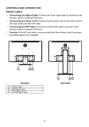
... of the monitor and the computer's VGA port. • Connecting the Power Cord: Connect the AC-power cord to the LCD monitor's AC input socket and the wall outlet. • Connecting the DVI Cable: Connect the 24-pin DVI cable to the back of the monitor and the computer's DVI port. • Caution: If the AC wall outlet is not grounded (with three holes), install the proper grounding adapter (not supplied). 1 23 D2215H 1. DVI Signal input 3. D-SUB Signal input 1 23 D2215HC 10
... of the monitor and the computer's VGA port. • Connecting the Power Cord: Connect the AC-power cord to the LCD monitor's AC input socket and the wall outlet. • Connecting the DVI Cable: Connect the 24-pin DVI cable to the back of the monitor and the computer's DVI port. • Caution: If the AC wall outlet is not grounded (with three holes), install the proper grounding adapter (not supplied). 1 23 D2215H 1. DVI Signal input 3. D-SUB Signal input 1 23 D2215HC 10
Dell Monitor Users Guide
Page 11
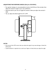
It may cause damage or break the LCD screen. • Careful attention is recommended to look at the full face of the monitor, then adjust the monitor's angle to 90°. 90 o NOTES • Do not touch the LCD screen when you adjust the angle. 11 ADJUSTING THE VIEWING ANGLE (Only for D2215HC) • For optimal viewing, it is required not to catch your own preference. • Hold the stand so you do not topple the monitor when you adjust the monitor's angle. • You can adjust the tilted angle from 0° to your fingers or hands when you adjust the angle.
It may cause damage or break the LCD screen. • Careful attention is recommended to look at the full face of the monitor, then adjust the monitor's angle to 90°. 90 o NOTES • Do not touch the LCD screen when you adjust the angle. 11 ADJUSTING THE VIEWING ANGLE (Only for D2215HC) • For optimal viewing, it is required not to catch your own preference. • Hold the stand so you do not topple the monitor when you adjust the monitor's angle. • You can adjust the tilted angle from 0° to your fingers or hands when you adjust the angle.
Dell Monitor Users Guide
Page 12
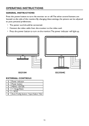
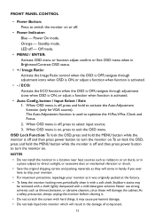
MENU / ENTER 4. + / Image Ratio 5. - / ECO 6. Power button 3. button / Input Select / Exit 12 By changing these settings, the picture can be adjusted to your personal preferences. • The power cord should be connected. • Connect the video cable from the monitor to the video card. • Press the power button to turn on the side of the monitor. Auto Config. Power indicator 2. OPERATING INSTRUCTIONS GENERAL INSTRUCTIONS Press the power button to turn the monitor on or off.The other control buttons are located on the...
MENU / ENTER 4. + / Image Ratio 5. - / ECO 6. Power button 3. button / Input Select / Exit 12 By changing these settings, the picture can be adjusted to your personal preferences. • The power cord should be connected. • Connect the video cable from the monitor to the video card. • Press the power button to turn on the side of the monitor. Auto Config. Power indicator 2. OPERATING INSTRUCTIONS GENERAL INSTRUCTIONS Press the power button to turn the monitor on or off.The other control buttons are located on the...
Dell Monitor Users Guide
Page 13
... off and then press power button to turn the monitor on , press to exit the OSD menu. button / Input Select / Exit: 1. When OSD menu is used to optimize the H.Pos,V.Pos, Clock and Focus. 2. The Auto Adjustment function is off . • Power Indicator: Blue - Power On mode. Never use strong solvents such as they will damage the cabinet.As a safety precaution, always unplug the monitor before cleaning it. • Do not...
... off and then press power button to turn the monitor on , press to exit the OSD menu. button / Input Select / Exit: 1. When OSD menu is used to optimize the H.Pos,V.Pos, Clock and Focus. 2. The Auto Adjustment function is off . • Power Indicator: Blue - Power On mode. Never use strong solvents such as they will damage the cabinet.As a safety precaution, always unplug the monitor before cleaning it. • Do not...
Dell Monitor Users Guide
Page 14
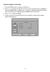
... and save, press the EXIT-button. to enter. Press + or - Press + or - Luminance Contrast 50 Brightness 90 Eco Mode Standard AUTO :Exit :Move MENU :Select 14 HOW TO ADJUST A SETTING 1. again to navigate through the menu items. Once the desired item is highlighted, press MENU-button to display the OSD menu. 2. Press the MENU-button to activate it. 3. Once the desired item is highlighted, press the MENU-button to...
... and save, press the EXIT-button. to enter. Press + or - Press + or - Luminance Contrast 50 Brightness 90 Eco Mode Standard AUTO :Exit :Move MENU :Select 14 HOW TO ADJUST A SETTING 1. again to navigate through the menu items. Once the desired item is highlighted, press MENU-button to display the OSD menu. 2. Press the MENU-button to activate it. 3. Once the desired item is highlighted, press the MENU-button to...
Dell Monitor Users Guide
Page 15
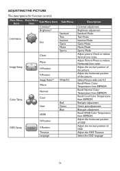
... Clock Image Setup Phase H.Position V.Position Image Ratio** Warm Wide/4:3 Normal Color Temp. Red gain adjustment Green gain adjustment Blue gain adjustment Recall SRGB Color Temperature from EEPROM. Adjust Picture Phase to reduce Vertical-Line noise. Cool User sRGB Red Green Blue H.Position OSD Setup V.Position Timeout Language Description Contrast adjustment Brightness adjustment Standard Mode Text Mode Internet Mode Game Mode Movie Mode Sports Mode Adjust picture Clock to reduce Horizontal-Line noise Adjust the vertical position of the picture. Recall Cool Color Temperature...
... Clock Image Setup Phase H.Position V.Position Image Ratio** Warm Wide/4:3 Normal Color Temp. Red gain adjustment Green gain adjustment Blue gain adjustment Recall SRGB Color Temperature from EEPROM. Adjust Picture Phase to reduce Vertical-Line noise. Cool User sRGB Red Green Blue H.Position OSD Setup V.Position Timeout Language Description Contrast adjustment Brightness adjustment Standard Mode Text Mode Internet Mode Game Mode Movie Mode Sports Mode Adjust picture Clock to reduce Horizontal-Line noise Adjust the vertical position of the picture. Recall Cool Color Temperature...
Dell Monitor Users Guide
Page 16
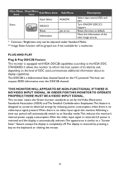
... automatically switch to default. Show the information of DDC used, communicate additional information about its identity and, depending on the level of the main image source. * Contrast / Brightness only can request EDID information over the DDC2B channel. The DDC2B is no Description Select input source VGA and DVI Turn ON/OFF DDC/CI Support Reset the menu to an Standby mode.This reduces the monitor's internal power supply consumption...
... automatically switch to default. Show the information of DDC used, communicate additional information about its identity and, depending on the level of the main image source. * Contrast / Brightness only can request EDID information over the DDC2B channel. The DDC2B is no Description Select input source VGA and DVI Turn ON/OFF DDC/CI Support Reset the menu to an Standby mode.This reduces the monitor's internal power supply consumption...
Dell Monitor Users Guide
Page 17
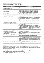
... white) Poor brightness or contrast Horizontal or vertical disturbances on the screen Possible Solution • Check if the Power Switch is in the ON position. • Power Cord should be in light picture. CLOCK (pixel frequency) controls the number of the primary colors (RED, GREEN, or BLUE) Screen image is not correct, the screen shows vertical stripes and the picture does not have correct width. The LED should be snugly seated in its slot. • Make sure monitor's video cable is properly connected...
... white) Poor brightness or contrast Horizontal or vertical disturbances on the screen Possible Solution • Check if the Power Switch is in the ON position. • Power Cord should be in light picture. CLOCK (pixel frequency) controls the number of the primary colors (RED, GREEN, or BLUE) Screen image is not correct, the screen shows vertical stripes and the picture does not have correct width. The LED should be snugly seated in its slot. • Make sure monitor's video cable is properly connected...

Dell Monitor Users Guide
Page 18
INPUT NOT SUPPORTED Your computer has been set to display mode given in the table on page 20. 18 ERROR MESSAGE AND POSSIBLE SOLUTION NO SIGNAL 1. Check that the signal-cable is loose, tighten the connector's screws. 2. Check the signal-cable's connection pins for damage. If the connector is properly connected. Set the computer to unsuitable display mode.
INPUT NOT SUPPORTED Your computer has been set to display mode given in the table on page 20. 18 ERROR MESSAGE AND POSSIBLE SOLUTION NO SIGNAL 1. Check that the signal-cable is loose, tighten the connector's screws. 2. Check the signal-cable's connection pins for damage. If the connector is properly connected. Set the computer to unsuitable display mode.

Dell Monitor Users Guide
Page 19
Resolution Plug & Play Power Consumption Separate Sync. H-Frequency V-Frequency ON Mode Standby Mode OFF Mode Input Connector Input Video Signal Maximum Screen Size Power Source Environmental Considerations Dimensions Weight (N.W.): Weight (with packaging): 21.5" TFT Color LCD 546.01 mm diagonal 0.24825 mm(H)×0.24825 mm(V) R, G, B Analog Interface Digital H/V TTL 30 kHz - 83 kHz 56 Hz - 76 Hz 16.7 M Colors 170 MHz 1920 x 1080 @ 60Hz VESA DDC2B™ ≤ 30 W ≤ 0.5 W ≤ 0.5 W D-Sub 15 pin DVI 24 pin...
Resolution Plug & Play Power Consumption Separate Sync. H-Frequency V-Frequency ON Mode Standby Mode OFF Mode Input Connector Input Video Signal Maximum Screen Size Power Source Environmental Considerations Dimensions Weight (N.W.): Weight (with packaging): 21.5" TFT Color LCD 546.01 mm diagonal 0.24825 mm(H)×0.24825 mm(V) R, G, B Analog Interface Digital H/V TTL 30 kHz - 83 kHz 56 Hz - 76 Hz 16.7 M Colors 170 MHz 1920 x 1080 @ 60Hz VESA DDC2B™ ≤ 30 W ≤ 0.5 W ≤ 0.5 W D-Sub 15 pin DVI 24 pin...

Dell Monitor Users Guide
Page 20
FACTORY PRESET TIMING TABLE STANDARD VGA XGA SXGA FULL HD DOS RESOLUTION HORIZONTAL VERTICAL FREQUENCY (KHz) FREQUENCY (Hz) 640 × 480@60Hz 31.469 59.940 640 × 480@75Hz 37.500 75.000 800 × 600@60Hz 37.879 60.317 800 × 600@75Hz 46.875 75.000 1024 × 768@60Hz 48.363 60.004 1024 × 768@75Hz 60.023 75.029 1280 ×1024@60Hz 63.981 60.000 1280 ×1024@75Hz 79.976 75.025 1152 ×864@75Hz 67.500 75.000 1920 x 1080@60Hz 67.500 60.000 720 x 400@70Hz 31.469 70.087 20
FACTORY PRESET TIMING TABLE STANDARD VGA XGA SXGA FULL HD DOS RESOLUTION HORIZONTAL VERTICAL FREQUENCY (KHz) FREQUENCY (Hz) 640 × 480@60Hz 31.469 59.940 640 × 480@75Hz 37.500 75.000 800 × 600@60Hz 37.879 60.317 800 × 600@75Hz 46.875 75.000 1024 × 768@60Hz 48.363 60.004 1024 × 768@75Hz 60.023 75.029 1280 ×1024@60Hz 63.981 60.000 1280 ×1024@75Hz 79.976 75.025 1152 ×864@75Hz 67.500 75.000 1920 x 1080@60Hz 67.500 60.000 720 x 400@70Hz 31.469 70.087 20

Dell Monitor Users Guide
Page 21
.... 13. 14. 15. Pin Color Display Signal Cable PIN NO. 1. 2. 3. 4. 5. 6. 7. 8. 9. 10. 11. 12. DESCRIPTION Red Green Blue Ground Detect Cable R-Ground G-Ground B-Ground 1 8 9 16 17 24 24 - TMDS Data 1TMDS Data 1+ TMDS Data 1/3 Shield TMDS Data 3- CONNECTOR PIN ASSIGNMENT 1 5 6 10 11 15 15 - DESCRIPTION +5V Ground Ground DDC-Serial Data H-Sync V-Sync DDC-Serial Clock DESCRIPTION TMDS Data 3+ +5V Power Ground(for+5V) Hot...
.... 13. 14. 15. Pin Color Display Signal Cable PIN NO. 1. 2. 3. 4. 5. 6. 7. 8. 9. 10. 11. 12. DESCRIPTION Red Green Blue Ground Detect Cable R-Ground G-Ground B-Ground 1 8 9 16 17 24 24 - TMDS Data 1TMDS Data 1+ TMDS Data 1/3 Shield TMDS Data 3- CONNECTOR PIN ASSIGNMENT 1 5 6 10 11 15 15 - DESCRIPTION +5V Ground Ground DDC-Serial Data H-Sync V-Sync DDC-Serial Clock DESCRIPTION TMDS Data 3+ +5V Power Ground(for+5V) Hot...


