
Service Manual
Page 1
SCC-L04K-A Picture tube Phosphor Type Transmission Ratio Faceplate Viewable image size Resolution Horizontal Vertical Display picture size Input signal Video Sync N3 CHASSIS SPECIFICATIONS 0.25 - 0.27 mm aperture grill pitch, 21 inches measured diagonally, 90 degree deflection P22 Approx. 39% Anti Reflective (AR)/Anti Static (AS) coating Approx. 403.8... (Non-condensing) Non-operating 5% to 90% (Non-condensing) Design and specifications are subject to change without notice. COLOR MONITOR R SERVICE MANUAL D1626HT US Model Canadian Model AEP Model EQ Model SH Model J Model Chassis No.
SCC-L04K-A Picture tube Phosphor Type Transmission Ratio Faceplate Viewable image size Resolution Horizontal Vertical Display picture size Input signal Video Sync N3 CHASSIS SPECIFICATIONS 0.25 - 0.27 mm aperture grill pitch, 21 inches measured diagonally, 90 degree deflection P22 Approx. 39% Anti Reflective (AR)/Anti Static (AS) coating Approx. 403.8... (Non-condensing) Non-operating 5% to 90% (Non-condensing) Design and specifications are subject to change without notice. COLOR MONITOR R SERVICE MANUAL D1626HT US Model Canadian Model AEP Model EQ Model SH Model J Model Chassis No.

Service Manual
Page 4
... 5-4. A Board Removal 14 2-5. H and J Boards Removal 16 2-9. Frame Shcematic Diagram 27 5-3. D Board Removal 13 2-3. SAFETY RELATED ADJUSTMENT 18 4. ADJUSTMENTS 19 5. Service Position 16 2-8. Block Diagrams 21 5-2. Chassis 51 6-2. DIAGRAMS 5-1. Picture Tube 52 6-3.
... 5-4. A Board Removal 14 2-5. H and J Boards Removal 16 2-9. Frame Shcematic Diagram 27 5-3. D Board Removal 13 2-3. SAFETY RELATED ADJUSTMENT 18 4. ADJUSTMENTS 19 5. Service Position 16 2-8. Block Diagrams 21 5-2. Chassis 51 6-2. DIAGRAMS 5-1. Picture Tube 52 6-3.

Service Manual
Page 11
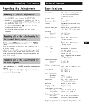
... and specifications are not reset to the factory settings. TechnicaGl eFtetiantgureSstarted Specifications Picture tube 0.25 - 0.27 mm aperture grill pitch, 21 inches measured diagonally, 90 degree deflection Phosphor Type P22 Transmission Ratio Approx. 39% Faceplate Anti Reflective (AR)/Anti Static (AS) ... reset this specific adjustment. Customizing Your Monitor Resetting the Adjustments Resetting a specific adjustment: 1 Press the MENU button to display the MENU OSD 2 Highlight the OSD containing the adjustment you want to reset using the BRIGHTNESS and CONTRAST buttons and ...
... and specifications are not reset to the factory settings. TechnicaGl eFtetiantgureSstarted Specifications Picture tube 0.25 - 0.27 mm aperture grill pitch, 21 inches measured diagonally, 90 degree deflection Phosphor Type P22 Transmission Ratio Approx. 39% Faceplate Anti Reflective (AR)/Anti Static (AS) ... reset this specific adjustment. Customizing Your Monitor Resetting the Adjustments Resetting a specific adjustment: 1 Press the MENU button to display the MENU OSD 2 Highlight the OSD containing the adjustment you want to reset using the BRIGHTNESS and CONTRAST buttons and ...
Service Manual
Page 12
...Design and specifications are reset to the factory settings. TechnicaGl eFtetiantgureSstarted Specifications Picture tube 0.25 - 0.27 mm aperture grill pitch, 21 inches measured diagonally, 90 degree deflection Phosphor Type P22 Transmission Ratio Approx. 39% Faceplate Anti Reflective (AR)/Anti Static (AS)... size Approx. 403.8 × 302.2 mm (w/h) (16 × 12 in.) 19.8" viewing image Resolution Horizontal Vertical Max. 1600 dots Max. 1200 lines Display picture size Approx. 388 × 291 mm (w/h) (15 3/8 × 11 1/2 in.) or Approx. 364 × 291 mm (w/h) EN (14 3/8...
...Design and specifications are reset to the factory settings. TechnicaGl eFtetiantgureSstarted Specifications Picture tube 0.25 - 0.27 mm aperture grill pitch, 21 inches measured diagonally, 90 degree deflection Phosphor Type P22 Transmission Ratio Approx. 39% Faceplate Anti Reflective (AR)/Anti Static (AS)... size Approx. 403.8 × 302.2 mm (w/h) (16 × 12 in.) 19.8" viewing image Resolution Horizontal Vertical Max. 1600 dots Max. 1200 lines Display picture size Approx. 388 × 291 mm (w/h) (15 3/8 × 11 1/2 in.) or Approx. 364 × 291 mm (w/h) EN (14 3/8...
Service Manual
Page 20
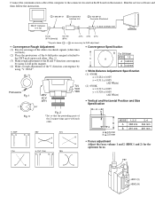
...cable of the computer to the connector located on the D board on black). (2) Place the protrusions of the 6-fold poles magnet attached to the CRT neck upon each other . (Fig. 1) (3) Make rough adjustment of the H and V direction convergence by using 4-fold poles magnet. (4) ...Make a rough adjustment of the V direction convergence by using "V. IBM AT Computer as a Jig 1 1-690-391-21 2 A-1500-819-A Interface Unit 3 3-702-691-01 Connector Attachment To BUS CONNECTOR D-sub (9 Pin [female]) mini Din (8Pin) 4 Pin 4 Pin 4 Pin *...
...cable of the computer to the connector located on the D board on black). (2) Place the protrusions of the 6-fold poles magnet attached to the CRT neck upon each other . (Fig. 1) (3) Make rough adjustment of the H and V direction convergence by using 4-fold poles magnet. (4) ...Make a rough adjustment of the V direction convergence by using "V. IBM AT Computer as a Jig 1 1-690-391-21 2 A-1500-819-A Interface Unit 3 3-702-691-01 Connector Attachment To BUS CONNECTOR D-sub (9 Pin [female]) mini Din (8Pin) 4 Pin 4 Pin 4 Pin *...

Service Manual
Page 21
... 5 DIAGRAMS J(POWER SW) CN891 AC L IN 3 AC L OUT 1 S891 POWER 3 AC L IN 1 AC L OUT AC INLET DGC G(POWER SUPPLY) CN604 AC L 1 AC N 3 F601 6.3A T601 21 34 CN605 TH601 CN603 DGC 4 DGC 1 RY602 THP601 RELAY DRIVE Q690 RY601 RELAY DRIVE Q660 D610 D663 L610 18 12 9 D611 BOOST CONV OUT Q610... 15 LED3 39 KEY_DET 44 P65/AN5 45 P66/AN6 20 RXD 19 TXD 9 ASC SW 16 OSD_SEL 10 DAC SEL 60 HFBP 65 VRET 21 DMP_CLK 22 DMP_DO 24 DMP_DI 17 DMP_ID 53 LOWB_DET 79 INPUT SEL 40 VX 46 VY 74 H CONV 100 DGC 99 HTR SW 98 POWER...
... 5 DIAGRAMS J(POWER SW) CN891 AC L IN 3 AC L OUT 1 S891 POWER 3 AC L IN 1 AC L OUT AC INLET DGC G(POWER SUPPLY) CN604 AC L 1 AC N 3 F601 6.3A T601 21 34 CN605 TH601 CN603 DGC 4 DGC 1 RY602 THP601 RELAY DRIVE Q690 RY601 RELAY DRIVE Q660 D610 D663 L610 18 12 9 D611 BOOST CONV OUT Q610... 15 LED3 39 KEY_DET 44 P65/AN5 45 P66/AN6 20 RXD 19 TXD 9 ASC SW 16 OSD_SEL 10 DAC SEL 60 HFBP 65 VRET 21 DMP_CLK 22 DMP_DO 24 DMP_DI 17 DMP_ID 53 LOWB_DET 79 INPUT SEL 40 VX 46 VY 74 H CONV 100 DGC 99 HTR SW 98 POWER...

Service Manual
Page 25
...C001 0.01 B:CHIP R020 1k :CHIP 1 2 3 4 5 6 7 8 9 10 11 12 13 14 15 16 17 18 19 20 21 22 23 24 25 26 27 28 29 30 R088 2.2k :CHIP R089 2.2k :CHIP ASC_SW DAC_SEL VSS LED0 LED1 LED2 LED3 OSD_SEL DMP-ID... GND1 D025 UDZ-TE-17-7.5B 14 13 12 11 10 9 8 7 6 5 4 3 2 1 15 16 17 18 19 20 21 22 23 24 25 26 27 28 IO G C057 47 C042 47 IC003 NJM78L09A-T3 9V REG +9V IO 9V-2 G C079 47 C080 ...B:CHIP 39 CLPOUT 40 VCCP 41 HS/CS1 42 HS/CS2 43 VS1 44 VS2 IC007 CXA2043Q DEFLECTION PROCESS VSPDM 22 VSHPR 21 VSHPC 20 VSHAPE 19 VSHPLVL 18 PEAKDET 17 R057 C060 15k 10 :RN-CP C062 0.1 25V B:CHIP C063 0.1 :PT ...
...C001 0.01 B:CHIP R020 1k :CHIP 1 2 3 4 5 6 7 8 9 10 11 12 13 14 15 16 17 18 19 20 21 22 23 24 25 26 27 28 29 30 R088 2.2k :CHIP R089 2.2k :CHIP ASC_SW DAC_SEL VSS LED0 LED1 LED2 LED3 OSD_SEL DMP-ID... GND1 D025 UDZ-TE-17-7.5B 14 13 12 11 10 9 8 7 6 5 4 3 2 1 15 16 17 18 19 20 21 22 23 24 25 26 27 28 IO G C057 47 C042 47 IC003 NJM78L09A-T3 9V REG +9V IO 9V-2 G C079 47 C080 ...B:CHIP 39 CLPOUT 40 VCCP 41 HS/CS1 42 HS/CS2 43 VS1 44 VS2 IC007 CXA2043Q DEFLECTION PROCESS VSPDM 22 VSHPR 21 VSHPC 20 VSHAPE 19 VSHPLVL 18 PEAKDET 17 R057 C060 15k 10 :RN-CP C062 0.1 25V B:CHIP C063 0.1 :PT ...

Service Manual
Page 28
... of A Board D1626HT D1626HT CONNECTOR RANEL TO D BOARD CN511 54321 10 9 8 7 6 15 14 13 12 11 HD15 VD HD B GR 5BNC • A BOARD WAVEFORMS 1 6 3.0 Vp-p (H) 2 37.0 Vp-p (H) 7 35.0 Vp-p ... CH:CHIP 47p CH:CHIP 47 :RN-CP 1000p CH:CHIP 2.2k :CHIP 18 17 16 15 14 13 12 11 10 9 8 7 6 5 4 3 2 1 19 20 21 22 23 24 25 26 27 28 29 30 31 32 33 34 35 36 26 25 24 23 22... 2P WHT :VH 1KV N.C. G_IN VBB GND VBB R_IN R_E.P. TO D BOARD CN507 14 13 12 11 10 9 8 7 6 5 4 3 2 1 15 16 17 18 19 20 21 22 23 24 25 26 27 28 10 9 8 7 6 5 4 3 2 1 11 12 13 14 15 16 17 18 19 20 NC PWM0 NC PWM1 R447 470 :CHIP...
... of A Board D1626HT D1626HT CONNECTOR RANEL TO D BOARD CN511 54321 10 9 8 7 6 15 14 13 12 11 HD15 VD HD B GR 5BNC • A BOARD WAVEFORMS 1 6 3.0 Vp-p (H) 2 37.0 Vp-p (H) 7 35.0 Vp-p ... CH:CHIP 47p CH:CHIP 47 :RN-CP 1000p CH:CHIP 2.2k :CHIP 18 17 16 15 14 13 12 11 10 9 8 7 6 5 4 3 2 1 19 20 21 22 23 24 25 26 27 28 29 30 31 32 33 34 35 36 26 25 24 23 22... 2P WHT :VH 1KV N.C. G_IN VBB GND VBB R_IN R_E.P. TO D BOARD CN507 14 13 12 11 10 9 8 7 6 5 4 3 2 1 15 16 17 18 19 20 21 22 23 24 25 26 27 28 10 9 8 7 6 5 4 3 2 1 11 12 13 14 15 16 17 18 19 20 NC PWM0 NC PWM1 R447 470 :CHIP...

Service Manual
Page 31
...BOARD 18 * 4-382-848-01 HOLDER, PRINTED CIRCUIT BOARD 19 * 3-703-141-00 HOLDER, PRINTED CIRCUIT BOARD 20 * 8-933-277-00 G BOARD, COMPLETE 21 21 * 8-933-269-00 GA BOARD, COMPLETE 22 * 4-061-604-31 CABINET 23 * 4-061-605-31 COVER, SCREW 24 * 4-060-358-41 COVER, ... INFORMATION 26 * 1-543-793-11 FILTER, CLAMP (FEPRITE CORE) 27 * 4-061-694-02 SHEET, INSULATE DESCRIPTION REMARK 1 * X-4035-195-1 BEZEL ASSY 2, 3 2 * 4-061-970-21 BUTTON, POWER 3 4-042-593-01 SPRING, COMPRESSION 4 * 8-933-283-00 H BOARD, COMPLETE 5 4-029-432-01 SCREW (3X12), (+) BVWHTP 6 4-365-808-01 SCREW (5), TAPPING...
...BOARD 18 * 4-382-848-01 HOLDER, PRINTED CIRCUIT BOARD 19 * 3-703-141-00 HOLDER, PRINTED CIRCUIT BOARD 20 * 8-933-277-00 G BOARD, COMPLETE 21 21 * 8-933-269-00 GA BOARD, COMPLETE 22 * 4-061-604-31 CABINET 23 * 4-061-605-31 COVER, SCREW 24 * 4-060-358-41 COVER, ... INFORMATION 26 * 1-543-793-11 FILTER, CLAMP (FEPRITE CORE) 27 * 4-061-694-02 SHEET, INSULATE DESCRIPTION REMARK 1 * X-4035-195-1 BEZEL ASSY 2, 3 2 * 4-061-970-21 BUTTON, POWER 3 4-042-593-01 SPRING, COMPRESSION 4 * 8-933-283-00 H BOARD, COMPLETE 5 4-029-432-01 SCREW (3X12), (+) BVWHTP 6 4-365-808-01 SCREW (5), TAPPING...

Service Manual
Page 38
... D613 8-719-110-49 ZENER DIODE RD18ESB2 D614 8-719-977-28 DIODE DTZ10B L610 L611 L670 L671 L672 1-416-409-11 COIL, CHOKE 1-406-664-21 COIL, CHOKE 1-412-529-11 INDUCTOR 1-412-529-11 INDUCTOR 1-412-529-11 INDUCTOR 68UH 22UH 22UH 22UH L673 1-412-529-11 INDUCTOR L691 1-412...-11 HOLDER, FUSE ; Ne les remplacer que par une piéce portant le numéro spécifié. G REF.NO. PART NO. D1626HT The components identified by shading and mark ¡ are critical for safety. PART NO. Replace only with part number specified. F601 FB610 1-410-396-41...
... D613 8-719-110-49 ZENER DIODE RD18ESB2 D614 8-719-977-28 DIODE DTZ10B L610 L611 L670 L671 L672 1-416-409-11 COIL, CHOKE 1-406-664-21 COIL, CHOKE 1-412-529-11 INDUCTOR 1-412-529-11 INDUCTOR 1-412-529-11 INDUCTOR 68UH 22UH 22UH 22UH L673 1-412-529-11 INDUCTOR L691 1-412...-11 HOLDER, FUSE ; Ne les remplacer que par une piéce portant le numéro spécifié. G REF.NO. PART NO. D1626HT The components identified by shading and mark ¡ are critical for safety. PART NO. Replace only with part number specified. F601 FB610 1-410-396-41...

Service Manual
Page 46
... 1-215-433-00 METAL 680 1K 1K 2.2K 3.3K 1% 1/4W 1% 1/4W 1% 1/4W 1% 1/4W 1% 1/4W T501 T502 T503 T504 T701 1-429-303-21 TRANSFORMER, FERRITE (HDT) 1-416-401-11 COIL, CHOKE 5MMH 1-431-413-11 TRANSFORMER, FERRITE (HST) 1-416-257-11 COIL, CHOKE (HCC) 2.0MH 1-431-414... S805 S806 1-692-431-21 SWITCH, TACTILE (CONT+) 1-692-431-21 SWITCH, TACTILE (CONT-) 1-692-431-21 SWITCH, TACTILE (MENU) 1-692-431-21 SWITCH, TACTILE (BRT+) 1-692-431-21 SWITCH, TACTILE (BRT-) S818 1-692-431-21 SWITCH, TACTILE (ASC) S820 1-692-431-21 SWITCH, TACTILE (RESET) - 67 - D1626HT The components identified by shading...
... 1-215-433-00 METAL 680 1K 1K 2.2K 3.3K 1% 1/4W 1% 1/4W 1% 1/4W 1% 1/4W 1% 1/4W T501 T502 T503 T504 T701 1-429-303-21 TRANSFORMER, FERRITE (HDT) 1-416-401-11 COIL, CHOKE 5MMH 1-431-413-11 TRANSFORMER, FERRITE (HST) 1-416-257-11 COIL, CHOKE (HCC) 2.0MH 1-431-414... S805 S806 1-692-431-21 SWITCH, TACTILE (CONT+) 1-692-431-21 SWITCH, TACTILE (CONT-) 1-692-431-21 SWITCH, TACTILE (MENU) 1-692-431-21 SWITCH, TACTILE (BRT+) 1-692-431-21 SWITCH, TACTILE (BRT-) S818 1-692-431-21 SWITCH, TACTILE (ASC) S820 1-692-431-21 SWITCH, TACTILE (RESET) - 67 - D1626HT The components identified by shading...
