

Service Manual
Page 4
... Secure boot...72 Secure boot...73 Updating the BIOS in Windows ...73 Updating BIOS on systems with BitLocker enabled 74 Updating your system BIOS using a USB flash drive 74 Flashing the BIOS from the F12 One-Time boot menu...75 System and setup password...76 Assigning a system setup password...76 Deleting or changing an existing system setup password 76 Clearing CMOS settings...77 Clearing BIOS (System Setup) and System passwords 77 Chapter 5: Troubleshooting...78 Recovering the operating system...78 System diagnostic lights...78 Flea power release...79 WiFi power...
... Secure boot...72 Secure boot...73 Updating the BIOS in Windows ...73 Updating BIOS on systems with BitLocker enabled 74 Updating your system BIOS using a USB flash drive 74 Flashing the BIOS from the F12 One-Time boot menu...75 System and setup password...76 Assigning a system setup password...76 Deleting or changing an existing system setup password 76 Clearing CMOS settings...77 Clearing BIOS (System Setup) and System passwords 77 Chapter 5: Troubleshooting...78 Recovering the operating system...78 System diagnostic lights...78 Flea power release...79 WiFi power...

Service Manual
Page 6
... and exit all attached devices from your computer and all open applications. 2. Safety instructions Use the following safety guidelines to protect your computer from the media-card reader. Some cables have read the safety information that shipped with the product or at www.dell.com/regulatory_compliance. NOTE: Before working inside your operating system for shut-down instructions. 3. Click Start > Power > Shut down your computer...
... and exit all attached devices from your computer and all open applications. 2. Safety instructions Use the following safety guidelines to protect your computer from the media-card reader. Some cables have read the safety information that shipped with the product or at www.dell.com/regulatory_compliance. NOTE: Before working inside your operating system for shut-down instructions. 3. Click Start > Power > Shut down your computer...

Service Manual
Page 7
... as bonding. It is critical to accommodate the type of intermittent failures means that is known as expansion cards, processors, memory DIMMs, and system boards. Very slight charges can be aware that the internal wires of memory integrity, intermittent memory errors, etc. Use only Field Service kits with additional space to keep ESD sensitive devices, such as plastic heat sink casings, away...
... as bonding. It is critical to accommodate the type of intermittent failures means that is known as expansion cards, processors, memory DIMMs, and system boards. Very slight charges can be aware that the internal wires of memory integrity, intermittent memory errors, etc. Use only Field Service kits with additional space to keep ESD sensitive devices, such as plastic heat sink casings, away...

Service Manual
Page 8
... all insulator parts while performing service and that the new part arrived in the system, or inside your computer may severely damage your computer. 3. Get a firm balanced footing. Avoid twisting your toes out. 2. Replace any media cards, discs, or any other plastics should always be moved at an ESD-protected work area, insulators such as replacement parts or parts to be used in...
... all insulator parts while performing service and that the new part arrived in the system, or inside your computer may severely damage your computer. 3. Get a firm balanced footing. Avoid twisting your toes out. 2. Replace any media cards, discs, or any other plastics should always be moved at an ESD-protected work area, insulators such as replacement parts or parts to be used in...

Service Manual
Page 15
... assembly. 4. Connect the battery cable to default. Next steps 1. When an RTC Reset cycle occurs, the system turns on the base cover. 5. An "Invalid Configuration" error message is recommended that you to the battery and other system components. • If the battery gets stuck inside your computer. CAUTION: Removing the battery resets the BIOS setup program's settings to the system board. 2. The following image(s) indicate the location of the battery and...
... assembly. 4. Connect the battery cable to default. Next steps 1. When an RTC Reset cycle occurs, the system turns on the base cover. 5. An "Invalid Configuration" error message is recommended that you to the battery and other system components. • If the battery gets stuck inside your computer. CAUTION: Removing the battery resets the BIOS setup program's settings to the system board. 2. The following image(s) indicate the location of the battery and...

Service Manual
Page 49
... IO-board. 9. Next steps 1. Install the M.2 2280 solid-state drive. (if applicable) 5. About this task The following table provides the antenna-cable color scheme for the wireless card supported by your computer. Remove the battery. 4. Remove the M.2 2230 WWAN/solid-state drive. (if applicable) 7. Table 3. Antenna-cable color scheme Connectors on the wireless card Main (white triangle) Antenna-cable color White Auxiliary (black triangle) Black 20.Connect the power-button cable...
... IO-board. 9. Next steps 1. Install the M.2 2280 solid-state drive. (if applicable) 5. About this task The following table provides the antenna-cable color scheme for the wireless card supported by your computer. Remove the battery. 4. Remove the M.2 2230 WWAN/solid-state drive. (if applicable) 7. Table 3. Antenna-cable color scheme Connectors on the wireless card Main (white triangle) Antenna-cable color White Auxiliary (black triangle) Black 20.Connect the power-button cable...
Service Manual
Page 67
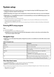
... applicable. Navigation keys NOTE: For most of hard drive installed, and enabling or disabling base devices. Expands or collapses a drop-down the BIOS Setup program screen information for the following purposes: • Get information about the hardware installed in the field. NOTE: Depending on your computer work incorrectly. One time boot menu To enter one -time boot menu displays the devices that you make your computer. 2. The one time boot menu, turn off your...
... applicable. Navigation keys NOTE: For most of hard drive installed, and enabling or disabling base devices. Expands or collapses a drop-down the BIOS Setup program screen information for the following purposes: • Get information about the hardware installed in the field. NOTE: Depending on your computer work incorrectly. One time boot menu To enter one -time boot menu displays the devices that you make your computer. 2. The one time boot menu, turn off your...

Service Manual
Page 69
... Control Integrated NIC Power on from Standby. • Enable USB Wake Support Default: Disabled NOTE: If USB PowerShare is enabled, a device that is always enabled during POST. USB emulation is connected to charge external devices using the stored system battery power through the USB PowerShare port when the computer is turned off and not visible to turn on LID open USB Emulation USB PowerShare USB Wake Support Description • Enable Intel SpeedStep Default: Enabled Enables or disables the Intel Speed Shift Technology. This option enables...
... Control Integrated NIC Power on from Standby. • Enable USB Wake Support Default: Disabled NOTE: If USB PowerShare is enabled, a device that is always enabled during POST. USB emulation is connected to charge external devices using the stored system battery power through the USB PowerShare port when the computer is turned off and not visible to turn on LID open USB Emulation USB PowerShare USB Wake Support Description • Enable Intel SpeedStep Default: Enabled Enables or disables the Intel Speed Shift Technology. This option enables...

Service Manual
Page 70
... memory size for AHCI mode • RAID On: SATA is configured to support RAID mode Default: RAID On Enables or disables the system setup (BIOS) warning messages when you use certain power adapters. • Enable Adapter Warnings Default: Enabled Enables you to configure the operating mode of the following options: • Disabled: The SATA controllers are : • Enabled • Disabled Default: Disabled Enables or disables booting from storage devices connected to set Displays if the system password is unlocked. Default: Function key Displays the battery health. Default: Disabled...
... memory size for AHCI mode • RAID On: SATA is configured to support RAID mode Default: RAID On Enables or disables the system setup (BIOS) warning messages when you use certain power adapters. • Enable Adapter Warnings Default: Enabled Enables you to configure the operating mode of the following options: • Disabled: The SATA controllers are : • Enabled • Disabled Default: Disabled Enables or disables booting from storage devices connected to set Displays if the system password is unlocked. Default: Function key Displays the battery health. Default: Disabled...

Service Manual
Page 71
... of your password. If disabled the setup options are : • Enter the old password: • Enter the new password: • Confirm new password: Click OK once you to "Not set the password. NOTE: For the first time login, "Enter the old password:" field is enabled by default. The entries to always set strong password. • Enable Strong Password This option is not set password are locked by the admin password. • Allow Wireless Switch Changes This option is enabled by default. Password Change Allows...
... of your password. If disabled the setup options are : • Enter the old password: • Enter the new password: • Confirm new password: Click OK once you to "Not set the password. NOTE: For the first time login, "Enter the old password:" field is enabled by default. The entries to always set strong password. • Enable Strong Password This option is not set password are locked by the admin password. • Allow Wireless Switch Changes This option is enabled by default. Password Change Allows...

Service Manual
Page 72
... the options: • Secure Boot Enable • Secure Boot Disable Default: Enabled Enables or disables the Legacy Option ROMs. Default: Disabled Enables or disables Attempt Legacy Boot. When enabled, this setting take effect immediately. Enables you to enable the Trusted Platform Module (TPM) during POST. Default: Disabled Displays the boot sequence. Security (continued) Option Description • PPI Bypass for Enable Command-Default • PPI Bypass for Disbale Command • PPI Bypass for Clear Command Enables you to skip BIOS PPI user prompts...
... the options: • Secure Boot Enable • Secure Boot Disable Default: Enabled Enables or disables the Legacy Option ROMs. Default: Disabled Enables or disables Attempt Legacy Boot. When enabled, this setting take effect immediately. Enables you to enable the Trusted Platform Module (TPM) during POST. Default: Disabled Displays the boot sequence. Security (continued) Option Description • PPI Bypass for Enable Command-Default • PPI Bypass for Disbale Command • PPI Bypass for Clear Command Enables you to skip BIOS PPI user prompts...

Service Manual
Page 73
...boot option. Secure Boot Option Boot List Option File Browser Add Boot Option File Browser Del Boot Option Secure Boot Legacy Option ROMs Attempt Legacy Boot Boot Option Priorities Boot Option #1 Boot Option #2 Boot Option #3 Updating the BIOS in Windows Description Displays the available boot options. • Legacy • UEFI Default: UEFI Enables you replace the system board or if an update is completed. Default: Disabled Displays the boot sequence. Go to update your computer battery is recommended to www.dell.com/support. • Enter the Service Tag or Express Service Code...
...boot option. Secure Boot Option Boot List Option File Browser Add Boot Option File Browser Del Boot Option Secure Boot Legacy Option ROMs Attempt Legacy Boot Boot Option Priorities Boot Option #1 Boot Option #2 Boot Option #3 Updating the BIOS in Windows Description Displays the available boot options. • Legacy • UEFI Default: UEFI Enables you replace the system board or if an update is completed. Default: Disabled Displays the boot sequence. Go to update your computer battery is recommended to www.dell.com/support. • Enter the Service Tag or Express Service Code...
Service Manual
Page 74
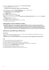
... BitLocker enabled CAUTION: If BitLocker is still a need to display the One Time Boot Menu. 5. NOTE: You must use a bootable USB flash drive. Steps 1. The Drivers and Downloads section is displayed. If you reboot the system it myself. 8. Select your computer model and the Product Support page of your computer appears. 6. Click Get drivers, and then click Drivers and Downloads. Follow the on -screen instructions. 74 Updating BIOS on your system BIOS using a USB flash drive About...
... BitLocker enabled CAUTION: If BitLocker is still a need to display the One Time Boot Menu. 5. NOTE: You must use a bootable USB flash drive. Steps 1. The Drivers and Downloads section is displayed. If you reboot the system it myself. 8. Select your computer model and the Product Support page of your computer appears. 6. Click Get drivers, and then click Drivers and Downloads. Follow the on -screen instructions. 74 Updating BIOS on your system BIOS using a USB flash drive About...

Service Manual
Page 75
... external USB device. 5. The computer will restart after 2012 have to the root of the computer. 2. Select the file and double-click the flash target file, and then click Submit. 6. The computer restarts to access the One-Time Boot Menu, select BIOS Update using the mouse or arrow keys then press Enter. The computer may not boot if you copied the flash into a USB port of the USB drive...
... external USB device. 5. The computer will restart after 2012 have to the root of the computer. 2. Select the file and double-click the flash target file, and then click Submit. 6. The computer restarts to access the One-Time Boot Menu, select BIOS Update using the mouse or arrow keys then press Enter. The computer may not boot if you copied the flash into a USB port of the USB drive...

Service Manual
Page 76
... can access the data that you entered earlier in Not Set. Press Esc and a message prompt's you must enter to log in to the BIOS settings of security for the data on or reboot. The System Security screen is displayed. 2. System and setup password Password type System password Setup password Description Password that is in the Confirm new password field and click OK. 4. Steps 1. You can contain the numbers 0 through...
... can access the data that you entered earlier in Not Set. Press Esc and a message prompt's you must enter to log in to the BIOS settings of security for the data on or reboot. The System Security screen is displayed. 2. System and setup password Password type System password Setup password Description Password that is in the Confirm new password field and click OK. 4. Steps 1. You can contain the numbers 0 through...

Service Manual
Page 78
... power light patterns and associated problems. Table 11. Dell SupportAssist OS Recovery is turned off . You can also download it from the Dell Support website to troubleshoot and fix your computer boots to software or hardware failures. The power-status light blinks amber along with Windows 10 operating system. Power-status light: Indicates the power status. Breathe-Computer is in hibernation or turned off indicating no memory or RAM is connected, and the battery has less than ten percent charge...
... power light patterns and associated problems. Table 11. Dell SupportAssist OS Recovery is turned off . You can also download it from the Dell Support website to troubleshoot and fix your computer boots to software or hardware failures. The power-status light blinks amber along with Windows 10 operating system. Power-status light: Indicates the power status. Breathe-Computer is in hibernation or turned off indicating no memory or RAM is connected, and the battery has less than ten percent charge...
Setup and Specifications
Page 11
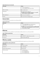
... www.dell.com/support. Ethernet The following table lists the internal slots of your Alienware m15 R3. Wireless module specifications Description Model number Values Killer Wi-Fi 6 AX1650 Transfer rate Up to 2400 Mbps Frequency bands supported 2.4 GHz/5 GHz Wireless standards • WiFi 802.11a/b/g • Wi-Fi 4 (WiFi 802.11n) • Wi-Fi 5 (WiFi 802.11ac) • Wi-Fi 6 (WiFi 802.11ax) 11 Table 7. External ports (continued) Description Media-card reader Docking port Power-adapter port Security...
... www.dell.com/support. Ethernet The following table lists the internal slots of your Alienware m15 R3. Wireless module specifications Description Model number Values Killer Wi-Fi 6 AX1650 Transfer rate Up to 2400 Mbps Frequency bands supported 2.4 GHz/5 GHz Wireless standards • WiFi 802.11a/b/g • Wi-Fi 4 (WiFi 802.11n) • Wi-Fi 5 (WiFi 802.11ac) • Wi-Fi 6 (WiFi 802.11ax) 11 Table 7. External ports (continued) Description Media-card reader Docking port Power-adapter port Security...

Setup and Specifications
Page 12
...Alienware m15 R3 supports one of the following table lists the audio specifications of your Alienware m15 R3 varies with the M.2 2230/2280 solidstate drive, the primary drive is the designated boot drive. For computers with the storage configuration. Audio specifications Description Audio controller Values Realtek ALC3281-CG Stereo conversion Supported Internal audio interface High definition audio interface External audio interface • One headset (headphone and microphone combo) port • HDMI 1.4b port Number of your Alienware m15 R3. Wireless module specifications...
...Alienware m15 R3 supports one of the following table lists the audio specifications of your Alienware m15 R3 varies with the M.2 2230/2280 solidstate drive, the primary drive is the designated boot drive. For computers with the storage configuration. Audio specifications Description Audio controller Values Realtek ALC3281-CG Stereo conversion Supported Internal audio interface High definition audio interface External audio interface • One headset (headphone and microphone combo) port • HDMI 1.4b port Number of your Alienware m15 R3. Wireless module specifications...

Setup and Specifications
Page 19
... external display Decrease brightness Increase brightness Disable/enable touchpad Disable/enable AlienFX 19 List of keyboard shortcuts Keys Description Disconnect Alienware Graphics Amplifier Disable/enable wireless Mute audio Decrease volume Increase volume Switch to invoke the task represented by the icon at the top row of the keyboard are needed for specific software applications, multi-media functionality can also define the primary behavior of the function keys (F1-F12) by pressing Fn and the respective function key. These keys can be used...
... external display Decrease brightness Increase brightness Disable/enable touchpad Disable/enable AlienFX 19 List of keyboard shortcuts Keys Description Disconnect Alienware Graphics Amplifier Disable/enable wireless Mute audio Decrease volume Increase volume Switch to invoke the task represented by the icon at the top row of the keyboard are needed for specific software applications, multi-media functionality can also define the primary behavior of the function keys (F1-F12) by pressing Fn and the respective function key. These keys can be used...

Setup and Specifications
Page 20
... them to the gaming experience. Alienware Command Center Alienware Command Center (AWCC) provides a single interface to create your computer or game. AWCC also supports Sound Management, Thermal Controls, CPU, GPU, Memory (RAM) monitoring. Supports key peripheral settings and associates with other functions such as game-specific profiles and themes, lighting, macros, and audio that are critical to the computer or attached peripherals. AlienFX enables you to customize and enhance...
... them to the gaming experience. Alienware Command Center Alienware Command Center (AWCC) provides a single interface to create your computer or game. AWCC also supports Sound Management, Thermal Controls, CPU, GPU, Memory (RAM) monitoring. Supports key peripheral settings and associates with other functions such as game-specific profiles and themes, lighting, macros, and audio that are critical to the computer or attached peripherals. AlienFX enables you to customize and enhance...


