
Owners Manual
Page 3
......10 Battery charge and status light ...11 Chapter 2: Set up your Alienware m16 R2 12 Chapter 3: Specifications of Alienware m16 R2 13 Dimensions and weight...13 Processor...13 Chipset...13 Operating system...14 Memory...14 External ports...14 Internal slots...15 Ethernet...15 Wireless module...15 Audio...16 Storage...16 Media-card reader...17 Keyboard...17 Keyboard shortcuts...18 Camera...19 Touchpad...20 Power adapter...20 Battery...21 GPU-Integrated...22 GPU-Discrete...22 External display support...22 Display...22 Operating and storage environment...23 Dell support...
......10 Battery charge and status light ...11 Chapter 2: Set up your Alienware m16 R2 12 Chapter 3: Specifications of Alienware m16 R2 13 Dimensions and weight...13 Processor...13 Chipset...13 Operating system...14 Memory...14 External ports...14 Internal slots...15 Ethernet...15 Wireless module...15 Audio...16 Storage...16 Media-card reader...17 Keyboard...17 Keyboard shortcuts...18 Camera...19 Touchpad...20 Power adapter...20 Battery...21 GPU-Integrated...22 GPU-Discrete...22 External display support...22 Display...22 Operating and storage environment...23 Dell support...
Owners Manual
Page 4
...Battery cable...47 Removing the battery cable...47 Installing the battery cable...48 Rear I/O cover...49 Removing the rear I/O cover...49 Installing the rear I/O cover...50 Fan and heat-sink assembly...52 Removing the fan and heat-sink assembly...52 Installing the fan and heat-sink assembly...53 Speakers...54 Removing the speakers...54 Installing the speakers...55 Power-adapter port...56 Removing the power-adapter port...56 Installing the power-adapter port...57 Touchpad...59 Removing the touchpad...59 Installing the touchpad...60 Keyboard-controller board...61 Removing the keyboard-controller...
...Battery cable...47 Removing the battery cable...47 Installing the battery cable...48 Rear I/O cover...49 Removing the rear I/O cover...49 Installing the rear I/O cover...50 Fan and heat-sink assembly...52 Removing the fan and heat-sink assembly...52 Installing the fan and heat-sink assembly...53 Speakers...54 Removing the speakers...54 Installing the speakers...55 Power-adapter port...56 Removing the power-adapter port...56 Installing the power-adapter port...57 Touchpad...59 Removing the touchpad...59 Installing the touchpad...60 Keyboard-controller board...61 Removing the keyboard-controller...
Owners Manual
Page 5
... audio board...79 Installing the audio board...80 Power button...81 Removing the power button...81 Installing the power button...82 Palm rest and keyboard assembly...83 Removing the palm rest and keyboard assembly...83 Installing the palm rest and keyboard assembly...84 Chapter 8: Software...86 Operating system...86 Drivers and downloads...86 Chapter 9: BIOS Setup...87 Entering BIOS setup program...87 Navigation keys...87 F12 One Time Boot menu...87 System setup options...88 Updating the BIOS...102 Updating the BIOS in Windows...102 Updating the BIOS using the USB drive...
... audio board...79 Installing the audio board...80 Power button...81 Removing the power button...81 Installing the power button...82 Palm rest and keyboard assembly...83 Removing the palm rest and keyboard assembly...83 Installing the palm rest and keyboard assembly...84 Chapter 8: Software...86 Operating system...86 Drivers and downloads...86 Chapter 9: BIOS Setup...87 Entering BIOS setup program...87 Navigation keys...87 F12 One Time Boot menu...87 System setup options...88 Updating the BIOS...102 Updating the BIOS in Windows...102 Updating the BIOS using the USB drive...
Owners Manual
Page 9
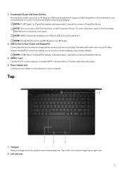
... required to connect an external display using a display adapter. 1. Supports USB4, DisplayPort 1.4, Thunderbolt 4, and also enables you to connect a DisplayPort device. Supports DisplayPort 1.4 and also enables you to connect to DisplayPort adapter (sold separately) is backward compatible with DisplayPort Connect devices such as external storage devices, printers, and external displays. Provides video and audio output. 4. Tap to left-click and two fingers tap to the Thunderbolt 4 ports. NOTE: A USB Type-C to an external display using a display adapter. Top 1. Touchpad Move...
... required to connect an external display using a display adapter. 1. Supports USB4, DisplayPort 1.4, Thunderbolt 4, and also enables you to connect a DisplayPort device. Supports DisplayPort 1.4 and also enables you to connect to DisplayPort adapter (sold separately) is backward compatible with DisplayPort Connect devices such as external storage devices, printers, and external displays. Provides video and audio output. 4. Tap to left-click and two fingers tap to the Thunderbolt 4 ports. NOTE: A USB Type-C to an external display using a display adapter. Top 1. Touchpad Move...
Owners Manual
Page 15
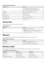
... 4 port with Power Delivery One universal audio jack (RCA, 3.5 mm) One HDMI 2.1 port One microSD-card slot One 7.40 mm x 5.10 mm DC-in the Knowledge Base Resource at www.dell.com/support. Ethernet The following table lists the wired Ethernet Local Area Network (LAN) specifications of M.2 cards, search in Not supported Internal slots The following table lists the Wireless Local Area Network (WLAN) modules that are supported on your Alienware m16 R2. Ethernet specifications Description Model number Values...
... 4 port with Power Delivery One universal audio jack (RCA, 3.5 mm) One HDMI 2.1 port One microSD-card slot One 7.40 mm x 5.10 mm DC-in the Knowledge Base Resource at www.dell.com/support. Ethernet The following table lists the wired Ethernet Local Area Network (LAN) specifications of M.2 cards, search in Not supported Internal slots The following table lists the Wireless Local Area Network (WLAN) modules that are supported on your Alienware m16 R2. Ethernet specifications Description Model number Values...
Owners Manual
Page 18
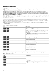
... for specific software applications, multimedia functionality can be used for multimedia control that is shown on the upper part of the key refers to perform multiple actions with pre-programmable macro keys that are needed for the macro keys on the configuration of the keyboard are function keys for shortcuts remain the same across all language configurations. Performance settings change to the table below). Increase display brightness. Disable or enable touchpad. The...
... for specific software applications, multimedia functionality can be used for multimedia control that is shown on the upper part of the key refers to perform multiple actions with pre-programmable macro keys that are needed for the macro keys on the configuration of the keyboard are function keys for shortcuts remain the same across all language configurations. Performance settings change to the table below). Increase display brightness. Disable or enable touchpad. The...
Owners Manual
Page 25
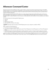
... adjust game-specific Power Management, Sound Management, and Thermal Management features. ● Peripheral Management: Peripheral Management enables peripherals to your computer or game. For more information about the location of AlienFX lighting zones on the back of the display NOTE: Information about AWCC, see the Alienware Command Center Online Help or search in the Knowledge Base Resource at www.dell.com/support. 25 AlienFX enables you to create...
... adjust game-specific Power Management, Sound Management, and Thermal Management features. ● Peripheral Management: Peripheral Management enables peripherals to your computer or game. For more information about the location of AlienFX lighting zones on the back of the display NOTE: Information about AWCC, see the Alienware Command Center Online Help or search in the Knowledge Base Resource at www.dell.com/support. 25 AlienFX enables you to create...
Owners Manual
Page 26
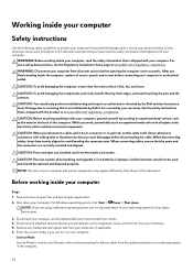
.... Enter the service mode, if you work surface is not covered by their electrical outlets. 4. Damage due to avoid bending the connector pins. CAUTION: When you have connectors with locking tabs or thumbscrews that is shipped with your computer. When disconnecting cables, keep them by your warranty. Swollen batteries should not be replaced and disposed properly. For Windows operating system, click Start > Power...
.... Enter the service mode, if you work surface is not covered by their electrical outlets. 4. Damage due to avoid bending the connector pins. CAUTION: When you have connectors with locking tabs or thumbscrews that is shipped with your computer. When disconnecting cables, keep them by your warranty. Swollen batteries should not be replaced and disposed properly. For Windows operating system, click Start > Power...
Owners Manual
Page 27
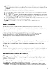
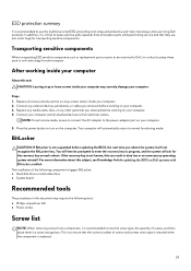
.... ● Use an ESD field service kit when working inside any notebook to avoid electrostatic discharge (ESD) damage. ● After removing any key to remove the AC adapter appears on the screen. Catastrophic failures represent approximately 20 percent of device functionality. The damage causes an immediate and complete loss of ESD-related failures. An example of ESD damage are powered while turned off...
.... ● Use an ESD field service kit when working inside any notebook to avoid electrostatic discharge (ESD) damage. ● After removing any key to remove the AC adapter appears on the screen. Catastrophic failures represent approximately 20 percent of device functionality. The damage causes an immediate and complete loss of ESD-related failures. An example of ESD damage are powered while turned off...
Owners Manual
Page 29
... the power button to normal functioning mode. The installation of the following tools: ● Phillips screwdriver #0 ● Plastic scribe Screw list NOTE: When removing screws from all screws and ensure that you removed before working on your computer About this can result in this subject, see Knowledge Article: updating the BIOS on your computer. Replace any media cards, discs, or any external devices, peripherals, or cables you reboot the...
... the power button to normal functioning mode. The installation of the following tools: ● Phillips screwdriver #0 ● Plastic scribe Screw list NOTE: When removing screws from all screws and ensure that you removed before working on your computer About this can result in this subject, see Knowledge Article: updating the BIOS on your computer. Replace any media cards, discs, or any external devices, peripherals, or cables you reboot the...
Owners Manual
Page 46
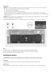
... battery to enter the BIOS and configure the date and time. NOTE: Removing the battery resets the BIOS setup menu settings to the palm rest and keyboard assembly. 3. The following image(s) indicate the location of the battery and provides a visual representation of the removal procedure. It is displayed prompting you are replacing a component, remove the existing component before removing the battery. About this task NOTE: This computer is intended for authorized service...
... battery to enter the BIOS and configure the date and time. NOTE: Removing the battery resets the BIOS setup menu settings to the palm rest and keyboard assembly. 3. The following image(s) indicate the location of the battery and provides a visual representation of the removal procedure. It is displayed prompting you are replacing a component, remove the existing component before removing the battery. About this task NOTE: This computer is intended for authorized service...
Owners Manual
Page 91
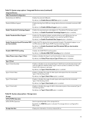
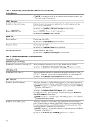
...32. System setup options-Storage menu Storage SATA/NVMe Operation SATA/NVMe Operation Sets the operating mode of various onboard drives. 91 By default, the Enable External USB Ports option is enabled. By default, the Enable Thunderbolt Technology Support option is enabled. By default, the Enable Thunderbolt (and PCIe behind TBT) Enables the PCIe devices that are connected through a Thunderbolt adapter to run pre-boot modules the PCIe devices UEFI Option ROM (if present) during BIOS Preboot. Type-C Dock Type-C Dock Override Enables or disables to use connected Type-C Dell Dock...
...32. System setup options-Storage menu Storage SATA/NVMe Operation SATA/NVMe Operation Sets the operating mode of various onboard drives. 91 By default, the Enable External USB Ports option is enabled. By default, the Enable Thunderbolt Technology Support option is enabled. By default, the Enable Thunderbolt (and PCIe behind TBT) Enables the PCIe devices that are connected through a Thunderbolt adapter to run pre-boot modules the PCIe devices UEFI Option ROM (if present) during BIOS Preboot. Type-C Dock Type-C Dock Override Enables or disables to use connected Type-C Dell Dock...
Owners Manual
Page 93
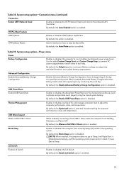
..., Advanced Battery Charged maximizes battery health while still supporting heavy use during peak power usage hours. By default, the Enable USB PowerShare option is enabled. Table 34. System setup options-Connection menu (continued) Connection Enable UEFI Network Stack Enables or disables the UEFI Network Stack and controls the onboard LAN Controller. HTTP(s) Boot Feature HTTP(s) Boot Enables or disables HTTP(s) Boot capabilities. HTTP(s) Boot Modes Sets the method on Dell USB-C Dock When enabled, connecting a Dell USB-C Dock wakes the computer from entering Sleep (S3) mode in...
..., Advanced Battery Charged maximizes battery health while still supporting heavy use during peak power usage hours. By default, the Enable USB PowerShare option is enabled. Table 34. System setup options-Connection menu (continued) Connection Enable UEFI Network Stack Enables or disables the UEFI Network Stack and controls the onboard LAN Controller. HTTP(s) Boot Feature HTTP(s) Boot Enables or disables HTTP(s) Boot capabilities. HTTP(s) Boot Modes Sets the method on Dell USB-C Dock When enabled, connecting a Dell USB-C Dock wakes the computer from entering Sleep (S3) mode in...
Owners Manual
Page 94
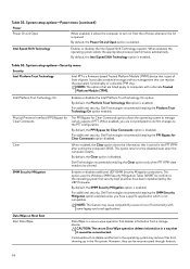
.... It provides credential storage and key management that it allows the computer to turn on Next Boot Start Data Wipe Data Wipe is a secure wipe operation that security best practices have a specific application which is enabled. By default, the PPI Bypass for Clear Commands option disabled. Dell Technologies recommends enabling the Clear option only when PTT fTPM data needs to the PTT configuration. CAUTION: The secure Data Wipe...
.... It provides credential storage and key management that it allows the computer to turn on Next Boot Start Data Wipe Data Wipe is a secure wipe operation that security best practices have a specific application which is enabled. By default, the PPI Bypass for Clear Commands option disabled. Dell Technologies recommends enabling the Clear option only when PTT fTPM data needs to the PTT configuration. CAUTION: The secure Data Wipe...
Owners Manual
Page 97
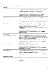
... Setup Changes option is disabled. By default, the Admin Setup Lockout option is disabled. Password Bypass The Password Bypass option allows the computer to set ). If the computer has already booted to the operating system, it requires passwords to include at least eight characters. This gives an administrator control over the BIOS settings but enables an end user to configure the wireless devices without first entering the administrator password (if set or change the computer or hard drive passwords without entering...
... Setup Changes option is disabled. By default, the Admin Setup Lockout option is disabled. Password Bypass The Password Bypass option allows the computer to set ). If the computer has already booted to the operating system, it requires passwords to include at least eight characters. This gives an administrator control over the BIOS settings but enables an end user to configure the wireless devices without first entering the administrator password (if set or change the computer or hard drive passwords without entering...
Owners Manual
Page 98
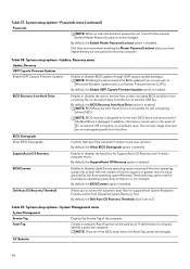
... work in the BIOS setup menu, the Asset Tag cannot be changed . Dell does not recommend enabling the Master Password Lockout unless you to recover from certain corrupted BIOS conditions from Hard Drive option is not installed. Table 38. By default, the Dell Auto OS Recovery Threshold value is designed to 2. NOTE: Once set , it must exist on an unencrypted partition on the user primary hard drive or an external USB key. BIOS Recovery from Hard Drive Enables or disables the user...
... work in the BIOS setup menu, the Asset Tag cannot be changed . Dell does not recommend enabling the Master Password Lockout unless you to recover from certain corrupted BIOS conditions from Hard Drive option is not installed. Table 38. By default, the Dell Auto OS Recovery Threshold value is designed to 2. NOTE: Once set , it must exist on an unencrypted partition on the user primary hard drive or an external USB key. BIOS Recovery from Hard Drive Enables or disables the user...
Owners Manual
Page 100
... boot when the USB-C adapters with less power capacity are detected. For operating systems that support DMA protection, this setting indicates to control the Pre-Boot DMA protection for memory map I /O option is an Intel method that the BIOS supports the feature. System setup options-Pre-boot Behavior menu (continued) Preboot Behavior NOTE: Errors deemed critical to control the Kernel DMA protection for Direct I /O. By default, the 0 seconds option is enabled. Early Logo Display Display...
... boot when the USB-C adapters with less power capacity are detected. For operating systems that support DMA protection, this setting indicates to control the Pre-Boot DMA protection for memory map I /O option is an Intel method that the BIOS supports the feature. System setup options-Pre-boot Behavior menu (continued) Preboot Behavior NOTE: Errors deemed critical to control the Kernel DMA protection for Direct I /O. By default, the 0 seconds option is enabled. Early Logo Display Display...
Owners Manual
Page 103
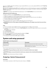
... a USB port of the Dell computers built after the BIOS update is completed. Click Update BIOS. System and setup password Table 45. The computer restarts to access the One Time Boot Menu, select BIOS Update using a bootable USB drive or you can assign a new System or Admin Password only when the status is in Not Set. 103 You can run the BIOS update file from Windows using the mouse or arrow keys then press Enter. Password that is connected...
... a USB port of the Dell computers built after the BIOS update is completed. Click Update BIOS. System and setup password Table 45. The computer restarts to access the One Time Boot Menu, select BIOS Update using a bootable USB drive or you can assign a new System or Admin Password only when the status is in Not Set. 103 You can run the BIOS update file from Windows using the mouse or arrow keys then press Enter. Password that is connected...
Owners Manual
Page 107
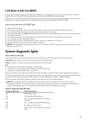
... the video card (GPU) and computer settings. Power off , indicating no dust particles on battery, and the battery has more than 5% charge. The power and battery-status light may also blink red or blue according to confirm functionality of the screen). 4. Off: ● Power adapter is connected, and the battery is fully charged. ● Computer is detected. LCD Built-in Self-Test (BIST) Dell laptops have a built-in hinge cable tripped OCP2 (display) 1,5 EC...
... the video card (GPU) and computer settings. Power off , indicating no dust particles on battery, and the battery has more than 5% charge. The power and battery-status light may also blink red or blue according to confirm functionality of the screen). 4. Off: ● Power adapter is connected, and the battery is fully charged. ● Computer is detected. LCD Built-in Self-Test (BIST) Dell laptops have a built-in hinge cable tripped OCP2 (display) 1,5 EC...
Owners Manual
Page 109
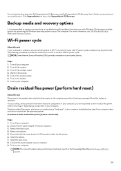
... flea power, also known as a performing a "hard reset", is recommended to create a recovery drive to Wi-Fi connectivity issues a Wi-Fi power cycle procedure may occur with Windows. Remove the battery. 5. For more information about the Dell SupportAssist OS Recovery, see Dell Windows Backup Media and Recovery Options. Steps 1. Turn on or boot into the operating system. Press and hold the power button for 20 seconds to drain the flea power. 6. Turn off and the battery is...
... flea power, also known as a performing a "hard reset", is recommended to create a recovery drive to Wi-Fi connectivity issues a Wi-Fi power cycle procedure may occur with Windows. Remove the battery. 5. For more information about the Dell SupportAssist OS Recovery, see Dell Windows Backup Media and Recovery Options. Steps 1. Turn on or boot into the operating system. Press and hold the power button for 20 seconds to drain the flea power. 6. Turn off and the battery is...


