
Owner's Manual
Page 5
... 46 Postrequisites 46 Removing the Status-Light Board 47 Prerequisites 47 Procedure 48 Replacing the Status-Light Board 49 Procedure 49 Postrequisites 49 Removing the Keyboard 50 Prerequisites 50 Procedure 51 Replacing the Keyboard 53 Procedure 53 Postrequisites 53 Contents | 5
... 46 Postrequisites 46 Removing the Status-Light Board 47 Prerequisites 47 Procedure 48 Replacing the Status-Light Board 49 Procedure 49 Postrequisites 49 Removing the Keyboard 50 Prerequisites 50 Procedure 51 Replacing the Keyboard 53 Procedure 53 Postrequisites 53 Contents | 5
Owner's Manual
Page 6
... Prerequisites 54 Procedure 54 Replacing the Macro Keyboard 55 Procedure 55 Postrequisites 55 Removing the Display Assembly 56 Prerequisites 56 Procedure 56 Replacing the Display Assembly 60 Procedure 60 Postrequisites 60 Removing the ...
... Prerequisites 54 Procedure 54 Replacing the Macro Keyboard 55 Procedure 55 Postrequisites 55 Removing the Display Assembly 56 Prerequisites 56 Procedure 56 Replacing the Display Assembly 60 Procedure 60 Postrequisites 60 Removing the ...
Owner's Manual
Page 18
... memory module connectors. You can access connectors DIMM3 and DIMM4 by removing the keyboard. See "Removing the Base Cover" on page 16. 18 | Removing the Memory Module(s) You can access connectors DIMM1 and DIMM2 by removing the base cover at dell.com/regulatory_compliance. For additional safety best practices information, see the Regulatory Compliance...
... memory module connectors. You can access connectors DIMM3 and DIMM4 by removing the keyboard. See "Removing the Base Cover" on page 16. 18 | Removing the Memory Module(s) You can access connectors DIMM1 and DIMM2 by removing the base cover at dell.com/regulatory_compliance. For additional safety best practices information, see the Regulatory Compliance...

Owner's Manual
Page 40
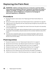
Procedure 1 Lift the connector latches and pull the pull-tabs to disconnect the media-card reader cable and keyboard cable from the connectors on the palm-rest assembly. 2 Lift the connector latches and pull the pull-tabs to disconnect the macro-keyboard cable and macro-keyboard backlight cable from the connectors on the system board. 3 Remove the screws that secure the palm-rest assembly to the computer base. 1 2 3 5 4 1 screws (9) 3 macro-keyboard backlight cable 5 media-card reader cable 2 macro-keyboard cable 4 keyboard cable 40 | Removing the Palm Rest
Procedure 1 Lift the connector latches and pull the pull-tabs to disconnect the media-card reader cable and keyboard cable from the connectors on the palm-rest assembly. 2 Lift the connector latches and pull the pull-tabs to disconnect the macro-keyboard cable and macro-keyboard backlight cable from the connectors on the system board. 3 Remove the screws that secure the palm-rest assembly to the computer base. 1 2 3 5 4 1 screws (9) 3 macro-keyboard backlight cable 5 media-card reader cable 2 macro-keyboard cable 4 keyboard cable 40 | Removing the Palm Rest
Owner's Manual
Page 42
... on the palm-rest assembly, and press down on the connector latches to secure the cables. 6 Slide the macro-keyboard cable and macro-keyboard backlight cable into the respective connectors on the system board, and press down on the connector latches to secure the cables... 17. 5 Replace the base cover. Postrequisites 1 Replace the optical drive. For additional safety best practices information, see the Regulatory Compliance Homepage at dell.com/regulatory_compliance. See "Replacing the Battery Pack" on page 46. 2 Replace the status-light board. See "Replacing the Status-Light Board" on...
... on the palm-rest assembly, and press down on the connector latches to secure the cables. 6 Slide the macro-keyboard cable and macro-keyboard backlight cable into the respective connectors on the system board, and press down on the connector latches to secure the cables... 17. 5 Replace the base cover. Postrequisites 1 Replace the optical drive. For additional safety best practices information, see the Regulatory Compliance Homepage at dell.com/regulatory_compliance. See "Replacing the Battery Pack" on page 46. 2 Replace the status-light board. See "Replacing the Status-Light Board" on...
Owner's Manual
Page 50
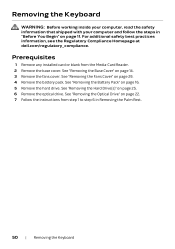
...your computer, read the safety information that shipped with your computer and follow the steps in Removing the Palm Rest. 50 | Removing the Keyboard See "Removing the Base Cover" on page 11. See "Removing the Battery Pack" on page 25. 6 Remove the optical drive. For... additional safety best practices information, see the Regulatory Compliance Homepage at dell.com/regulatory_compliance. See "Removing the Hard Drive(s)" on page 16. 5 Remove the hard drive. See "Removing the Optical Drive" on page 29....
...your computer, read the safety information that shipped with your computer and follow the steps in Removing the Palm Rest. 50 | Removing the Keyboard See "Removing the Base Cover" on page 11. See "Removing the Battery Pack" on page 25. 6 Remove the optical drive. For... additional safety best practices information, see the Regulatory Compliance Homepage at dell.com/regulatory_compliance. See "Removing the Hard Drive(s)" on page 16. 5 Remove the hard drive. See "Removing the Optical Drive" on page 29....

Owner's Manual
Page 51
... do so could result in scratching the display panel.Lift the connector latches and pull the pull-tabs to the keyboard. CAUTION: Be extremely careful when removing and handling the keyboard. CAUTION: The keycaps on the keyboard are fragile, easily dislodged, and time-consuming to replace. Be careful when removing and handling the...
... do so could result in scratching the display panel.Lift the connector latches and pull the pull-tabs to the keyboard. CAUTION: Be extremely careful when removing and handling the keyboard. CAUTION: The keycaps on the keyboard are fragile, easily dislodged, and time-consuming to replace. Be careful when removing and handling the...

Owner's Manual
Page 52
3 Lift the connector latch and pull the pull-tab to disconnect the keyboard cable from the respective connector. 4 Remove the screws that secure the keyboard to the palm-rest assembly. 1 2 1 screws (2) 2 keyboard cable 5 Lift the keyboard off the palm-rest assembly. 52 | Removing the Keyboard
3 Lift the connector latch and pull the pull-tab to disconnect the keyboard cable from the respective connector. 4 Remove the screws that secure the keyboard to the palm-rest assembly. 1 2 1 screws (2) 2 keyboard cable 5 Lift the keyboard off the palm-rest assembly. 52 | Removing the Keyboard
Owner's Manual
Page 53
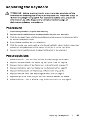
...safety best practices information, see the Regulatory Compliance Homepage at dell.com/regulatory_compliance. Procedure 1 Place the keyboard on the palm-rest assembly. 2 Replace the screws that secure the keyboard to the palm-rest assembly. 3 Slide the keyboard cable into their respective connectors and press down on the ... Media-Card Reader. 8 Follow the instructions in "After Working Inside Your Computer" on page 28. 4 Replace the battery pack. Replacing the Keyboard | 53 See "Replacing the Hard Drive(s)" on page 13. See "Replacing the Base Cover" on page 15. 7 Replace any card or...
...safety best practices information, see the Regulatory Compliance Homepage at dell.com/regulatory_compliance. Procedure 1 Place the keyboard on the palm-rest assembly. 2 Replace the screws that secure the keyboard to the palm-rest assembly. 3 Slide the keyboard cable into their respective connectors and press down on the ... Media-Card Reader. 8 Follow the instructions in "After Working Inside Your Computer" on page 28. 4 Replace the battery pack. Replacing the Keyboard | 53 See "Replacing the Hard Drive(s)" on page 13. See "Replacing the Base Cover" on page 15. 7 Replace any card or...
Owner's Manual
Page 54
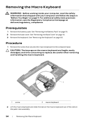
... 3 Remove the keyboard. See "Removing the Keyboard" on page 11. CAUTION: The keycaps on the palm-rest assembly. 54 | Removing the Macro Keyboard Removing the Macro Keyboard WARNING: Before working ...inside your computer, read the safety information that secures the macro keyboard to replace. Procedure 1 ... handling the macro keyboard. 1 2 1 screw 2 macro keyboard 2 Lift the macro keyboard and slide the tab on the macro-keyboard out of the slot on the macro keyboard are fragile, easily...
... 3 Remove the keyboard. See "Removing the Keyboard" on page 11. CAUTION: The keycaps on the palm-rest assembly. 54 | Removing the Macro Keyboard Removing the Macro Keyboard WARNING: Before working ...inside your computer, read the safety information that secures the macro keyboard to replace. Procedure 1 ... handling the macro keyboard. 1 2 1 screw 2 macro keyboard 2 Lift the macro keyboard and slide the tab on the macro-keyboard out of the slot on the macro keyboard are fragile, easily...
Owner's Manual
Page 55
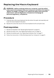
... place. 2 Replace the screw that shipped with your computer, read the safety information that secures the macro keyboard to the computer base. See "Replacing the Battery Pack" on page 17. 4 Follow the instructions in "Before You Begin" on page... 11. For additional safety best practices information, see the Regulatory Compliance Homepage at dell.com/regulatory_compliance. See "Replacing the Keyboard" on page 53. 2 Replace the base cover. Replacing the Macro Keyboard | 55 Replacing the Macro Keyboard WARNING: Before working inside your computer and follow the steps in "After Working ...
... place. 2 Replace the screw that shipped with your computer, read the safety information that secures the macro keyboard to the computer base. See "Replacing the Battery Pack" on page 17. 4 Follow the instructions in "Before You Begin" on page... 11. For additional safety best practices information, see the Regulatory Compliance Homepage at dell.com/regulatory_compliance. See "Replacing the Keyboard" on page 53. 2 Replace the base cover. Replacing the Macro Keyboard | 55 Replacing the Macro Keyboard WARNING: Before working inside your computer and follow the steps in "After Working ...
Owner's Manual
Page 109
... appears, continue to wait until you must watch for it is lost. This prompt can make your computer. 2 During POST, when the ALIENWARE logo is displayed, watch for the F2 prompt to appear and then press immediately. System Setup | 109 Then, turn off your computer, ...Unless you change the settings for future reference. If you write down the system setup screen information for this keystroke is recommended that the keyboard has initialized. NOTE: The F2 prompt indicates that you press before the F2 prompt, this program. System Setup Overview Use the system ...
... appears, continue to wait until you must watch for it is lost. This prompt can make your computer. 2 During POST, when the ALIENWARE logo is displayed, watch for the F2 prompt to appear and then press immediately. System Setup | 109 Then, turn off your computer, ...Unless you change the settings for future reference. If you write down the system setup screen information for this keystroke is recommended that the keyboard has initialized. NOTE: The F2 prompt indicates that you press before the F2 prompt, this program. System Setup Overview Use the system ...
Owner's Manual
Page 118
...Sequence for the Current Boot You can appear very quickly, so you see the operating system's desktop. NOTE: The F2 prompt indicates that the keyboard has initialized. and down your current boot sequence in the lower-right corner of the device. 118 | System Setup The previous boot sequence ...priority of the screen, press . NOTE: Write down -arrow keys to select LEGACY BOOT or UEFI BOOT. 4 Press plus (+) or minus (-) to run Dell Diagnostics from a USB device, connect the USB device to a USB memory key, highlight USB Storage Device and press . For example, if you want to...
...Sequence for the Current Boot You can appear very quickly, so you see the operating system's desktop. NOTE: The F2 prompt indicates that the keyboard has initialized. and down your current boot sequence in the lower-right corner of the device. 118 | System Setup The previous boot sequence ...priority of the screen, press . NOTE: Write down -arrow keys to select LEGACY BOOT or UEFI BOOT. 4 Press plus (+) or minus (-) to run Dell Diagnostics from a USB device, connect the USB device to a USB memory key, highlight USB Storage Device and press . For example, if you want to...
Quick Start Guide
Page 1
... AlienHead logo are trademarks or registered trademarks of Dell Inc. 2013 - 04 Regulatory model: P19E | Type: P19E001 Computer model: Alienware 18 R1 更多信息 FAQ dell.com/Alienware dell.com/ContactDell © 2013 Dell Inc. USB 3.0 ポート (2) 21. ミニ DisplayPort 22. Wireless-status light 8 8 9. Backlit keyboard 14 15 16. Left digital-array microphone...
... AlienHead logo are trademarks or registered trademarks of Dell Inc. 2013 - 04 Regulatory model: P19E | Type: P19E001 Computer model: Alienware 18 R1 更多信息 FAQ dell.com/Alienware dell.com/ContactDell © 2013 Dell Inc. USB 3.0 ポート (2) 21. ミニ DisplayPort 22. Wireless-status light 8 8 9. Backlit keyboard 14 15 16. Left digital-array microphone...


