
Owner's Manual
Page 3
... Connected Devices 11 Safety Instructions 12 Recommended Tools 12 After Working Inside Your Computer 13 Removing the Base Cover 14 Procedure 14 Replacing the Base Cover 15 Procedure 15 Postrequisites 15 Removing the Battery Pack 16 Procedure 16 Replacing the Battery Pack 17 Procedure 17 Postrequisites 17 Removing the Memory Module(s 18 Prerequisites 18 Procedure 19 Replacing the Memory Module(s 20 Procedure 20 Postrequisites 21 Removing the Optical Drive 22 Prerequisites 22 Replacing...
... Connected Devices 11 Safety Instructions 12 Recommended Tools 12 After Working Inside Your Computer 13 Removing the Base Cover 14 Procedure 14 Replacing the Base Cover 15 Procedure 15 Postrequisites 15 Removing the Battery Pack 16 Procedure 16 Replacing the Battery Pack 17 Procedure 17 Postrequisites 17 Removing the Memory Module(s 18 Prerequisites 18 Procedure 19 Replacing the Memory Module(s 20 Procedure 20 Postrequisites 21 Removing the Optical Drive 22 Prerequisites 22 Replacing...
Owner's Manual
Page 6
... 54 Replacing the Macro Keyboard 55 Procedure 55 Postrequisites 55 Removing the Display Assembly 56 Prerequisites 56 Procedure 56 Replacing the Display Assembly 60 Procedure 60 Postrequisites 60 Removing the Camera Module 61 Prerequisites 61 Procedure 62 Replacing the Camera Module 63 Procedure 63 Postrequisites 63 Removing the Display Bezel 64 Prerequisites 64 Procedure 64 Replacing the Display Bezel 65 Procedure 65 Postrequisites 65 Removing the Display Hinges...
... 54 Replacing the Macro Keyboard 55 Procedure 55 Postrequisites 55 Removing the Display Assembly 56 Prerequisites 56 Procedure 56 Replacing the Display Assembly 60 Procedure 60 Postrequisites 60 Removing the Camera Module 61 Prerequisites 61 Procedure 62 Replacing the Camera Module 63 Procedure 63 Postrequisites 63 Removing the Display Bezel 64 Prerequisites 64 Procedure 64 Replacing the Display Bezel 65 Procedure 65 Postrequisites 65 Removing the Display Hinges...
Owner's Manual
Page 8
Removing the Sound Board 85 Prerequisites 85 Procedure 86 Replacing the Sound Board 87 Procedure 87 Postrequisites 87 Removing the Video-Card Heat-Sink(s 88 Prerequisites 88 Procedure 88 Replacing the Video-Card Heat-Sink(s 90 Procedure 90 Postrequisites 90 Removing the Video Card(s 91 Prerequisites 91 Procedure 91 Replacing the Video Card(s 93 Procedure 93 Postrequisites 93 Removing the Processor Heat-Sink 94 Prerequisites 94 Procedure 94 Replacing the Processor...
Removing the Sound Board 85 Prerequisites 85 Procedure 86 Replacing the Sound Board 87 Procedure 87 Postrequisites 87 Removing the Video-Card Heat-Sink(s 88 Prerequisites 88 Procedure 88 Replacing the Video-Card Heat-Sink(s 90 Procedure 90 Postrequisites 90 Removing the Video Card(s 91 Prerequisites 91 Procedure 91 Replacing the Video Card(s 93 Procedure 93 Postrequisites 93 Removing the Processor Heat-Sink 94 Prerequisites 94 Procedure 94 Replacing the Processor...
Owner's Manual
Page 12
...by their edges and avoid touching pins and contacts. See the safety instructions for complete information about safety precautions, working inside the computer. CAUTION: Only a certified service technician is flat and clean. Safety Instructions Use the following tools: &#...cards, handle them evenly aligned to protect your computer from the network device. CAUTION: When you finish working inside the computer, replace all power sources before disconnecting the cable. WARNING: Disconnect all covers, panels, and screws before connecting to remove the computer cover and access...
...by their edges and avoid touching pins and contacts. See the safety instructions for complete information about safety precautions, working inside the computer. CAUTION: Only a certified service technician is flat and clean. Safety Instructions Use the following tools: &#...cards, handle them evenly aligned to protect your computer from the network device. CAUTION: When you finish working inside the computer, replace all power sources before disconnecting the cable. WARNING: Disconnect all covers, panels, and screws before connecting to remove the computer cover and access...
Owner's Manual
Page 13
...: Before turning on your computer • Connect your computer. After Working Inside Your Computer | 13 After Working Inside Your Computer After you removed before working on your computer, replace all screws and ensure that no stray screws remain inside your computer • Connect any external devices, cables, cards, and any other part(s) you complete the replacement procedures, ensure the following: • Replace all attached devices to...
...: Before turning on your computer • Connect your computer. After Working Inside Your Computer | 13 After Working Inside Your Computer After you removed before working on your computer, replace all screws and ensure that no stray screws remain inside your computer • Connect any external devices, cables, cards, and any other part(s) you complete the replacement procedures, ensure the following: • Replace all attached devices to...
Owner's Manual
Page 18
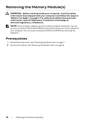
... steps in "Before You Begin" on page 7. 2 Remove the battery. Removing the Memory Module(s) WARNING: Before working inside your computer, read the safety information that shipped with your computer. See "Removing the Battery Pack" on page 16. 18 | Removing the Memory Module(s) You can access connectors DIMM1 and DIMM2 by removing the base cover at dell.com/regulatory_compliance. You can access connectors DIMM3 and DIMM4 by removing the keyboard.
... steps in "Before You Begin" on page 7. 2 Remove the battery. Removing the Memory Module(s) WARNING: Before working inside your computer, read the safety information that shipped with your computer. See "Removing the Battery Pack" on page 16. 18 | Removing the Memory Module(s) You can access connectors DIMM1 and DIMM2 by removing the base cover at dell.com/regulatory_compliance. You can access connectors DIMM3 and DIMM4 by removing the keyboard.
Owner's Manual
Page 19
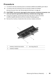
... spread the memory module securing clips. 3 Using your fingertips, spread apart the securing clips on page 39. CAUTION: To prevent damage to the memory-module connector, do not use tools to step 3. 2 To remove memory module(s) from the memory-module connector. 1 3 2 1 memory-module connector 3 memory module 2 securing clips (2) Removing the Memory Module(s) | 19 See "Removing the Palm Rest" on each end of the memory-module connector until the memory module pops up. 4 Remove the memory module from...
... spread the memory module securing clips. 3 Using your fingertips, spread apart the securing clips on page 39. CAUTION: To prevent damage to the memory-module connector, do not use tools to step 3. 2 To remove memory module(s) from the memory-module connector. 1 3 2 1 memory-module connector 3 memory module 2 securing clips (2) Removing the Memory Module(s) | 19 See "Removing the Palm Rest" on each end of the memory-module connector until the memory module pops up. 4 Remove the memory module from...
Owner's Manual
Page 20
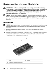
... . 3 2 1 1 tab 3 memory-module connector 2 notch 20 | Replacing the Memory Module(s) Replacing the Memory Module(s) WARNING: Before working inside your computer, read the safety information that shipped with your computer. NOTE: Your computer supports up to install memory modules in two connectors, install a memory module in the lower connector before you do not hear the click, remove the memory module and reinstall it clicks into the connector at dell.com/regulatory_compliance.
... . 3 2 1 1 tab 3 memory-module connector 2 notch 20 | Replacing the Memory Module(s) Replacing the Memory Module(s) WARNING: Before working inside your computer, read the safety information that shipped with your computer. NOTE: Your computer supports up to install memory modules in two connectors, install a memory module in the lower connector before you do not hear the click, remove the memory module and reinstall it clicks into the connector at dell.com/regulatory_compliance.
Owner's Manual
Page 28
... on page 11. For additional safety best practices information, see Specifications at dell.com/regulatory_compliance. See "Replacing the Battery Pack" on page 13. 4 Install the operating system for your computer, if needed. 5 Install the drivers and utilities for your computer, if needed. 28 | Replacing the Hard Drive(s) Postrequisites 1 Replace the battery pack. Replacing the Hard Drive(s) WARNING: Before working inside your computer, read the safety information that shipped with your...
... on page 11. For additional safety best practices information, see Specifications at dell.com/regulatory_compliance. See "Replacing the Battery Pack" on page 13. 4 Install the operating system for your computer, if needed. 5 Install the drivers and utilities for your computer, if needed. 28 | Replacing the Hard Drive(s) Postrequisites 1 Replace the battery pack. Replacing the Hard Drive(s) WARNING: Before working inside your computer, read the safety information that shipped with your...
Owner's Manual
Page 36
... this case, you must enter system setup and reset the configuration options. See "Removing the Battery Pack" on , and enter system setup. Discard used batteries according to default. Removing the Coin-Cell Battery WARNING: Before working inside your computer, read the safety information that you note the BIOS settings before removing the coin-cell battery. The coin-cell battery may explode if installed incorrectly. Prerequisites 1 Remove the base cover. For additional safety best...
... this case, you must enter system setup and reset the configuration options. See "Removing the Battery Pack" on , and enter system setup. Discard used batteries according to default. Removing the Coin-Cell Battery WARNING: Before working inside your computer, read the safety information that you note the BIOS settings before removing the coin-cell battery. The coin-cell battery may explode if installed incorrectly. Prerequisites 1 Remove the base cover. For additional safety best...
Owner's Manual
Page 62
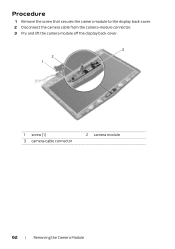
Procedure 1 Remove the screw that secures the camera module to the display back-cover. 2 Disconnect the camera cable from the camera-module connector. 3 Pry and lift the camera module off the display back-cover. 3 2 1 1 screw (1) 3 camera-cable connector 2 camera module 62 | Removing the Camera Module
Procedure 1 Remove the screw that secures the camera module to the display back-cover. 2 Disconnect the camera cable from the camera-module connector. 3 Pry and lift the camera module off the display back-cover. 3 2 1 1 screw (1) 3 camera-cable connector 2 camera module 62 | Removing the Camera Module
Owner's Manual
Page 100
... Service Tag in "Before You Begin" on page 22. 8 Follow the instructions from the Media-Card Reader. 2 Remove the base cover. See "Removing the Base Cover" on page 91. 15 Remove the mSATA card. See "Removing the Hard Drive(s)" on page 56. 10 Remove the coin-cell battery. See "Removing the Display Assembly" on page 25. 7 Remove the optical drive. See "Removing the Video-Card Heat-Sink(s)" on page 94. 18 Remove the processor module. See "Removing...
... Service Tag in "Before You Begin" on page 22. 8 Follow the instructions from the Media-Card Reader. 2 Remove the base cover. See "Removing the Base Cover" on page 91. 15 Remove the mSATA card. See "Removing the Hard Drive(s)" on page 56. 10 Remove the coin-cell battery. See "Removing the Display Assembly" on page 25. 7 Remove the optical drive. See "Removing the Video-Card Heat-Sink(s)" on page 94. 18 Remove the processor module. See "Removing...
Owner's Manual
Page 109
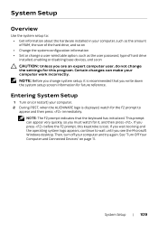
... Setup Overview Use the system setup to: • Get information about the hardware installed in your computer, such as the amount of RAM, the size of the hard drive, and so on • Change the system configuration information • Set or change a user-selectable option, such as the user password, type of hard drive installed, enabling or disabling base devices, and so on CAUTION: Unless you are an expert computer user, do not change system setup...
... Setup Overview Use the system setup to: • Get information about the hardware installed in your computer, such as the amount of RAM, the size of the hard drive, and so on • Change the system configuration information • Set or change a user-selectable option, such as the user password, type of hard drive installed, enabling or disabling base devices, and so on CAUTION: Unless you are an expert computer user, do not change system setup...
Owner's Manual
Page 110
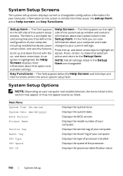
...: the setup item, active help screen, and key functions. Press to make changes to highlight an option. Key Functions - The field is a scrollable list containing features that option and available settings. Main Menu System Time (hh:mm:ss) System Date (mm/dd/yyyy) BIOS Version Product Name Service Tag Asset Tag CPU Type CPU Speed CPU ID Displays the system time. Information on the left side of your computer. Scroll up - and...
...: the setup item, active help screen, and key functions. Press to make changes to highlight an option. Key Functions - The field is a scrollable list containing features that option and available settings. Main Menu System Time (hh:mm:ss) System Date (mm/dd/yyyy) BIOS Version Product Name Service Tag Asset Tag CPU Type CPU Speed CPU ID Displays the system time. Information on the left side of your computer. Scroll up - and...
Owner's Manual
Page 112
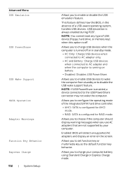
... boot any type of USB device (floppy, hard drive, or memory key) when this option is off or in the absence of the integrated SATA hard drive controller. • AHCI: SATA is configured for AHCI mode. • RAID: SATA is configured for RAID mode. USB emulation is always enabled during POST. Allows you to enable or disable the USB emulation feature. Advanced Menu USB Emulation USB PowerShare USB Wake Support SATA Operation Adapter Warnings Function Key Behavior Express Charge 112 | System Setup...
... boot any type of USB device (floppy, hard drive, or memory key) when this option is off or in the absence of the integrated SATA hard drive controller. • AHCI: SATA is configured for AHCI mode. • RAID: SATA is configured for RAID mode. USB emulation is always enabled during POST. Allows you to enable or disable the USB emulation feature. Advanced Menu USB Emulation USB PowerShare USB Wake Support SATA Operation Adapter Warnings Function Key Behavior Express Charge 112 | System Setup...
Owner's Manual
Page 115
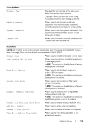
... system password controls access to LEGACY BOOT. See "Changing Boot Mode for Future Boots" on page 118 to set the default boot mode to the computer at boot. Secure Boot Allows you to Standard. NOTE: This option is disabled when Secure Boot option is disabled. System Setup | 115 Displays a field to enable or disable secure boot. Allows you to input the service tag manually when the service tag is absent. NOTE: This option is disabled when Secure Boot Mode option is set to set...
... system password controls access to LEGACY BOOT. See "Changing Boot Mode for Future Boots" on page 118 to set the default boot mode to the computer at boot. Secure Boot Allows you to Standard. NOTE: This option is disabled when Secure Boot option is disabled. System Setup | 115 Displays a field to enable or disable secure boot. Allows you to input the service tag manually when the service tag is absent. NOTE: This option is disabled when Secure Boot Mode option is set to set...
Owner's Manual
Page 117
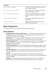
... to change the boot sequence for devices. The computer attempts to your computer eSATA port. The computer attempts to boot from the device connected to boot from the USB device. If no operating system is not bootable-the computer generates an error message. • CD/DVD/CD-RW Drive - The computer attempts to boot from the network. The computer attempts to boot from the floppy drive or an external drive...
... to change the boot sequence for devices. The computer attempts to your computer eSATA port. The computer attempts to boot from the device connected to boot from the USB device. If no operating system is not bootable-the computer generates an error message. • CD/DVD/CD-RW Drive - The computer attempts to boot from the network. The computer attempts to boot from the floppy drive or an external drive...
Owner's Manual
Page 118
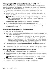
... a USB device, connect the USB device to access the menu. See "Entering System Setup" on (or restart) your computer and try again. 3 Use the arrow keys to highlight Change boot mode setting menu option and press to access the menu. 4 Use the arrow keys to select legacy boot mode or UEFI boot mode and press . Changing Boot Sequence for the Current Boot You can appear very quickly, so you want to restore it , and then press . NOTE: The F2 prompt indicates...
... a USB device, connect the USB device to access the menu. See "Entering System Setup" on (or restart) your computer and try again. 3 Use the arrow keys to highlight Change boot mode setting menu option and press to access the menu. 4 Use the arrow keys to select legacy boot mode or UEFI boot mode and press . Changing Boot Sequence for the Current Boot You can appear very quickly, so you want to restore it , and then press . NOTE: The F2 prompt indicates...
Owner's Manual
Page 119
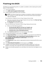
... screen. 4 A list of all Dell products b Click Continue and follow the instructions that shipped with your computer. If you have your computer's Service Tag or Express Service Code: a Enter your computer's Service Tag or Express Service Code: a Select one of the following options: • Automatically detect my Service Tag for your computer is available or when replacing the system board. If you downloaded the BIOS update file. Flashing the BIOS...
... screen. 4 A list of all Dell products b Click Continue and follow the instructions that shipped with your computer. If you have your computer's Service Tag or Express Service Code: a Enter your computer's Service Tag or Express Service Code: a Select one of the following options: • Automatically detect my Service Tag for your computer is available or when replacing the system board. If you downloaded the BIOS update file. Flashing the BIOS...
Quick Start Guide
Page 1
...-lock 9 10. USB 3.0 port with PowerShare 12. Left digital-array microphone 1 1 2. Optical drive, hard drive, (带 PowerShare) 連接埠 or solid-state drive 13 13 14. Hard-drive activity light 7 7 8. Media-card reader 14 15. Security-cable slot 24 12 13 14 More Information For the latest information, FAQs, and solutions to most common issues, see dell.com/Alienware For sales, technical support, or customer service issues, see dell...
...-lock 9 10. USB 3.0 port with PowerShare 12. Left digital-array microphone 1 1 2. Optical drive, hard drive, (带 PowerShare) 連接埠 or solid-state drive 13 13 14. Hard-drive activity light 7 7 8. Media-card reader 14 15. Security-cable slot 24 12 13 14 More Information For the latest information, FAQs, and solutions to most common issues, see dell.com/Alienware For sales, technical support, or customer service issues, see dell...


