Owner's Manual
Page 3
... Safety Instructions 12 2 After Working Inside Your Computer 13 3 Removing the Base Cover 14 Procedure 14 4 Replacing the Base Cover 15 Procedure 15 5 Removing the Battery 16 Prerequisites 16 Procedure 16 6 Replacing the Battery 17 Procedure 17 Postrequisites 17 7 Removing the Memory Module(s) 3 and 4 18 Prerequisites 18 Procedure 19 8 Replacing the Memory Module(s) 3 and 4 20 Procedure 20 Postrequisites 20 9 Removing the Primary Hard Drive 21 Prerequisites 21 Procedure 21 10 Replacing the Primary Hard Drive...
... Safety Instructions 12 2 After Working Inside Your Computer 13 3 Removing the Base Cover 14 Procedure 14 4 Replacing the Base Cover 15 Procedure 15 5 Removing the Battery 16 Prerequisites 16 Procedure 16 6 Replacing the Battery 17 Procedure 17 Postrequisites 17 7 Removing the Memory Module(s) 3 and 4 18 Prerequisites 18 Procedure 19 8 Replacing the Memory Module(s) 3 and 4 20 Procedure 20 Postrequisites 20 9 Removing the Primary Hard Drive 21 Prerequisites 21 Procedure 21 10 Replacing the Primary Hard Drive...
Owner's Manual
Page 5
... 24 Replacing the Video-Card Heat Sink 42 Procedure 42 Postrequisites 42 25 Removing the Video Card 43 Prerequisites 43 Procedure 43 26 Replacing the Video Card 44 Procedure 44 Postrequisites 44 27 Removing the Palm Rest 45 Prerequisites 45 28 Replacing the Palm Rest 49 Procedure 49 Postrequisites 49 29 Removing the Memory Module(s) 1 and 2 50 Prerequisites 50 Procedure 51 30 Replacing the Memory Module(s) 1 and...
... 24 Replacing the Video-Card Heat Sink 42 Procedure 42 Postrequisites 42 25 Removing the Video Card 43 Prerequisites 43 Procedure 43 26 Replacing the Video Card 44 Procedure 44 Postrequisites 44 27 Removing the Palm Rest 45 Prerequisites 45 28 Replacing the Palm Rest 49 Procedure 49 Postrequisites 49 29 Removing the Memory Module(s) 1 and 2 50 Prerequisites 50 Procedure 51 30 Replacing the Memory Module(s) 1 and...

Owner's Manual
Page 12
... that you finish working inside the computer, replace all power sources before opening the computer cover or panels. When connecting cables, ensure that the work , periodically touch an unpainted metal surface to remove the computer cover and access any connector pins. After you must disengage before connecting to avoid bending any of the computer. CAUTION: To avoid damaging the components and cards, handle them evenly...
... that you finish working inside the computer, replace all power sources before opening the computer cover or panels. When connecting cables, ensure that the work , periodically touch an unpainted metal surface to remove the computer cover and access any connector pins. After you must disengage before connecting to avoid bending any of the computer. CAUTION: To avoid damaging the components and cards, handle them evenly...
Owner's Manual
Page 18
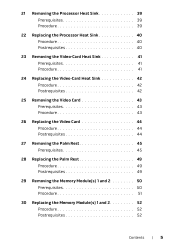
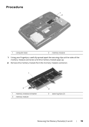
... can access connectors DIMM3 and DIMM4 are located under the base cover. DIMM1 and DIMM2 are located under the keyboard. Your computer supports up to four memory module connectors. Removing the Memory Module(s) 3 and 4 | 18 After working inside your computer and follow the instructions in "Before Working Inside Your Computer" on page 11. See "Removing the Battery" on page 14. 2 Remove the battery. Removing the Memory Module(s) 3 and 4 WARNING: Before working inside...
... can access connectors DIMM3 and DIMM4 are located under the base cover. DIMM1 and DIMM2 are located under the keyboard. Your computer supports up to four memory module connectors. Removing the Memory Module(s) 3 and 4 | 18 After working inside your computer and follow the instructions in "Before Working Inside Your Computer" on page 11. See "Removing the Battery" on page 14. 2 Remove the battery. Removing the Memory Module(s) 3 and 4 WARNING: Before working inside...
Owner's Manual
Page 19
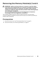
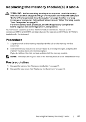
Procedure 1 2 1 computer base 2 memory-module 1 Using your fingertips, carefully spread apart the securing clips at the sides of the memory-module connector until the memory module pops up. 2 Remove the memory module from the memory-module connector. 1 2 1 memory-module connector 3 memory module 3 2 securing clips (2) Removing the Memory Module(s) 3 and 4 | 19
Procedure 1 2 1 computer base 2 memory-module 1 Using your fingertips, carefully spread apart the securing clips at the sides of the memory-module connector until the memory module pops up. 2 Remove the memory module from the memory-module connector. 1 2 1 memory-module connector 3 memory module 3 2 securing clips (2) Removing the Memory Module(s) 3 and 4 | 19
Owner's Manual
Page 20
... memory module. Your computer supports up to four memory module connectors. Procedure 1 Align the notch on the memory module with your computer, follow the steps in "Before Working Inside Your Computer" on page 11. You can access connectors DIMM3 and DIMM4 are located under the base cover. Replacing the Memory Module(s) 3 and 4 | 20 NOTE: The computer may not boot if the memory module is not installed correctly. Replacing the Memory Module...
... memory module. Your computer supports up to four memory module connectors. Procedure 1 Align the notch on the memory module with your computer, follow the steps in "Before Working Inside Your Computer" on page 11. You can access connectors DIMM3 and DIMM4 are located under the base cover. Replacing the Memory Module(s) 3 and 4 | 20 NOTE: The computer may not boot if the memory module is not installed correctly. Replacing the Memory Module...
Owner's Manual
Page 23
.... For more safety best practices, see the Regulatory Compliance home page at dell.com/regulatory_compliance. Postrequisites 1 Replace the battery. Replacing the Primary Hard Drive | 23 Exercise care when handling the hard drive. CAUTION: Hard drives are extremely fragile. After working inside your computer and follow the instructions in "Before Working Inside Your Computer" on page 17. 2 Replace the base cover. See "Replacing the Battery" on page 11.
.... For more safety best practices, see the Regulatory Compliance home page at dell.com/regulatory_compliance. Postrequisites 1 Replace the battery. Replacing the Primary Hard Drive | 23 Exercise care when handling the hard drive. CAUTION: Hard drives are extremely fragile. After working inside your computer and follow the instructions in "Before Working Inside Your Computer" on page 17. 2 Replace the base cover. See "Replacing the Battery" on page 11.

Owner's Manual
Page 26
... home page at dell.com/regulatory_compliance. Replacing the Secondary Hard Drive | 26 Procedure 1 Place the hard drive into the hard-drive bracket. 2 Align the screw holes on the hard-drive bracket with the screw holes on page 11. See "Replacing the Base Cover" on page 17. 2 Replace the base cover. See "Replacing the Battery" on page 15. CAUTION: Hard drives are extremely fragile. Postrequisites 1 Replace the battery. After working inside your computer...
... home page at dell.com/regulatory_compliance. Replacing the Secondary Hard Drive | 26 Procedure 1 Place the hard drive into the hard-drive bracket. 2 Align the screw holes on the hard-drive bracket with the screw holes on page 11. See "Replacing the Base Cover" on page 17. 2 Replace the base cover. See "Replacing the Battery" on page 15. CAUTION: Hard drives are extremely fragile. Postrequisites 1 Replace the battery. After working inside your computer...
Owner's Manual
Page 33
... "Replacing the Battery" on the wireless mini-card Main WLAN + Bluetooth (white triangle) Auxiliary WLAN + Bluetooth (black triangle) Antenna-cable color white black Postrequisites 1 Replace the battery. See "Replacing the Base Cover" on the mini-card connector. 2 Slide the wireless mini-card, at dell.com/regulatory_compliance. Replacing the Wireless Mini-Card WARNING: Before working inside your computer, read the safety information that secures the wireless mini-card to the system board. 4 Connect the antenna cables to...
... "Replacing the Battery" on the wireless mini-card Main WLAN + Bluetooth (white triangle) Auxiliary WLAN + Bluetooth (black triangle) Antenna-cable color white black Postrequisites 1 Replace the battery. See "Replacing the Base Cover" on the mini-card connector. 2 Slide the wireless mini-card, at dell.com/regulatory_compliance. Replacing the Wireless Mini-Card WARNING: Before working inside your computer, read the safety information that secures the wireless mini-card to the system board. 4 Connect the antenna cables to...
Owner's Manual
Page 49
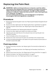
...-Light Board" on page 59. 4 Replace the keyboard. See "Replacing the Power-Button Board" on page 62. 3 Replace the power-button board. See "Replacing the Keyboard" on page 56. 5 Connect the status-light board cable to secure the cable. See "Replacing the Primary Hard Drive" on page 17. 5 Replace the base cover. See "Replacing the Battery" on page 23. 4 Replace the battery. Procedure 1 Replace the keyboard daughter board. Replacing the Palm Rest | 49 See "Replacing the Keyboard Daughter Board" on page 15. Postrequisites 1 Replace the tertiary hard drive. See "Replacing...
...-Light Board" on page 59. 4 Replace the keyboard. See "Replacing the Power-Button Board" on page 62. 3 Replace the power-button board. See "Replacing the Keyboard" on page 56. 5 Connect the status-light board cable to secure the cable. See "Replacing the Primary Hard Drive" on page 17. 5 Replace the base cover. See "Replacing the Battery" on page 23. 4 Replace the battery. Procedure 1 Replace the keyboard daughter board. Replacing the Palm Rest | 49 See "Replacing the Keyboard Daughter Board" on page 15. Postrequisites 1 Replace the tertiary hard drive. See "Replacing...
Owner's Manual
Page 50
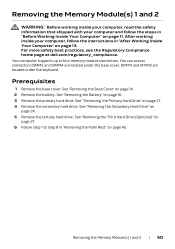
... practices, see the Regulatory Compliance home page at dell.com/regulatory_compliance. DIMM1 and DIMM2 are located under the keyboard. Removing the Memory Module(s) 1 and 2 | 50 You can access connectors DIMM3 and DIMM4 are located under the base cover. Prerequisites 1 Remove the base cover. See "Removing the Battery" on page 16. 3 Remove the primary hard drive. Removing the Memory Module(s) 1 and 2 WARNING: Before working inside your computer, read the safety information...
... practices, see the Regulatory Compliance home page at dell.com/regulatory_compliance. DIMM1 and DIMM2 are located under the keyboard. Removing the Memory Module(s) 1 and 2 | 50 You can access connectors DIMM3 and DIMM4 are located under the base cover. Prerequisites 1 Remove the base cover. See "Removing the Battery" on page 16. 3 Remove the primary hard drive. Removing the Memory Module(s) 1 and 2 WARNING: Before working inside your computer, read the safety information...
Owner's Manual
Page 51
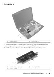
Procedure 1 2 1 memory-module 2 computer base 1 Using your fingertips, carefully spread apart the securing clips at the sides of the memory-module connector until the memory module pops up. 2 Slide and remove the memory module from the memory-module connector. 1 2 1 memory-module connector 3 memory module 3 2 securing clips (2) Removing the Memory Module(s) 1 and 2 | 51
Procedure 1 2 1 memory-module 2 computer base 1 Using your fingertips, carefully spread apart the securing clips at the sides of the memory-module connector until the memory module pops up. 2 Slide and remove the memory module from the memory-module connector. 1 2 1 memory-module connector 3 memory module 3 2 securing clips (2) Removing the Memory Module(s) 1 and 2 | 51
Owner's Manual
Page 52
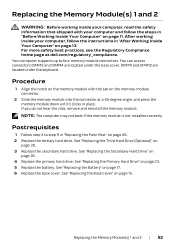
... located under the keyboard. Postrequisites 1 Follow step 5 to four memory module connectors. See "Replacing the Battery" on page 26. 4 Replace the primary hard drive. See "Replacing the Secondary Hard Drive" on page 17. 6 Replace the base cover. Replacing the Memory Module(s) 1 and 2 | 52 See "Replacing the Third Hard Drive (Optional)" on the memory-module connector. 2 Slide the memory module into the connector at dell.com/regulatory_compliance. NOTE: The computer may not boot if the memory module is not installed correctly. After working...
... located under the keyboard. Postrequisites 1 Follow step 5 to four memory module connectors. See "Replacing the Battery" on page 26. 4 Replace the primary hard drive. See "Replacing the Secondary Hard Drive" on page 17. 6 Replace the base cover. Replacing the Memory Module(s) 1 and 2 | 52 See "Replacing the Third Hard Drive (Optional)" on the memory-module connector. 2 Slide the memory module into the connector at dell.com/regulatory_compliance. NOTE: The computer may not boot if the memory module is not installed correctly. After working...
Owner's Manual
Page 71
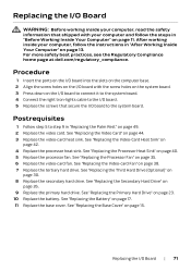
.... See "Replacing the Video Card" on page 15. See "Replacing the Third Hard Drive (Optional)" on page 26. 9 Replace the primary hard drive. See "Replacing the Secondary Hard Drive" on page 30. 8 Replace the secondary hard drive. See "Replacing the Primary Hard Drive" on page 38. 7 Replace the tertiary hard drive. Postrequisites 1 Follow step 5 to the system board. See "Replacing the Video-card Fan" on page 23. 10 Replace the battery. Procedure 1 Insert the ports on the I/O board into the slots on...
.... See "Replacing the Video Card" on page 15. See "Replacing the Third Hard Drive (Optional)" on page 26. 9 Replace the primary hard drive. See "Replacing the Secondary Hard Drive" on page 30. 8 Replace the secondary hard drive. See "Replacing the Primary Hard Drive" on page 38. 7 Replace the tertiary hard drive. Postrequisites 1 Follow step 5 to the system board. See "Replacing the Video-card Fan" on page 23. 10 Replace the battery. Procedure 1 Insert the ports on the I/O board into the slots on...
Owner's Manual
Page 81
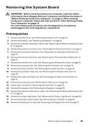
... Remove the memory modules(s) 1 and 2. See "Removing the Speakers" on page 24. 6 Remove the tertiary hard drive. Prerequisites 1 Remove the base cover. See "Removing the Wireless Mini-Card" on page 36. 10 Remove the processor heat sink. See "Removing the Video-card Fan" on page 31. 8 Remove the processor fan. See "Removing the Video Card" on page 43. 13 Follow step 1 to step 8 in "Removing the Palm Rest" on page 60. 17 Remove the power-button board. See "Removing...
... Remove the memory modules(s) 1 and 2. See "Removing the Speakers" on page 24. 6 Remove the tertiary hard drive. Prerequisites 1 Remove the base cover. See "Removing the Wireless Mini-Card" on page 36. 10 Remove the processor heat sink. See "Removing the Video-card Fan" on page 31. 8 Remove the processor fan. See "Removing the Video Card" on page 43. 13 Follow step 1 to step 8 in "Removing the Palm Rest" on page 60. 17 Remove the power-button board. See "Removing...
Owner's Manual
Page 87
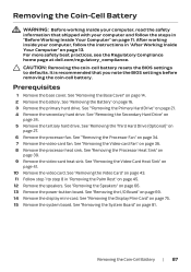
Prerequisites 1 Remove the base cover. See ""Removing the Primary Hard Drive" on page 66. 13 Remove the power-button board. See "Removing the Speakers" on page 21. 4 Remove the secondary hard drive. Removing the Coin-Cell Battery WARNING: Before working inside your computer, read the safety information that you note the BIOS settings before removing the coin-cell battery. See "Removing the Base Cover" on page 39. 9 Remove the video-card heat sink. See "Removing the Processor...
Prerequisites 1 Remove the base cover. See ""Removing the Primary Hard Drive" on page 66. 13 Remove the power-button board. See "Removing the Speakers" on page 21. 4 Remove the secondary hard drive. Removing the Coin-Cell Battery WARNING: Before working inside your computer, read the safety information that you note the BIOS settings before removing the coin-cell battery. See "Removing the Base Cover" on page 39. 9 Remove the video-card heat sink. See "Removing the Processor...
Owner's Manual
Page 120
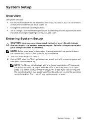
..., such as the user password, type of the hard drive, and so on. • Change the system setup configurations. • Set or change system setup, it , and then press . Certain changes can appear very quickly, so you change a user-selectable option, such as the amount of RAM, the size of hard drive installed, enabling or disabling base devices, and so on (or restart) your computer. 2 During POST, when the DELL logo is displayed, watch for...
..., such as the user password, type of the hard drive, and so on. • Change the system setup configurations. • Set or change system setup, it , and then press . Certain changes can appear very quickly, so you change a user-selectable option, such as the amount of RAM, the size of hard drive installed, enabling or disabling base devices, and so on (or restart) your computer. 2 During POST, when the DELL logo is displayed, watch for...

Owner's Manual
Page 121
... configuration of your current settings. Scroll up and down the list with the up - Press to make changes to your computer. Displays the type of the system setup window. System Setup | 121 Setup Item - Press the up - Key Functions - Main Menu System Time (hh:mm:ss) System Date (mm/dd/yyyy) BIOS Version Product Name Service Tag Asset Tag CPU Type CPU Speed CPU ID CPU Cache L1 Cache Displays the system time. Displays...
... configuration of your current settings. Scroll up and down the list with the up - Press to make changes to your computer. Displays the type of the system setup window. System Setup | 121 Setup Item - Press the up - Key Functions - Main Menu System Time (hh:mm:ss) System Date (mm/dd/yyyy) BIOS Version Product Name Service Tag Asset Tag CPU Type CPU Speed CPU ID CPU Cache L1 Cache Displays the system time. Displays...

Owner's Manual
Page 123
... cannot boot any type of USB device (floppy, hard drive, or memory key) when this option is off or in standby mode. • AC Only: Charge USB devices when connected to AC adapter only. • AC and Battery: Charge USB devices when connected to configure the operating mode of a USB-aware operating system, handles USB devices. Allows you to disable the USB wake support feature. Enabled: BIOS will detect unsupported AC adapters and display an error on or in the absence of the integrated SATA hard drive controller...
... cannot boot any type of USB device (floppy, hard drive, or memory key) when this option is off or in standby mode. • AC Only: Charge USB devices when connected to AC adapter only. • AC and Battery: Charge USB devices when connected to configure the operating mode of a USB-aware operating system, handles USB devices. Allows you to disable the USB wake support feature. Enabled: BIOS will detect unsupported AC adapters and display an error on or in the absence of the integrated SATA hard drive controller...
Owner's Manual
Page 126
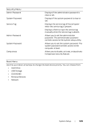
... manually when the service tag is present. Boot Menu Use the up or down arrow keys to the computer at boot. Allows you to set the administrator password. You can choose from: • Hard Drive • USB Storage • CD/DVD/BD • Removal Devices • Network System Setup | 126 Allows you to the system setup utility. The system password controls access to change the boot device priority. Displays if the system password is clear or set . Security Menu Admin Password...
... manually when the service tag is present. Boot Menu Use the up or down arrow keys to the computer at boot. Allows you to set the administrator password. You can choose from: • Hard Drive • USB Storage • CD/DVD/BD • Removal Devices • Network System Setup | 126 Allows you to the system setup utility. The system password controls access to change the boot device priority. Displays if the system password is clear or set . Security Menu Admin Password...


