Handling swollen Lithium-ion batteries
Page 1
... electronics industry due to customer preferences for handling and replacing Lithium-ion batteries ● Exercise caution when handling Lithium-ion batteries. ● Discharge the battery before removing it from Dell that is designed to replace a swollen battery under the terms of lithium-ion battery is fully discharged. ● Do not crush, drop, mutilate, or penetrate the...
... electronics industry due to customer preferences for handling and replacing Lithium-ion batteries ● Exercise caution when handling Lithium-ion batteries. ● Discharge the battery before removing it from Dell that is designed to replace a swollen battery under the terms of lithium-ion battery is fully discharged. ● Do not crush, drop, mutilate, or penetrate the...

Handling swollen Lithium-ion batteries
Page 2
Frequently Asked Questions. 2 For more information on how to improve the performance and lifespan of the issue, see Dell Laptop Battery - Lithium-ion batteries can swell for various reasons such as age, number of charge cycles, or exposure to minimize the possibility of occurrence of the laptop battery and to high heat.
Frequently Asked Questions. 2 For more information on how to improve the performance and lifespan of the issue, see Dell Laptop Battery - Lithium-ion batteries can swell for various reasons such as age, number of charge cycles, or exposure to minimize the possibility of occurrence of the laptop battery and to high heat.
Service Manual
Page 5
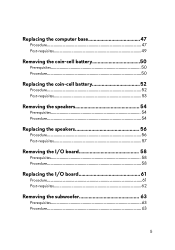
Replacing the computer base 47 Procedure 47 Post-requisites 49 Removing the coin-cell battery 50 Prerequisites 50 Procedure 50 Replacing the coin-cell battery 52 Procedure 52 Post-requisites 53 Removing the speakers 54 Prerequisites 54 Procedure 54 Replacing the speakers 56 Procedure 56 Post-requisites 57 Removing the I/O board 58 Prerequisites 58 Procedure 58 Replacing the I/O board 61 Procedure 61 Post-requisites 62 Removing the subwoofer 63 Prerequisites 63 Procedure 63 5
Replacing the computer base 47 Procedure 47 Post-requisites 49 Removing the coin-cell battery 50 Prerequisites 50 Procedure 50 Replacing the coin-cell battery 52 Procedure 52 Post-requisites 53 Removing the speakers 54 Prerequisites 54 Procedure 54 Replacing the speakers 56 Procedure 56 Post-requisites 57 Removing the I/O board 58 Prerequisites 58 Procedure 58 Replacing the I/O board 61 Procedure 61 Post-requisites 62 Removing the subwoofer 63 Prerequisites 63 Procedure 63 5
Service Manual
Page 7
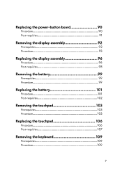
Replacing the power-button board 90 Procedure 90 Post-requisites 91 Removing the display assembly 92 Prerequisites 92 Procedure 93 Replacing the display assembly 96 Procedure 96 Post-requisites 98 Removing the battery 99 Prerequisites 99 Procedure 99 Replacing the battery 101 Procedure 101 Post-requisites 102 Removing the touchpad 103 Prerequisites 103 Procedure 103 Replacing the touchpad 106 Procedure 106 Post-requisites 107 Removing the keyboard 109 Prerequisites 109 Procedure 109 7
Replacing the power-button board 90 Procedure 90 Post-requisites 91 Removing the display assembly 92 Prerequisites 92 Procedure 93 Replacing the display assembly 96 Procedure 96 Post-requisites 98 Removing the battery 99 Prerequisites 99 Procedure 99 Replacing the battery 101 Procedure 101 Post-requisites 102 Removing the touchpad 103 Prerequisites 103 Procedure 103 Replacing the touchpad 106 Procedure 106 Post-requisites 107 Removing the keyboard 109 Prerequisites 109 Procedure 109 7
Service Manual
Page 12
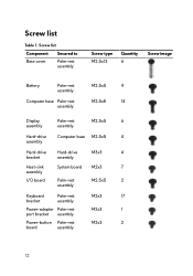
Screw list Table 1. Screw list Component Secured to Base cover Palm-rest assembly Screw type M2.5x13 Quantity 6 Screw image Battery Palm-rest assembly Computer base Palm-rest assembly M2.5x5 4 M2.5x8 14 Display assembly Palm-rest assembly M2.5x5 6 Hard-drive Computer ... assembly Hard-drive Hard-drive M3x3 4 bracket assembly Heat-sink System board M2x3 7 assembly I/O board Palm-rest assembly M2.5x5 2 Keyboard Palm-rest M2x3 17 bracket assembly Power-adapter Palm-rest M2x3 1 port bracket assembly Power-button Palm-rest M2x3 2 board assembly 12
Screw list Table 1. Screw list Component Secured to Base cover Palm-rest assembly Screw type M2.5x13 Quantity 6 Screw image Battery Palm-rest assembly Computer base Palm-rest assembly M2.5x5 4 M2.5x8 14 Display assembly Palm-rest assembly M2.5x5 6 Hard-drive Computer ... assembly Hard-drive Hard-drive M3x3 4 bracket assembly Heat-sink System board M2x3 7 assembly I/O board Palm-rest assembly M2.5x5 2 Keyboard Palm-rest M2x3 17 bracket assembly Power-adapter Palm-rest M2x3 1 port bracket assembly Power-button Palm-rest M2x3 2 board assembly 12
Service Manual
Page 17
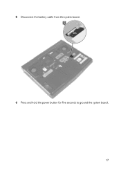
5 Disconnect the battery cable from the system board. 6 Press and hold the power button for five seconds to ground the system board. 17
5 Disconnect the battery cable from the system board. 6 Press and hold the power button for five seconds to ground the system board. 17
Service Manual
Page 18
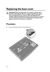
For more safety best practices, see the Regulatory Compliance home page at www.dell.com/regulatory_compliance. Procedure 1 Connect the battery cable to the system board. 18 After working inside your computer, follow the steps in After working inside your computer. Replacing the base cover WARNING: Before working inside your computer, read the safety information that shipped with your computer and follow the instructions in Before working inside your computer.
For more safety best practices, see the Regulatory Compliance home page at www.dell.com/regulatory_compliance. Procedure 1 Connect the battery cable to the system board. 18 After working inside your computer, follow the steps in After working inside your computer. Replacing the base cover WARNING: Before working inside your computer, read the safety information that shipped with your computer and follow the instructions in Before working inside your computer.
Service Manual
Page 50
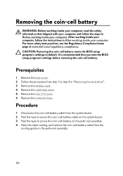
...: Before working inside your computer, read the safety information that you note the BIOS setup program's settings before removing the coin-cell battery. It is recommended that shipped with your computer and follow the instructions in "Removing the hard drive". 3 Remove the wireless card...board. 2 Peel the tape to access the coin-cell battery cable on the palm-rest assembly. 50 For more safety best practices, see the Regulatory Compliance home page at www.dell.com/regulatory_compliance. Procedure 1 Disconnect the coin-cell battery cable from the routing guide on the system board. ...
...: Before working inside your computer, read the safety information that you note the BIOS setup program's settings before removing the coin-cell battery. It is recommended that shipped with your computer and follow the instructions in "Removing the hard drive". 3 Remove the wireless card...board. 2 Peel the tape to access the coin-cell battery cable on the palm-rest assembly. 50 For more safety best practices, see the Regulatory Compliance home page at www.dell.com/regulatory_compliance. Procedure 1 Disconnect the coin-cell battery cable from the routing guide on the system board. ...
Service Manual
Page 51
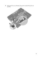
5 Gently peel the coin-cell battery along with its cable off the palm-rest assembly. 51
5 Gently peel the coin-cell battery along with its cable off the palm-rest assembly. 51
Service Manual
Page 52
... the Regulatory Compliance home page at www.dell.com/regulatory_compliance. Procedure 1 Adhere the coin-cell battery to the palm-rest assembly. 2 Adhere the tape that secures the coin-cell battery to the palm-rest assembly. 3 Route the coin-cell battery cable through the routing guide and adhere the... computer, follow the steps in After working inside your computer. Replacing the coin-cell battery WARNING: Before working inside your computer, read the safety information that secures the coin-cell battery cable to the system board. 4 Adhere the tape that shipped with your computer and...
... the Regulatory Compliance home page at www.dell.com/regulatory_compliance. Procedure 1 Adhere the coin-cell battery to the palm-rest assembly. 2 Adhere the tape that secures the coin-cell battery to the palm-rest assembly. 3 Route the coin-cell battery cable through the routing guide and adhere the... computer, follow the steps in After working inside your computer. Replacing the coin-cell battery WARNING: Before working inside your computer, read the safety information that secures the coin-cell battery cable to the system board. 4 Adhere the tape that shipped with your computer and...
Service Manual
Page 53
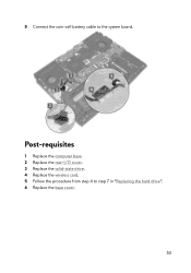
Post-requisites 1 Replace the computer base. 2 Replace the rear-I/O cover. 3 Replace the solid-state drive. 4 Replace the wireless card. 5 Follow the procedure from step 4 to the system board. 5 Connect the coin-cell battery cable to step 7 in "Replacing the hard drive". 6 Replace the base cover. 53
Post-requisites 1 Replace the computer base. 2 Replace the rear-I/O cover. 3 Replace the solid-state drive. 4 Replace the wireless card. 5 Follow the procedure from step 4 to the system board. 5 Connect the coin-cell battery cable to step 7 in "Replacing the hard drive". 6 Replace the base cover. 53
Service Manual
Page 69
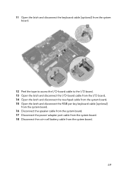
11 Open the latch and disconnect the keyboard cable (optional) from the system board. 12 Peel the tape to access the I/O-board cable to the I/O board. 13 Open the latch and disconnect the I/O-board cable from the I/O board. 14 Open the latch and disconnect the touchpad cable from the system board. 15 Open the latch and disconnect the RGB per key keyboard cable (optional) from the system board. 16 Disconnect the speaker cable from the system board. 17 Disconnect the power-adapter port cable from the system board. 18 Disconnect the coin-cell battery cable from the system board. 69
11 Open the latch and disconnect the keyboard cable (optional) from the system board. 12 Peel the tape to access the I/O-board cable to the I/O board. 13 Open the latch and disconnect the I/O-board cable from the I/O board. 14 Open the latch and disconnect the touchpad cable from the system board. 15 Open the latch and disconnect the RGB per key keyboard cable (optional) from the system board. 16 Disconnect the speaker cable from the system board. 17 Disconnect the power-adapter port cable from the system board. 18 Disconnect the coin-cell battery cable from the system board. 69

Service Manual
Page 70
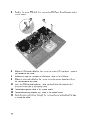
19 Peel the tape that secures the coin-cell battery cable to the system board. 20 Remove the screw (M2.5x5) that secures the USB Type-C port bracket to the system board and lift the USB Type-C port bracket off the system board. 21 Remove the seven screws (M2.5x5) that secure the system-board assembly to the palm-rest assembly. 70
19 Peel the tape that secures the coin-cell battery cable to the system board. 20 Remove the screw (M2.5x5) that secures the USB Type-C port bracket to the system board and lift the USB Type-C port bracket off the system board. 21 Remove the seven screws (M2.5x5) that secure the system-board assembly to the palm-rest assembly. 70
Service Manual
Page 74
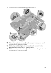
.... 11 Connect the speaker cable to the system board. 12 Connect the power-adapter port cable to the system board. 13 Route the coin-cell battery through the routing channel and adhere the tape to secure the cable. 74
.... 11 Connect the speaker cable to the system board. 12 Connect the power-adapter port cable to the system board. 13 Route the coin-cell battery through the routing channel and adhere the tape to secure the cable. 74
Service Manual
Page 75
14 Connect the coin-cell battery cable to the system board. 15 Slide the keyboard cable (optional) into the connector on the system board and close the latch to secure the cable. 16 Slide the keyboard-backlight cable (optional) into the connector on the system board and close the latch to secure the cable. 17 Slide the macro-keys cable (optional) into the connector on the system board and close the latch to secure the cable. 75
14 Connect the coin-cell battery cable to the system board. 15 Slide the keyboard cable (optional) into the connector on the system board and close the latch to secure the cable. 16 Slide the keyboard-backlight cable (optional) into the connector on the system board and close the latch to secure the cable. 17 Slide the macro-keys cable (optional) into the connector on the system board and close the latch to secure the cable. 75
Service Manual
Page 99
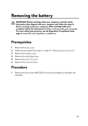
...: Before working inside your computer, read the safety information that secure the battery to step 4 in "Removing the hard drive". 3 Remove the wireless card. 4 Remove the solid-state drive. 5 Remove the rear-I/O cover. 6 Remove the computer base. After ... cover. 2 Follow the procedure from step 1 to the palm-rest assembly. 99 For more safety best practices, see the Regulatory Compliance home page at www.dell.com/regulatory_compliance.
...: Before working inside your computer, read the safety information that secure the battery to step 4 in "Removing the hard drive". 3 Remove the wireless card. 4 Remove the solid-state drive. 5 Remove the rear-I/O cover. 6 Remove the computer base. After ... cover. 2 Follow the procedure from step 1 to the palm-rest assembly. 99 For more safety best practices, see the Regulatory Compliance home page at www.dell.com/regulatory_compliance.
Service Manual
Page 100
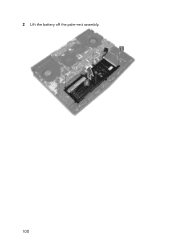
2 Lift the battery off the palm-rest assembly. 100
2 Lift the battery off the palm-rest assembly. 100
Service Manual
Page 101
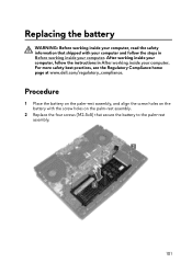
For more safety best practices, see the Regulatory Compliance home page at www.dell.com/regulatory_compliance. After working inside your computer, follow the steps in After working inside your computer. Procedure 1 Place the battery on the palm-rest assembly, and align the screw holes on the palm... the four screws (M2.5x5) that secure the battery to the palm-rest assembly. 101 Replacing the battery WARNING: Before working inside your computer, read the safety information that shipped with the screw holes on the battery with your computer and follow the instructions in Before ...
For more safety best practices, see the Regulatory Compliance home page at www.dell.com/regulatory_compliance. After working inside your computer, follow the steps in After working inside your computer. Procedure 1 Place the battery on the palm-rest assembly, and align the screw holes on the palm... the four screws (M2.5x5) that secure the battery to the palm-rest assembly. 101 Replacing the battery WARNING: Before working inside your computer, read the safety information that shipped with the screw holes on the battery with your computer and follow the instructions in Before ...
Service Manual
Page 103
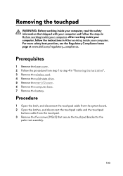
...in "Removing the hard drive". 3 Remove the wireless card. 4 Remove the solid-state drive. 5 Remove the rear-I/O cover. 6 Remove the computer base. 7 Remove the battery. Procedure 1 Open the latch, and disconnect the touchpad cable from the system board. 2 Open the latches, and disconnect the touchpad cable and the touchpad buttons... cable from step 1 to the palm-rest assembly. 103 For more safety best practices, see the Regulatory Compliance home page at www.dell.com/regulatory_compliance. After working inside your computer, follow the steps in Before working inside your computer.
...in "Removing the hard drive". 3 Remove the wireless card. 4 Remove the solid-state drive. 5 Remove the rear-I/O cover. 6 Remove the computer base. 7 Remove the battery. Procedure 1 Open the latch, and disconnect the touchpad cable from the system board. 2 Open the latches, and disconnect the touchpad cable and the touchpad buttons... cable from step 1 to the palm-rest assembly. 103 For more safety best practices, see the Regulatory Compliance home page at www.dell.com/regulatory_compliance. After working inside your computer, follow the steps in Before working inside your computer.
Service Manual
Page 107
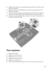
Post-requisites 1 Replace the battery. 2 Replace the computer base. 3 Replace the rear-I/O cover. 4 Replace the solid-state drive. 5 Replace the wireless card. 6 Follow the procedure from step 4 to secure the ...
Post-requisites 1 Replace the battery. 2 Replace the computer base. 3 Replace the rear-I/O cover. 4 Replace the solid-state drive. 5 Replace the wireless card. 6 Follow the procedure from step 4 to secure the ...

