Specifications
Page 1
... the configuration you ordered. Copyright © 2015 Dell Inc. and international copyright and intellectual property laws. in this document may be trademarks of Dell Inc. Dell™ and the Dell logo are trademarks of their respective companies. 2015-08 Rev. All rights reserved. This product is protected by U.S. All other jurisdictions. A00 Regulatory model: P43F | Type: P43F002 Computer model: Alienware 17 R3 Views Specifications
... the configuration you ordered. Copyright © 2015 Dell Inc. and international copyright and intellectual property laws. in this document may be trademarks of Dell Inc. Dell™ and the Dell logo are trademarks of their respective companies. 2015-08 Rev. All rights reserved. This product is protected by U.S. All other jurisdictions. A00 Regulatory model: P43F | Type: P43F002 Computer model: Alienware 17 R3 Views Specifications
Specifications
Page 3
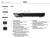
... provide sound output. 6 Headset port Connect a headphone, a microphone, or a headset (headphone and microphone combo). Specifications Left Back Left Views 12 3 4 56 Right Base Display 1 Power-adapter port Connect a power adapter to provide power to your computer and charge the battery. 2 Security-cable slot Connect a security cable to prevent unauthorized movement of your computer is turned off or in Hibernate state, you must disconnect and connect it again to enable charging. 4 USB 3.0 port Connect peripherals such as storage devices...
... provide sound output. 6 Headset port Connect a headphone, a microphone, or a headset (headphone and microphone combo). Specifications Left Back Left Views 12 3 4 56 Right Base Display 1 Power-adapter port Connect a power adapter to provide power to your computer and charge the battery. 2 Security-cable slot Connect a security cable to prevent unauthorized movement of your computer is turned off or in Hibernate state, you must disconnect and connect it again to enable charging. 4 USB 3.0 port Connect peripherals such as storage devices...
Specifications
Page 17
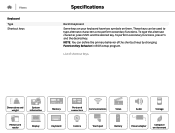
... used to type alternate characters or to perform secondary functions. Dimensions and weight System information Memory Ports and connectors Communications Video Audio Storage Media-card reader Display Keyboard Camera Touch pad Battery Power adapter Computer environment These keys can define the primary behavior of shortcut keys. List of the shortcut keys by changing Function Key Behavior in BIOS setup program. To type the alternate character, press Shift and the desired key. To perform secondary functions, press Fn and the desired key...
... used to type alternate characters or to perform secondary functions. Dimensions and weight System information Memory Ports and connectors Communications Video Audio Storage Media-card reader Display Keyboard Camera Touch pad Battery Power adapter Computer environment These keys can define the primary behavior of shortcut keys. List of the shortcut keys by changing Function Key Behavior in BIOS setup program. To type the alternate character, press Shift and the desired key. To perform secondary functions, press Fn and the desired key...
Specifications
Page 18
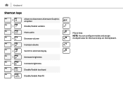
Keyboard Shortcut keys Allows to disconnect Alienware Graphics Amplifier Disable/Enable wireless Mute audio Decrease volume Increase volume Switch to external display Decrease brightness Increase brightness Disable/Enable touchpad Disable/Enable AlienFX Macro keys NOTE: You can configure modes and assign multiple tasks for the macro keys on the keyboard.
Keyboard Shortcut keys Allows to disconnect Alienware Graphics Amplifier Disable/Enable wireless Mute audio Decrease volume Increase volume Switch to external display Decrease brightness Increase brightness Disable/Enable touchpad Disable/Enable AlienFX Macro keys NOTE: You can configure modes and assign multiple tasks for the macro keys on the keyboard.
Service Manual
Page 3
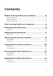
Contents Before working inside your computer 12 Before you begin 12 Safety instructions 12 Recommended tools 13 After working inside your computer 14 Removing the base panel 15 Procedure...15 Replacing the base panel 17 Procedure...17 Removing the memory modules 18 Prerequisites...18 Procedure...18 Replacing the memory modules 20 Procedure...20 Post-requisites 21 Removing the solid-state drives 22 Prerequisites...22 Procedure...22 Replacing the solid-state drives 24 Procedure...24 Post-requisites 24 3
Contents Before working inside your computer 12 Before you begin 12 Safety instructions 12 Recommended tools 13 After working inside your computer 14 Removing the base panel 15 Procedure...15 Replacing the base panel 17 Procedure...17 Removing the memory modules 18 Prerequisites...18 Procedure...18 Replacing the memory modules 20 Procedure...20 Post-requisites 21 Removing the solid-state drives 22 Prerequisites...22 Procedure...22 Replacing the solid-state drives 24 Procedure...24 Post-requisites 24 3
Service Manual
Page 10
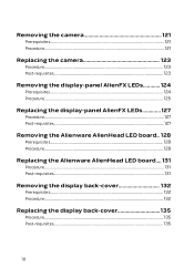
... Procedure...121 Replacing the camera 123 Procedure...123 Post-requisites 123 Removing the display-panel AlienFX LEDs 124 Prerequisites 124 Procedure...125 Replacing the display-panel AlienFX LEDs 127 Procedure...127 Post-requisites 127 Removing the Alienware AlienHead LED board.. 128 Prerequisites 128 Procedure...128 Replacing the Alienware AlienHead LED board.... 131 Procedure...131 Post-requisites 131 Removing the display back-cover 132 Prerequisites 132 Procedure...132 Replacing the display back-cover 135 Procedure...
... Procedure...121 Replacing the camera 123 Procedure...123 Post-requisites 123 Removing the display-panel AlienFX LEDs 124 Prerequisites 124 Procedure...125 Replacing the display-panel AlienFX LEDs 127 Procedure...127 Post-requisites 127 Removing the Alienware AlienHead LED board.. 128 Prerequisites 128 Procedure...128 Replacing the Alienware AlienHead LED board.... 131 Procedure...131 Post-requisites 131 Removing the display back-cover 132 Prerequisites 132 Procedure...132 Replacing the display back-cover 135 Procedure...
Service Manual
Page 12
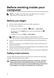
Before you begin 1 Save and close all open files and exit all attached devices and peripherals, such as keyboard, mouse, monitor, and so on the configuration you are using a different operating system, see the Regulatory Compliance home page at www.dell.com/regulatory_compliance. 12 Windows 7: Click or tap Start → Shut down . - NOTE: If you ordered. Safety instructions Use the following safety guidelines to protect...
Before you begin 1 Save and close all open files and exit all attached devices and peripherals, such as keyboard, mouse, monitor, and so on the configuration you are using a different operating system, see the Regulatory Compliance home page at www.dell.com/regulatory_compliance. 12 Windows 7: Click or tap Start → Shut down . - NOTE: If you ordered. Safety instructions Use the following safety guidelines to protect...
Service Manual
Page 13
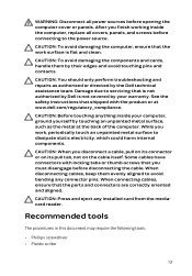
... them evenly aligned to avoid bending any installed card from the mediacard reader. Damage due to servicing that the work , periodically touch an unpainted metal surface to dissipate static electricity, which could harm internal components. CAUTION: Before touching anything inside the computer, replace all power sources before opening the computer cover or panels. After you disconnect a cable, pull on its connector or on its...
... them evenly aligned to avoid bending any installed card from the mediacard reader. Damage due to servicing that the work , periodically touch an unpainted metal surface to dissipate static electricity, which could harm internal components. CAUTION: Before touching anything inside the computer, replace all power sources before opening the computer cover or panels. After you disconnect a cable, pull on its connector or on its...
Service Manual
Page 14
After working inside your computer CAUTION: Leaving stray or loose screws inside your computer may severely damage your computer. 1 Replace all screws and ensure that no stray screws remain inside your computer. 2 Connect any external devices, peripherals, and cables you removed before working on your computer. 3 Replace any media cards, discs, and any other parts that you removed before working on your computer. 4 Connect your computer and all attached devices to their electrical outlets. 5 Turn on your computer. 14
After working inside your computer CAUTION: Leaving stray or loose screws inside your computer may severely damage your computer. 1 Replace all screws and ensure that no stray screws remain inside your computer. 2 Connect any external devices, peripherals, and cables you removed before working on your computer. 3 Replace any media cards, discs, and any other parts that you removed before working on your computer. 4 Connect your computer and all attached devices to their electrical outlets. 5 Turn on your computer. 14
Service Manual
Page 18
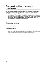
... the Regulatory Compliance home page at www.dell.com/regulatory_compliance. Procedure 1 Using your fingertips, carefully spread apart the securing clips on each end of the memory-module slot until the memory module pops up. 18 Removing the memory modules WARNING: Before working inside your computer, read the safety information that shipped with your computer and follow the instructions in Before working inside your computer.
... the Regulatory Compliance home page at www.dell.com/regulatory_compliance. Procedure 1 Using your fingertips, carefully spread apart the securing clips on each end of the memory-module slot until the memory module pops up. 18 Removing the memory modules WARNING: Before working inside your computer, read the safety information that shipped with your computer and follow the instructions in Before working inside your computer.
Service Manual
Page 21
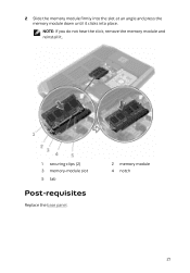
2 Slide the memory module firmly into place. NOTE: If you do not hear the click, remove the memory module and reinstall it clicks into the slot at an angle and press the memory module down until it . 1 securing clips (2) 3 memory-module slot 5 tab Post-requisites Replace the base panel. 2 memory module 4 notch 21
2 Slide the memory module firmly into place. NOTE: If you do not hear the click, remove the memory module and reinstall it clicks into the slot at an angle and press the memory module down until it . 1 securing clips (2) 3 memory-module slot 5 tab Post-requisites Replace the base panel. 2 memory module 4 notch 21
Service Manual
Page 79
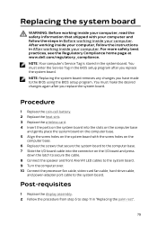
... I/O board and press down the latch to secure the cable. 8 Connect the speaker and front AlienFX LED cables to the system board. 9 Turn the computer over. 10 Connect the processor-fan cable, video-card fan cable, hard-drive cable, and power-adapter port cable to the system board. After working inside your computer, follow the steps in the BIOS setup program after you replace the system board. NOTE: Replacing the system board removes any changes you have made to the BIOS using the BIOS setup...
... I/O board and press down the latch to secure the cable. 8 Connect the speaker and front AlienFX LED cables to the system board. 9 Turn the computer over. 10 Connect the processor-fan cable, video-card fan cable, hard-drive cable, and power-adapter port cable to the system board. After working inside your computer, follow the steps in the BIOS setup program after you replace the system board. NOTE: Replacing the system board removes any changes you have made to the BIOS using the BIOS setup...
Service Manual
Page 88
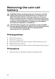
CAUTION: Removing the coin-cell battery resets the BIOS setup program's settings to step 7 in After working inside your computer. Prerequisites 1 Remove the base panel. 2 Remove the wireless card. 3 Follow the procedure from step 1 to step 9 in "Removing the palm rest". 4 Remove the display assembly. 5 Follow the procedure from the system board. 88 After working inside your computer, follow the steps in Before working inside your computer. It is...
CAUTION: Removing the coin-cell battery resets the BIOS setup program's settings to step 7 in After working inside your computer. Prerequisites 1 Remove the base panel. 2 Remove the wireless card. 3 Follow the procedure from step 1 to step 9 in "Removing the palm rest". 4 Remove the display assembly. 5 Follow the procedure from the system board. 88 After working inside your computer, follow the steps in Before working inside your computer. It is...
Service Manual
Page 121
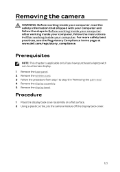
... 1 Place the display back-cover assembly on a flat surface. 2 Using a plastic scribe, pry the camera module off the display back-cover. 121 For more safety best practices, see the Regulatory Compliance home page at www.dell.com/regulatory_compliance. Removing the camera WARNING: Before working inside your computer, read the safety information that shipped with non-touchscreen display. 1 Remove the base panel. 2 Remove the wireless card. 3 Follow the...
... 1 Place the display back-cover assembly on a flat surface. 2 Using a plastic scribe, pry the camera module off the display back-cover. 121 For more safety best practices, see the Regulatory Compliance home page at www.dell.com/regulatory_compliance. Removing the camera WARNING: Before working inside your computer, read the safety information that shipped with non-touchscreen display. 1 Remove the base panel. 2 Remove the wireless card. 3 Follow the...
Service Manual
Page 135
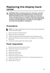
... display-board cable through the routing guides on the display back-cover. 5 Connect the camera cable to step 11 in "Replacing the palm rest". 8 Replace the wireless card. 9 Replace the base panel. 135 For more safety best practices, see the Regulatory Compliance home page at www.dell.com/regulatory_compliance. Procedure NOTE: This chapter is applicable only if you have purchased a laptop with your computer and follow the instructions...
... display-board cable through the routing guides on the display back-cover. 5 Connect the camera cable to step 11 in "Replacing the palm rest". 8 Replace the wireless card. 9 Replace the base panel. 135 For more safety best practices, see the Regulatory Compliance home page at www.dell.com/regulatory_compliance. Procedure NOTE: This chapter is applicable only if you have purchased a laptop with your computer and follow the instructions...
Service Manual
Page 136
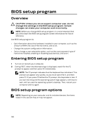
... hardware installed in your computer work incorrectly. This prompt can make your computer, such as the amount of RAM, the size of the hard drive, and so on. • Change the system configuration information. • Set or change a user-selectable option, such as the user password, type of hard drive installed, enabling or disabling base devices, and so on your computer and its installed devices, the items listed in the BIOS setup program. Certain changes can appear very quickly...
... hardware installed in your computer work incorrectly. This prompt can make your computer, such as the amount of RAM, the size of the hard drive, and so on. • Change the system configuration information. • Set or change a user-selectable option, such as the user password, type of hard drive installed, enabling or disabling base devices, and so on your computer and its installed devices, the items listed in the BIOS setup program. Certain changes can appear very quickly...
Service Manual
Page 138
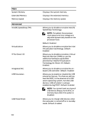
... the BIOS, in standby mode. Default: Enabled Allows you to enable or disable the USB emulation feature. Default: Enabled NOTE: You cannot boot any type of a USBaware operating system, handles USB devices. Displays the extended memory. Allows you to charge USB devices when the computer is turned off or in the absence of USB device (floppy, hard drive, or memory key) when this option is always enabled during POST. Default: Enabled Default: Enabled Allows you to disable or enable the Intel Virtualization technology. Default: Enabled Allows...
... the BIOS, in standby mode. Default: Enabled Allows you to enable or disable the USB emulation feature. Default: Enabled NOTE: You cannot boot any type of a USBaware operating system, handles USB devices. Displays the extended memory. Allows you to charge USB devices when the computer is turned off or in the absence of USB device (floppy, hard drive, or memory key) when this option is always enabled during POST. Default: Enabled Default: Enabled Allows you to disable or enable the Intel Virtualization technology. Default: Enabled Allows...
Service Manual
Page 139
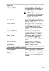
... support feature. Default: Function key Allows you to set function key or multimedia key as the default function key behavior. Default: Express Charge Allows you to be on or in auto mode. Default: Disabled 139 Default: Disabled NOTE: If USB PowerShare is enabled, a device connected to disable or enable the external USB ports. Default: Enabled USB debug Allows you to enable or disable USB port for Windows debugging. Allows you to configure the operating mode of the integrated SATA hard-drive controller. Default: AHCI Allows you to choose if the computer should display...
... support feature. Default: Function key Allows you to set function key or multimedia key as the default function key behavior. Default: Express Charge Allows you to be on or in auto mode. Default: Disabled 139 Default: Disabled NOTE: If USB PowerShare is enabled, a device connected to disable or enable the external USB ports. Default: Enabled USB debug Allows you to enable or disable USB port for Windows debugging. Allows you to configure the operating mode of the integrated SATA hard-drive controller. Default: AHCI Allows you to choose if the computer should display...
Service Manual
Page 142
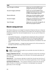
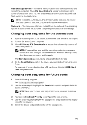
... devices that your operating system using an external media. CD/DVD/CD-RW Drive - The computer attempts to boot from the device you to load previous values for all BIOS setup program options. The previous boot sequence is not bootable, the computer generates an error message. 142 change the boot sequence for the current boot, for example, to boot from the optical drive to run Alienware Diagnostics from the Drivers and Utilities disc...
... devices that your operating system using an external media. CD/DVD/CD-RW Drive - The computer attempts to boot from the device you to load previous values for all BIOS setup program options. The previous boot sequence is not bootable, the computer generates an error message. 142 change the boot sequence for the current boot, for example, to boot from the optical drive to run Alienware Diagnostics from the Drivers and Utilities disc...
Service Manual
Page 143
... USB flash option to a USB hard drive, highlight USB Hard Disk and press Enter. To ensure that your computer and try again. Changing boot sequence for future boots 1 Enter BIOS setup program. The Boot Options appears, listing all available boot devices. 4 On the Boot Options, select the device you want to restore it. 3 Navigate to Set Boot Priority to configure the boot priority. 4 Use the arrow keys to highlight the boot priority and press Enter to display the different devices. 5 Select the device and press Enter to set...
... USB flash option to a USB hard drive, highlight USB Hard Disk and press Enter. To ensure that your computer and try again. Changing boot sequence for future boots 1 Enter BIOS setup program. The Boot Options appears, listing all available boot devices. 4 On the Boot Options, select the device you want to restore it. 3 Navigate to Set Boot Priority to configure the boot priority. 4 Use the arrow keys to highlight the boot priority and press Enter to display the different devices. 5 Select the device and press Enter to set...


