Owner's Manual
Page 7
...Before You Begin 71 Recommended Tools 71 Turning Off Your Computer 71 Before Working Inside Your Computer 72 Memory 73 Modem 75 Mini PCI Card 76 11 Appendix Specifications 81 Using the System Setup Program 86 Overview 86 Viewing the System Setup Screens 87 ...System Setup Screens 87 Commonly Used Options 87 Dell Technical Support Policy (U.S. Only 88 Definition of "Dell-Installed" Software and Peripherals 89 Definition of "Third-Party" Software and Peripherals 89 Contacting Dell 89 Macrovision Product Notice 107 FCC Notices (U.S. Only 107 Class A ...
...Before You Begin 71 Recommended Tools 71 Turning Off Your Computer 71 Before Working Inside Your Computer 72 Memory 73 Modem 75 Mini PCI Card 76 11 Appendix Specifications 81 Using the System Setup Program 86 Overview 86 Viewing the System Setup Screens 87 ...System Setup Screens 87 Commonly Used Options 87 Dell Technical Support Policy (U.S. Only 88 Definition of "Dell-Installed" Software and Peripherals 89 Definition of "Third-Party" Software and Peripherals 89 Contacting Dell 89 Macrovision Product Notice 107 FCC Notices (U.S. Only 107 Class A ...
Owner's Manual
Page 20
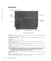
... outlet. M E M O R Y M O D U L E C O V E R - Stores software and data. B A T T E R Y / B A T T E R Y B A Y - M I N I P C I R V E N T - www.dell.com | support.dell.com Bottom View Mini PCI card and modem cover memory module cover air vent module bay module bay latch release battery* battery latch release hard drive cover *optional 8-cell ... A S E - See "Using a Battery" on page 29 for instructions. Covers the compartment that contains the Mini PCI card and modem. Covers the compartment that contains the memory module. The computer uses an internal fan to accumulate...
... outlet. M E M O R Y M O D U L E C O V E R - Stores software and data. B A T T E R Y / B A T T E R Y B A Y - M I N I P C I R V E N T - www.dell.com | support.dell.com Bottom View Mini PCI card and modem cover memory module cover air vent module bay module bay latch release battery* battery latch release hard drive cover *optional 8-cell ... A S E - See "Using a Battery" on page 29 for instructions. Covers the compartment that contains the Mini PCI card and modem. Covers the compartment that contains the memory module. The computer uses an internal fan to accumulate...
Owner's Manual
Page 75
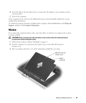
...: Before you begin any of memory installed in "Before You Begin" on page 71. 2 Turn the computer over and loosen the captive screws on the Mini PCI card and modem cover. 3 Place your computer and an electrical outlet. 7 Turn on the computer...
...: Before you begin any of memory installed in "Before You Begin" on page 71. 2 Turn the computer over and loosen the captive screws on the Mini PCI card and modem cover. 3 Place your computer and an electrical outlet. 7 Turn on the computer...

Owner's Manual
Page 76
... card with the screw holes and press the modem into the connector on the system board, and disconnect the modem cable. Mini PCI Card NOTE: 2.4-GHz Mini PCI cards may be removed and installed by the user. If you feel resistance, check the connectors and realign the card. 6 Align the... modem with your computer, the card is not already installed, go to ensure correct insertion. www.dell.com | support.dell.com 4 If a modem is ...
... card with the screw holes and press the modem into the connector on the system board, and disconnect the modem cable. Mini PCI Card NOTE: 2.4-GHz Mini PCI cards may be removed and installed by the user. If you feel resistance, check the connectors and realign the card. 6 Align the... modem with your computer, the card is not already installed, go to ensure correct insertion. www.dell.com | support.dell.com 4 If a modem is ...

Owner's Manual
Page 77
Mini PCI card and modem cover captive screws (2) antenna cables Adding and Replacing Parts 77 CAUTION: Before you begin any of the procedures in this section, follow the safety instructions located in the Product Information Guide. 1 Follow the procedures in "Before You Begin" on page 71. 2 Turn the computer over. 3 Loosen the captive screws on the cover, and remove the cover.
Mini PCI card and modem cover captive screws (2) antenna cables Adding and Replacing Parts 77 CAUTION: Before you begin any of the procedures in this section, follow the safety instructions located in the Product Information Guide. 1 Follow the procedures in "Before You Begin" on page 71. 2 Turn the computer over. 3 Loosen the captive screws on the cover, and remove the cover.

Owner's Manual
Page 78
c Lift the Mini PCI card out of its connector. securing tabs (2) NOTICE: The connectors are replacing a Mini PCI card, remove the existing card: a Disconnect the Mini PCI card from any attached cables. b Release the Mini PCI card by spreading the metal securing tabs until the card pops up slightly. If you are keyed to step 5. If you feel resistance, check the connectors and realign the card. 78 Adding and Replacing Parts www.dell.com | support.dell.com 4 If a Mini PCI card is not already installed, go to ensure correct insertion.
c Lift the Mini PCI card out of its connector. securing tabs (2) NOTICE: The connectors are replacing a Mini PCI card, remove the existing card: a Disconnect the Mini PCI card from any attached cables. b Release the Mini PCI card by spreading the metal securing tabs until the card pops up slightly. If you are keyed to step 5. If you feel resistance, check the connectors and realign the card. 78 Adding and Replacing Parts www.dell.com | support.dell.com 4 If a Mini PCI card is not already installed, go to ensure correct insertion.

Owner's Manual
Page 79
antenna cables 7 Replace the cover and tighten the screws. NOTICE: To avoid damaging the Mini PCI card, never place cables on top of or under the card. 6 Connect the antenna cables to the connectors on the Mini PCI card. Adding and Replacing Parts 79 5 Align the Mini PCI card with the connector at a 45-degree angle, and press the Mini PCI card into the connector until you hear a click.
antenna cables 7 Replace the cover and tighten the screws. NOTICE: To avoid damaging the Mini PCI card, never place cables on top of or under the card. 6 Connect the antenna cables to the connectors on the Mini PCI card. Adding and Replacing Parts 79 5 Align the Mini PCI card with the connector at a 45-degree angle, and press the Mini PCI card into the connector until you hear a click.

Owner's Manual
Page 82
... 64-MB shared memory LVDS NTSC or PAL in S-video mode 82 Appendix www.dell.com | support.dell.com Ports and Connectors Video Audio USB (2) Modem Network adapter IEEE 1394 S-video TV-out Mini PCI Secure Digital Communications Modem: Type Controller Interface Network adapter Wireless Video Video type Video... microphone connector, stereo headphone/speakers connector 4-pin USB 2.0-compliant connector RJ-11 port RJ-45 port 4-pin serial connector 7-pin mini-DIN connector Type IIIA Mini PCI card slot SD slot v.92 56K MDC softmodem internal AC'97 bus 10/100 EthernetLAN on system board internal...
... 64-MB shared memory LVDS NTSC or PAL in S-video mode 82 Appendix www.dell.com | support.dell.com Ports and Connectors Video Audio USB (2) Modem Network adapter IEEE 1394 S-video TV-out Mini PCI Secure Digital Communications Modem: Type Controller Interface Network adapter Wireless Video Video type Video... microphone connector, stereo headphone/speakers connector 4-pin USB 2.0-compliant connector RJ-11 port RJ-45 port 4-pin serial connector 7-pin mini-DIN connector Type IIIA Mini PCI card slot SD slot v.92 56K MDC softmodem internal AC'97 bus 10/100 EthernetLAN on system board internal...

Owner's Manual
Page 110
... slot, 17 F fan description, 16 system view, 16 Finding Informationdocumentati on, 9 H hard drive description, 20 problems, 56 system view, 20 hardware conflicts, 51 Dell Diagnostics, 47 Hardware Troubleshooter, 51 Help and Support Center, 12 help file, 9 I IEEE 1394 connector description, 14 problems, 59 system view, 14 installing parts before... Tag, 10 M memory adding, 73 removing, 74 memory module cover description, 20 system view, 20 messages error, 56, 58 Microsoft Windows label, 10 Mini PCI card installing, 76 Mini PCI card and modem cover description, 20 system view, 20 110 Index
... slot, 17 F fan description, 16 system view, 16 Finding Informationdocumentati on, 9 H hard drive description, 20 problems, 56 system view, 20 hardware conflicts, 51 Dell Diagnostics, 47 Hardware Troubleshooter, 51 Help and Support Center, 12 help file, 9 I IEEE 1394 connector description, 14 problems, 59 system view, 14 installing parts before... Tag, 10 M memory adding, 73 removing, 74 memory module cover description, 20 system view, 20 messages error, 56, 58 Microsoft Windows label, 10 Mini PCI card installing, 76 Mini PCI card and modem cover description, 20 system view, 20 110 Index


