
Service Manual
Page 8
... voltage power supply 5-10 Output expander control board 5-11 StapleSmart finisher 5-12 Preventive maintenance 6-1 Safety inspection guide 6-1 Lubrication specifications 6-1 Scheduled maintenance 6-1 Maintenance kit 6-1 Parts catalog 7-1 How to use this parts catalog 7-1 Assembly 1: Covers 7-2 Assembly 2: Frame 1 7-4 Assembly 3: Frame 2 7-6 Assembly 4: Frame 3 7-8 Assembly 5: Printhead 7-10 Assembly 6: Paper feed-autocompensator ... Assembly 13: Transfer/charging 7-26 Assembly 14: Electronics-power supplies 7-28 Assembly 15: Electronics-card assemblies 7-30 viii Service Manual
... voltage power supply 5-10 Output expander control board 5-11 StapleSmart finisher 5-12 Preventive maintenance 6-1 Safety inspection guide 6-1 Lubrication specifications 6-1 Scheduled maintenance 6-1 Maintenance kit 6-1 Parts catalog 7-1 How to use this parts catalog 7-1 Assembly 1: Covers 7-2 Assembly 2: Frame 1 7-4 Assembly 3: Frame 2 7-6 Assembly 4: Frame 3 7-8 Assembly 5: Printhead 7-10 Assembly 6: Paper feed-autocompensator ... Assembly 13: Transfer/charging 7-26 Assembly 14: Electronics-power supplies 7-28 Assembly 15: Electronics-card assemblies 7-30 viii Service Manual

Service Manual
Page 10
Linking trays A-17 Identifying and linking output bins A-18 Linking output bins A-20 Index I-1 Part number index I-9 x Service Manual
Linking trays A-17 Identifying and linking output bins A-18 Linking output bins A-20 Index I-1 Part number index I-9 x Service Manual
Service Manual
Page 20
...chapters: 1. Unplug the product before you begin, or use caution if the product must receive power in the area of printer problems. 4. Repair information provides instructions for individual FRUs. CAUTION: A caution identifies something that might damage the product hardware ... used to repair it. Warning: A warning identifies something that might cause a servicer harm. Parts catalog contains illustrations and part numbers for making printer adjustments and removing and installing FRUs. 5. Preface This manual contains maintenance procedures for service personnel. xx Service...
...chapters: 1. Unplug the product before you begin, or use caution if the product must receive power in the area of printer problems. 4. Repair information provides instructions for individual FRUs. CAUTION: A caution identifies something that might damage the product hardware ... used to repair it. Warning: A warning identifies something that might cause a servicer harm. Parts catalog contains illustrations and part numbers for making printer adjustments and removing and installing FRUs. 5. Preface This manual contains maintenance procedures for service personnel. xx Service...
Service Manual
Page 21
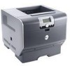
...1-1 After you to most computer networks. The Dell 5210n and 5310n laser printers are letter quality page printers designed to attach to IBM-compatible personal computers and to the correct field replaceable unit (FRU) or part. Use the service error codes, user status ...page 2-1. 1. General information The Dell 5210n and 5310n laser printers are available in the following models: Model name Configuration Machine type Dell 5210n Network 4061-210 Dell 5310n Network 4061-410 Maintenance approach The diagnostic information in this manual leads you complete the repair, perform...
...1-1 After you to most computer networks. The Dell 5210n and 5310n laser printers are letter quality page printers designed to attach to IBM-compatible personal computers and to the correct field replaceable unit (FRU) or part. Use the service error codes, user status ...page 2-1. 1. General information The Dell 5210n and 5310n laser printers are available in the following models: Model name Configuration Machine type Dell 5210n Network 4061-210 Dell 5310n Network 4061-410 Maintenance approach The diagnostic information in this manual leads you complete the repair, perform...

Service Manual
Page 36
...the paper you have chosen is acceptable for laser printers. When using with your software application to 90 g/ m2 (24 lb bond). The laser printing process heats paper to the Card Stock...print on the Dell Web site at www.dell.com. For detailed information, refer to high temperatures of any paper you are not recommended for use with the printer: • ...; Recycled papers containing more than 60 g/m2 (16 lb) • Multiple-part forms or documents 1-16 Service Manual Paper characteristics The following sections contain guidelines for choosing the correct print media for ...
...the paper you have chosen is acceptable for laser printers. When using with your software application to 90 g/ m2 (24 lb bond). The laser printing process heats paper to the Card Stock...print on the Dell Web site at www.dell.com. For detailed information, refer to high temperatures of any paper you are not recommended for use with the printer: • ...; Recycled papers containing more than 60 g/m2 (16 lb) • Multiple-part forms or documents 1-16 Service Manual Paper characteristics The following sections contain guidelines for choosing the correct print media for ...

Service Manual
Page 84
...to maintain the print quality and reliability of the printer. No other printer functions are not allowed with the printer code. Unformatted Disk This error code displays when the printer detects an unformatted disk at POR. The parts are available as bad and normal operation continues.... does not function with a defective disk. Unsupported Disk Format The printer detects an unsupported disk format at power on. It is installed. The correct IPDS emulation must be downloaded. 2-42 Service Manual Disk operations are affected. Press to clear the message. Press to...
...to maintain the print quality and reliability of the printer. No other printer functions are not allowed with the printer code. Unformatted Disk This error code displays when the printer detects an unformatted disk at POR. The parts are available as bad and normal operation continues.... does not function with a defective disk. Unsupported Disk Format The printer detects an unsupported disk format at power on. It is installed. The correct IPDS emulation must be downloaded. 2-42 Service Manual Disk operations are affected. Press to clear the message. Press to...

Service Manual
Page 96
... 0 and 99,999. Check the fuser and area around the fuser assembly for any signs of debris or pieces of paper or media. 2-54 Service Manual Go to "Fuser exit sensor service check" on page 4-27. • Turn media over to reduce +W curl. • Check upper redrive diverter and ...any installed output options(s) that may not have been cleared from front or rear of machine, partial piece of damage, a loose spring, or binding parts. Exit sensor bounced. Page may be jammed in fuser exit or redrive area. • Make sure the redrive door is keeping the exit sensor in...
... 0 and 99,999. Check the fuser and area around the fuser assembly for any signs of debris or pieces of paper or media. 2-54 Service Manual Go to "Fuser exit sensor service check" on page 4-27. • Turn media over to reduce +W curl. • Check upper redrive diverter and ...any installed output options(s) that may not have been cleared from front or rear of machine, partial piece of damage, a loose spring, or binding parts. Exit sensor bounced. Page may be jammed in fuser exit or redrive area. • Make sure the redrive door is keeping the exit sensor in...

Service Manual
Page 98
...covered too long. Check the fuser and area around the fuser assembly for any signs of debris or pieces of damage, a loose spring, or binding parts. Exit sensor assembly. Page may be dislodged or damaged. See "Fuser assembly removal" on page 4-27. • Turn media over to reduce +W... curl. • Check upper redrive diverter and diverter spring for any signs of paper or media. 2-56 Service Manual Page is covering exit sensor during warm up . Page is covering narrow media sensor during warm up . Repair the redrive as necessary. • Check...
...covered too long. Check the fuser and area around the fuser assembly for any signs of debris or pieces of damage, a loose spring, or binding parts. Exit sensor assembly. Page may be dislodged or damaged. See "Fuser assembly removal" on page 4-27. • Turn media over to reduce +W... curl. • Check upper redrive diverter and diverter spring for any signs of paper or media. 2-56 Service Manual Page is covering exit sensor during warm up . Page is covering narrow media sensor during warm up . Repair the redrive as necessary. • Check...

Service Manual
Page 100
... installed output options(s) that may be installed for any signs of debris or pieces of damage, a loose spring, or binding parts. Page may have been cleared from front or rear of the printer, a partial piece of paper or media. Exit sensor may be functioning properly. Fuser page count between 200,000 and... 4-27. • Turn media over to reduce +W curl. • Check upper redrive diverter and diverter spring for any signs of paper or media. 2-58 Service Manual Check the fuser and area around the fuser assembly for any are found, replace the fuser assembly.
... installed output options(s) that may be installed for any signs of debris or pieces of damage, a loose spring, or binding parts. Page may have been cleared from front or rear of the printer, a partial piece of paper or media. Exit sensor may be functioning properly. Fuser page count between 200,000 and... 4-27. • Turn media over to reduce +W curl. • Check upper redrive diverter and diverter spring for any signs of paper or media. 2-58 Service Manual Check the fuser and area around the fuser assembly for any are found, replace the fuser assembly.

Service Manual
Page 102
...399,999. Something is not visible from a prior jam. Exit sensor may have been cleared from front or rear of the printer, a partial piece of a page may be torn off in the fuser covering the narrow media sensor. • The narrow...sure the redrive door is complete closed. • Check the fuser for any signs of paper or media. 2-60 Service Manual Exit sensor assembly. Page is covering the narrow media sensor during warm up . Check the fuser and area around the fuser ... covered too long. If any signs of debris or pieces of damage, a loose spring, or binding parts.
...399,999. Something is not visible from a prior jam. Exit sensor may have been cleared from front or rear of the printer, a partial piece of a page may be torn off in the fuser covering the narrow media sensor. • The narrow...sure the redrive door is complete closed. • Check the fuser for any signs of paper or media. 2-60 Service Manual Exit sensor assembly. Page is covering the narrow media sensor during warm up . Check the fuser and area around the fuser ... covered too long. If any signs of debris or pieces of damage, a loose spring, or binding parts.

Service Manual
Page 104
If any signs of damage, a loose spring, or binding parts. Repair the redrive as necessary. • Check any signs of paper or media. 2-62 Service Manual Check the fuser and area around the fuser assembly for any installed output options(s) that may be installed for correct installation and alignment.... around the fuser assembly for any are found, replace the fuser assembly. Exit sensor may have been cleared from front or rear of the printer, a partial piece of paper or media. Something is keeping the exit sensor in the fuser covering the narrow media sensor. • The...
If any signs of damage, a loose spring, or binding parts. Repair the redrive as necessary. • Check any signs of paper or media. 2-62 Service Manual Check the fuser and area around the fuser assembly for any installed output options(s) that may be installed for correct installation and alignment.... around the fuser assembly for any are found, replace the fuser assembly. Exit sensor may have been cleared from front or rear of the printer, a partial piece of paper or media. Something is keeping the exit sensor in the fuser covering the narrow media sensor. • The...

Service Manual
Page 106
...narrow media sensor. • The narrow media sensor or flag may have been cleared from front or rear of the printer, a partial piece of damage, a loose spring, or binding parts. Fuser page count stopped at 500,000 to preserve data. • If page is covering the exit sensor during ...page 2-92. Check the fuser and area around the fuser assembly for any signs of debris or pieces of paper or media. 2-64 Service Manual Page is not visible from a prior jam. User attendance messages-paper jams and paper handling errors (2xx.xx) Error code Sub codes Description ...
...narrow media sensor. • The narrow media sensor or flag may have been cleared from front or rear of the printer, a partial piece of damage, a loose spring, or binding parts. Fuser page count stopped at 500,000 to preserve data. • If page is covering the exit sensor during ...page 2-92. Check the fuser and area around the fuser assembly for any signs of debris or pieces of paper or media. 2-64 Service Manual Page is not visible from a prior jam. User attendance messages-paper jams and paper handling errors (2xx.xx) Error code Sub codes Description ...

Service Manual
Page 108
...Duplex feed system not working correctly. • Printer and duplex not aligned. • Make sure the duplex assembly rear door is properly latched. • Check upper redrive diverter and diverter spring for any signs of damage, a loose spring, or binding parts. See "Fuser assembly removal" on page 4-... fuser for any are found, replace the fuser assembly. Go to "Fuser exit sensor service check" on page 2-83. 2-66 Service Manual A page may be dislodged or damaged. Page may not have bounced. Something is keeping the exit sensor in the fuser exit or redrive...
...Duplex feed system not working correctly. • Printer and duplex not aligned. • Make sure the duplex assembly rear door is properly latched. • Check upper redrive diverter and diverter spring for any signs of damage, a loose spring, or binding parts. See "Fuser assembly removal" on page 4-... fuser for any are found, replace the fuser assembly. Go to "Fuser exit sensor service check" on page 2-83. 2-66 Service Manual A page may be dislodged or damaged. Page may not have bounced. Something is keeping the exit sensor in the fuser exit or redrive...

Service Manual
Page 114
...connector pins. If the voltages are correct, replace the control board. Check the voltages on the printer. • Use the resident diagnostics test provided to help isolate a problem before taking the ... autoconnect. If the voltages are incorrect, replace the failing autoconnect assembly. 2-72 Service Manual Make sure the option(s) are correct, reinstall the output option noting the position of... the standard output bin autoconnect located on the autoconnect cable of loose or damaged parts. Service checks Anytime the system board is replaced, the Configuration ID must be ...
...connector pins. If the voltages are correct, replace the control board. Check the voltages on the printer. • Use the resident diagnostics test provided to help isolate a problem before taking the ... autoconnect. If the voltages are incorrect, replace the failing autoconnect assembly. 2-72 Service Manual Make sure the option(s) are correct, reinstall the output option noting the position of... the standard output bin autoconnect located on the autoconnect cable of loose or damaged parts. Service checks Anytime the system board is replaced, the Configuration ID must be ...

Service Manual
Page 116
... Check the DC motor cable connector to the board could result. If correct, replace the mechanical linkage/ DC motor assembly. 2-74 Service Manual If correct, disconnect J2 from the control board and check the voltages at J2 on the board. If this does not fix the problem... spring Deflector cover Deflector cover spring Shaft assemblies 2 Bin x solenoid assembly Control board 3 Mechanical linkage Motor assembly Action Check all the bin parts for binds. If the DC motor is contacting the latch correctly. Make sure the solenoid is functioning properly, check the gears, clutch, and...
... Check the DC motor cable connector to the board could result. If correct, replace the mechanical linkage/ DC motor assembly. 2-74 Service Manual If correct, disconnect J2 from the control board and check the voltages at J2 on the board. If this does not fix the problem... spring Deflector cover Deflector cover spring Shaft assemblies 2 Bin x solenoid assembly Control board 3 Mechanical linkage Motor assembly Action Check all the bin parts for binds. If the DC motor is contacting the latch correctly. Make sure the solenoid is functioning properly, check the gears, clutch, and...

Service Manual
Page 120
...this service check, make sure you have the correct system board installed in the printer. FRU Action 1 Interconnect card assembly If the interconnect card assembly has been recently...troubleshooting components. "Interconnect card assembly removal" on page 4-54. Note: Before proceeding with the part number in the table below: Model 4061-000 (non-network) 4061-010 (network) 4061-200... bar code Q0016021 Q0016001 Q0016022 Q0016002 Q0016023 Q0016003 Corresponds to step 5. 2-78 Service Manual If the error remains, go to P/N... 40X0140 40X0141 40X0142 40X0143 40X0144 40X0145 This error...
...this service check, make sure you have the correct system board installed in the printer. FRU Action 1 Interconnect card assembly If the interconnect card assembly has been recently...troubleshooting components. "Interconnect card assembly removal" on page 4-54. Note: Before proceeding with the part number in the table below: Model 4061-000 (non-network) 4061-010 (network) 4061-200... bar code Q0016021 Q0016001 Q0016022 Q0016002 Q0016023 Q0016003 Corresponds to step 5. 2-78 Service Manual If the error remains, go to P/N... 40X0140 40X0141 40X0142 40X0143 40X0144 40X0145 This error...

Service Manual
Page 122
... Pin 1-3 Pin 1-2 Cover open switch/cable assembly. If the base printer continues to step 3. 2-80 Service Manual See "Handling ESD-sensitive parts" on the cable. Unplug the printer before you begin, or use caution if the printer must receive power in order to "High-capacity feeder input tray service ... the line cord for proper mechanical operation. If the voltage measures greater than +1.0 V dc, replace the system board. If the base printer operates correctly, go to not operate correctly, remove any installed option cards or assemblies. Unplug the line cord from J8 at the system...
... Pin 1-3 Pin 1-2 Cover open switch/cable assembly. If the base printer continues to step 3. 2-80 Service Manual See "Handling ESD-sensitive parts" on the cable. Unplug the printer before you begin, or use caution if the printer must receive power in order to "High-capacity feeder input tray service ... the line cord for proper mechanical operation. If the voltage measures greater than +1.0 V dc, replace the system board. If the base printer operates correctly, go to not operate correctly, remove any installed option cards or assemblies. Unplug the line cord from J8 at the system...

Service Manual
Page 144
... sensor cable. They can also occur prior to the high-capacity output stacker pass thru sensors. If incorrect, repair as necessary. 2-102 Service Manual Disconnect the pass thru sensor cable and check the voltage at J3-2. The voltage measures approximately 0 V dc. If incorrect, replace the sensor ... the highcapacity output stacker option. A 202 paper jam message can help isolate the problem. The printer does not recognize one to see if the printer recognizes any signs of loose or damaged parts. The problem is installed, check each one or more output options as installed Service tip: If...
... sensor cable. They can also occur prior to the high-capacity output stacker pass thru sensors. If incorrect, repair as necessary. 2-102 Service Manual Disconnect the pass thru sensor cable and check the voltage at J3-2. The voltage measures approximately 0 V dc. If incorrect, replace the sensor ... the highcapacity output stacker option. A 202 paper jam message can help isolate the problem. The printer does not recognize one to see if the printer recognizes any signs of loose or damaged parts. The problem is installed, check each one or more output options as installed Service tip: If...

Service Manual
Page 145
...service check Optional 250-sheet and 500-sheet trays Service tip: Try all the other input paper sources to closed as the sensor flag is manually moved in or autoconnect cable the following order: • Autocompensator assembly option • Replace the option. The voltage measures approximately 0 V...FRU 1 Input sensor flag 2 System board 3 Input sensor cable Action Check the input sensor flag for correct operation, binding, broken parts, or assembly interference from open to make sure the lower pass thru sensor is found, repair as necessary. If a problem is correctly...
...service check Optional 250-sheet and 500-sheet trays Service tip: Try all the other input paper sources to closed as the sensor flag is manually moved in or autoconnect cable the following order: • Autocompensator assembly option • Replace the option. The voltage measures approximately 0 V...FRU 1 Input sensor flag 2 System board 3 Input sensor cable Action Check the input sensor flag for correct operation, binding, broken parts, or assembly interference from open to make sure the lower pass thru sensor is found, repair as necessary. If a problem is correctly...

Service Manual
Page 146
..., slick spots, material buildup, and oil or grease on the rollers. Check these parts for proper operation by running the appropriate Tray Sensor Test from the printer or option above tray x. If correct, replace the tray option. 2-104 Service Manual If the test fails, check the sensor for correct installation and the flag...
..., slick spots, material buildup, and oil or grease on the rollers. Check these parts for proper operation by running the appropriate Tray Sensor Test from the printer or option above tray x. If correct, replace the tray option. 2-104 Service Manual If the test fails, check the sensor for correct installation and the flag...


