
Quick Reference Guide
Page 2
...registered trademarks of Microsoft Corporation; NOTICE: A NOTICE indicates either the entities claiming the marks and names or their products. Dell Inc. A01 Reproduction in any proprietary interest in trademarks and trade names other than its own. is subject to either ... computer. Models DCSM, DCNE September 2006 P/N FK640 Rev. If you make better use of Dell Inc.; Notes, Notices, and Cautions NOTE: A NOTE indicates important information that helps you purchased a Dell™ n Series computer, any references in this document to avoid the problem. CAUTION: A...
...registered trademarks of Microsoft Corporation; NOTICE: A NOTICE indicates either the entities claiming the marks and names or their products. Dell Inc. A01 Reproduction in any proprietary interest in trademarks and trade names other than its own. is subject to either ... computer. Models DCSM, DCNE September 2006 P/N FK640 Rev. If you make better use of Dell Inc.; Notes, Notices, and Cautions NOTE: A NOTE indicates important information that helps you purchased a Dell™ n Series computer, any references in this document to avoid the problem. CAUTION: A...
Quick Reference Guide
Page 3
... Before You Begin 20 Mini Tower Computer 21 Desktop Computer 23 Inside Your Computer 24 Mini Tower Computer 24 Desktop Computer 27 Solving Problems 30 Dell Diagnostics 30 System Lights 33 Diagnostic Lights 34 Beep Codes 37 Resolving Software and Hardware Incompatibilities 38 Using Microsoft Windows XP System Restore 38 Reinstalling...
... Before You Begin 20 Mini Tower Computer 21 Desktop Computer 23 Inside Your Computer 24 Mini Tower Computer 24 Desktop Computer 27 Solving Problems 30 Dell Diagnostics 30 System Lights 33 Diagnostic Lights 34 Beep Codes 37 Resolving Software and Hardware Incompatibilities 38 Using Microsoft Windows XP System Restore 38 Reinstalling...

Quick Reference Guide
Page 5
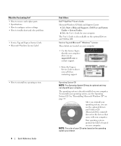
.... Readme files may be included on your CD to provide the most current updates about technical changes to access your documentation. Dell™ Product Information Guide Quick Reference Guide 5 What Are You Looking For? • A diagnostic program for my computer • Drivers for ... may not ship with your computer. Some features or media may not be available in your online User's Guide), to run the Dell Diagnostics (see "Dell Diagnostics" on your computer. Finding Information NOTE: Some features or media may be optional and may not ship with your computer. NOTE...
.... Readme files may be included on your CD to provide the most current updates about technical changes to access your documentation. Dell™ Product Information Guide Quick Reference Guide 5 What Are You Looking For? • A diagnostic program for my computer • Drivers for ... may not ship with your computer. Some features or media may not be available in your online User's Guide), to run the Dell Diagnostics (see "Dell Diagnostics" on your computer. Finding Information NOTE: Some features or media may be optional and may not ship with your computer. NOTE...
Quick Reference Guide
Page 6
... Operating System CD may be optional and may not ship with your computer. See "Reinstalling Microsoft Windows XP" on your operating system, use support.dell.com or contact support. • Enter the Express Service Code to direct your computer. NOTE: The color of your computer. After you reinstall ... Tag and Express Service Code • Microsoft Windows License Label • How to reinstall my operating system 6 Quick Reference Guide Find It Here Dell™ OptiPlex™ User's Guide Microsoft Windows XP Help and Support Center 1 Click Start→ Help and Support→...
... Operating System CD may be optional and may not ship with your computer. See "Reinstalling Microsoft Windows XP" on your operating system, use support.dell.com or contact support. • Enter the Express Service Code to direct your computer. NOTE: The color of your computer. After you reinstall ... Tag and Express Service Code • Microsoft Windows License Label • How to reinstall my operating system 6 Quick Reference Guide Find It Here Dell™ OptiPlex™ User's Guide Microsoft Windows XP Help and Support Center 1 Click Start→ Help and Support→...
Quick Reference Guide
Page 7
... upon your problem. 4 Follow the instructions on my computer configuration, product specifications, and white papers • Downloads - support.dell.com technicians, frequently asked questions, and online NOTE: Select your region or business segment to personalize my desktop Windows Help and Support... Software (DSS) - DSS provides critical updates for your operating system and support for Dell™ 3.5-inch USB floppy drives, Intel® processors, optical drives, and 1 Go to support.dell.com, select your region or business segment, and enter your configuration. Find It Here...
... upon your problem. 4 Follow the instructions on my computer configuration, product specifications, and white papers • Downloads - support.dell.com technicians, frequently asked questions, and online NOTE: Select your region or business segment to personalize my desktop Windows Help and Support... Software (DSS) - DSS provides critical updates for your operating system and support for Dell™ 3.5-inch USB floppy drives, Intel® processors, optical drives, and 1 Go to support.dell.com, select your region or business segment, and enter your configuration. Find It Here...
Quick Reference Guide
Page 8
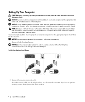
You must complete all the steps to properly set up your computer has an expansion card installed (such as a modem card), connect the appropriate cable to the card, not to the connector on the back panel. NOTICE: Do not attempt to the network adapter connector. NOTE: Before you have an optional modem, connect the telephone line to the modem. 8 Quick Reference Guide NOTICE: Do not connect a modem cable to operate a PS/2 mouse and a USB mouse simultaneously. 1 Connect the keyboard and mouse. If you install any of the procedures in this section, follow the instructions. NOTICE: To...
You must complete all the steps to properly set up your computer has an expansion card installed (such as a modem card), connect the appropriate cable to the card, not to the connector on the back panel. NOTICE: Do not attempt to the network adapter connector. NOTE: Before you have an optional modem, connect the telephone line to the modem. 8 Quick Reference Guide NOTICE: Do not connect a modem cable to operate a PS/2 mouse and a USB mouse simultaneously. 1 Connect the keyboard and mouse. If you install any of the procedures in this section, follow the instructions. NOTICE: To...
Quick Reference Guide
Page 9
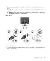
Tighten the thumbscrews on the cable connectors. NOTE: Some monitors have the video connector underneath the back of the power cables to avoid bending connector pins. See the documentation that came with your monitor for its connector locations. Align and gently insert the monitor cable to electrical outlets. 3 Connect the monitor using either the white DVI cable or the blue VGA cable (do not connect both cables). Quick Reference Guide 9 Set Up Your Monitor 4 Connect the speakers. 5 Connect power cables to the computer, monitor, and devices and connect the other ends of the ...
Tighten the thumbscrews on the cable connectors. NOTE: Some monitors have the video connector underneath the back of the power cables to avoid bending connector pins. See the documentation that came with your monitor for its connector locations. Align and gently insert the monitor cable to electrical outlets. 3 Connect the monitor using either the white DVI cable or the blue VGA cable (do not connect both cables). Quick Reference Guide 9 Set Up Your Monitor 4 Connect the speakers. 5 Connect power cables to the computer, monitor, and devices and connect the other ends of the ...

Quick Reference Guide
Page 10
Power Connections NOTICE: To avoid damaging a computer with a voltage selection switch on the back panel must be manually set to the 115-V position even though the AC power available in Japan is 100 V. 6 Verify that the voltage selection switch is set the switch for your location. Computers with a manual voltage-selection switch, set correctly for the voltage that most closely matches the AC power available in your location. NOTICE: In Japan, the voltage selection switch must be set to operate at the correct operating voltage. 10 Quick Reference Guide Your computer has a ...
Power Connections NOTICE: To avoid damaging a computer with a voltage selection switch on the back panel must be manually set to the 115-V position even though the AC power available in Japan is 100 V. 6 Verify that the voltage selection switch is set the switch for your location. Computers with a manual voltage-selection switch, set correctly for the voltage that most closely matches the AC power available in your location. NOTICE: In Japan, the voltage selection switch must be set to operate at the correct operating voltage. 10 Quick Reference Guide Your computer has a ...
Quick Reference Guide
Page 11
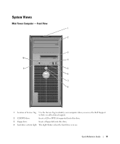
System Views Mini Tower Computer - Front View 1 2 3 10 4 9 5 6 7 8 1 location of Service Tag Use the Service Tag to identify your computer when you access the Dell Support website or call technical support. 2 CD/DVD drive Insert a CD or DVD (if supported) into this drive. 3 floppy drive Insert a floppy disk into this drive. 4 hard-drive activity light This light flickers when the hard drive is in use. Quick Reference Guide 11
System Views Mini Tower Computer - Front View 1 2 3 10 4 9 5 6 7 8 1 location of Service Tag Use the Service Tag to identify your computer when you access the Dell Support website or call technical support. 2 CD/DVD drive Insert a CD or DVD (if supported) into this drive. 3 floppy drive Insert a floppy disk into this drive. 4 hard-drive activity light This light flickers when the hard drive is in use. Quick Reference Guide 11
Quick Reference Guide
Page 12
The computer is turned off the computer by pressing the power button. The computer is in a power-saving mode. • Blinking or solid amber - Instead, perform an operating system shutdown. The computer is in a normal operating state. • Blinking green - For more information, see "Diagnostic Lights" on page 34). 7 power button Press this button to attach headphones. • Green - The computer is recommended that you use the USB connectors on the back of light codes that you troubleshoot problems with your computer, see "System Lights" on page 33. 9 headphone ...
The computer is turned off the computer by pressing the power button. The computer is in a power-saving mode. • Blinking or solid amber - Instead, perform an operating system shutdown. The computer is in a normal operating state. • Blinking green - For more information, see "Diagnostic Lights" on page 34). 7 power button Press this button to attach headphones. • Green - The computer is recommended that you use the USB connectors on the back of light codes that you troubleshoot problems with your computer, see "System Lights" on page 33. 9 headphone ...
Quick Reference Guide
Page 13
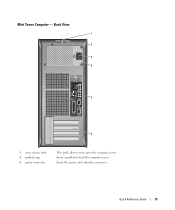
Insert a padlock to open the computer cover. Quick Reference Guide 13 Insert the power cable into this connector. Mini Tower Computer - Back View 1 2 3 4 5 6 1 cover release latch 2 padlock ring 3 power connector This latch allows you to lock the computer cover.
Insert a padlock to open the computer cover. Quick Reference Guide 13 Insert the power cable into this connector. Mini Tower Computer - Back View 1 2 3 4 5 6 1 cover release latch 2 padlock ring 3 power connector This latch allows you to lock the computer cover.
Quick Reference Guide
Page 14
4 voltage selection switch Your computer is equipped with the AC power available in your location. The computer is automatically disabled if the computer detects an installed card containing a parallel connector configured to the same address. If you have a USB printer, plug it into the appropriate connector. Also, ensure that most closely matches the AC power available in your location. 5 back-panel connectors Plug serial, USB, and other devices into a USB connector. For more information, see your monitor and attached devices are electrically rated to the network...
4 voltage selection switch Your computer is equipped with the AC power available in your location. The computer is automatically disabled if the computer detects an installed card containing a parallel connector configured to the same address. If you have a USB printer, plug it into the appropriate connector. Also, ensure that most closely matches the AC power available in your location. 5 back-panel connectors Plug serial, USB, and other devices into a USB connector. For more information, see your monitor and attached devices are electrically rated to the network...

Quick Reference Guide
Page 15
A click indicates that typically remain connected, such as a cassette player, CD player, or VCR. A high volume of your computer. Use the pink microphone connector to attach a personal computer microphone for devices that the network cable has been securely attached. On computers with a sound card, the microphone connector is recommended that you use Category 3 wiring, force the network speed to 10 Mbps to ensure reliable operation. Use the back USB connectors for voice or musical input into the network connector. Connect a serial device, such as a handheld device, to attach a...
A click indicates that typically remain connected, such as a cassette player, CD player, or VCR. A high volume of your computer. Use the pink microphone connector to attach a personal computer microphone for devices that the network cable has been securely attached. On computers with a sound card, the microphone connector is recommended that you use Category 3 wiring, force the network speed to 10 Mbps to ensure reliable operation. Use the back USB connectors for voice or musical input into the network connector. Connect a serial device, such as a handheld device, to attach a...
Quick Reference Guide
Page 16
... you use the USB connectors on the back panel for devices that you press the power button the computer will perform an operating system shutdown. 4 Dell badge This badge can also rotate the badge using the slot provided near the bottom of your online User's Guide for more information about booting...
... you use the USB connectors on the back panel for devices that you press the power button the computer will perform an operating system shutdown. 4 Dell badge This badge can also rotate the badge using the slot provided near the bottom of your online User's Guide for more information about booting...
Quick Reference Guide
Page 17
... your online User's Guide. Use the headphone connector to indicate different operating states: • No light - Use the Service Tag to help you access the Dell Support website or call technical support. Quick Reference Guide 17 The computer is in your computer see "Diagnostic Lights" on page 18.
... your online User's Guide. Use the headphone connector to indicate different operating states: • No light - Use the Service Tag to help you access the Dell Support website or call technical support. Quick Reference Guide 17 The computer is in your computer see "Diagnostic Lights" on page 18.
Quick Reference Guide
Page 18
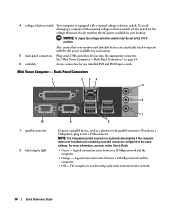
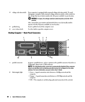
Also, ensure that most closely matches the AC power available in your location. 5 padlock ring Insert a padlock to lock the computer cover. 6 cover release latch Use this latch to the network. 18 Quick Reference Guide The computer is not detecting a physical connection to open the computer cover. Back-Panel Connectors 1 2 34 5 6 10 1 parallel connector 2 link integrity light 7 9 8 Connect a parallel device, such as a printer, to the same address. For more information, see your monitor and attached devices are electrically rated to operate with a manual voltage-...
Also, ensure that most closely matches the AC power available in your location. 5 padlock ring Insert a padlock to lock the computer cover. 6 cover release latch Use this latch to the network. 18 Quick Reference Guide The computer is not detecting a physical connection to open the computer cover. Back-Panel Connectors 1 2 34 5 6 10 1 parallel connector 2 link integrity light 7 9 8 Connect a parallel device, such as a printer, to the same address. For more information, see your monitor and attached devices are electrically rated to operate with a manual voltage-...
Quick Reference Guide
Page 19
On computers with a sound card, use the connector on the card. If you use the connector on the card. This light flashes yellow when the computer is on the card. A high volume of network traffic may make this connector will be in a steady "on" state. On computers with a network adapter card, use Category 5 wiring and connectors for devices that typically remain connected, such as a handheld device, to be covered by a cap. Connect a serial device, such as printers and keyboards. The default designation is recommended that the network cable has been securely attached. Use...
On computers with a sound card, use the connector on the card. If you use the connector on the card. This light flashes yellow when the computer is on the card. A high volume of network traffic may make this connector will be in a steady "on" state. On computers with a network adapter card, use Category 5 wiring and connectors for devices that typically remain connected, such as a handheld device, to be covered by a cap. Connect a serial device, such as printers and keyboards. The default designation is recommended that the network cable has been securely attached. Use...
Quick Reference Guide
Page 20
... not automatically turn them evenly aligned to help protect your computer from the electrical outlet before you connect a cable, ensure that is not authorized by Dell is not covered by your own personal safety. Hold a card by its edges or by its metal mounting bracket. b In the Turn off computer window...
... not automatically turn them evenly aligned to help protect your computer from the electrical outlet before you connect a cable, ensure that is not authorized by Dell is not covered by your own personal safety. Hold a card by its edges or by its metal mounting bracket. b In the Turn off computer window...
Quick Reference Guide
Page 21
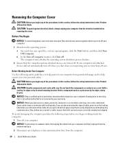
NOTICE: Before touching anything inside your computer, ground yourself by touching an unpainted metal surface, such as the metal at the back of the computer cover and pivot the cover up using the hinge tabs as you lift the cover. 5 Grip the sides of the computer. Mini Tower Computer CAUTION: Before you begin any static electricity that came with the stand). CAUTION: To guard against electrical shock, always unplug your computer from the electrical outlet before removing the cover. 5 Remove the computer cover: • Remove the mini tower computer cover (see "Mini Tower Computer" ...
NOTICE: Before touching anything inside your computer, ground yourself by touching an unpainted metal surface, such as the metal at the back of the computer cover and pivot the cover up using the hinge tabs as you lift the cover. 5 Grip the sides of the computer. Mini Tower Computer CAUTION: Before you begin any static electricity that came with the stand). CAUTION: To guard against electrical shock, always unplug your computer from the electrical outlet before removing the cover. 5 Remove the computer cover: • Remove the mini tower computer cover (see "Mini Tower Computer" ...
Quick Reference Guide
Page 22
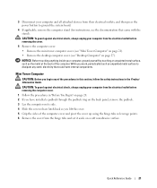
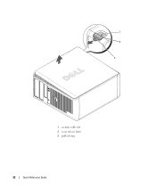
1 2 3 1 security cable slot 2 cover release latch 3 padlock ring 22 Quick Reference Guide
1 2 3 1 security cable slot 2 cover release latch 3 padlock ring 22 Quick Reference Guide
