User Manual
Page 9
... Requiring AP Authentication 76 Figure 37. MAC Access Control 86 Figure 38. VAP Settings 93 Figure 40. List of Figures List of DWS-3024/DWS-3024L 43 Figure 18. Rear panel view of Figures Figure 1. Fasten Mounting Brackets to the Wireless Client 98 Figure 43. Mounting the Switch ... Network Settings 95 Figure 41. Peer Unified Switch with optional DEM-410X module installed 49 Figure 27. D-Link Unified Access System Components 34 Figure 8. LED Indicators on DWS-3024 41 Figure 16. L3 Discovery Example 1 62 Figure 34. Networks Available to Switch 45 Figure 21. ...
... Requiring AP Authentication 76 Figure 37. MAC Access Control 86 Figure 38. VAP Settings 93 Figure 40. List of Figures List of DWS-3024/DWS-3024L 43 Figure 18. Rear panel view of Figures Figure 1. Fasten Mounting Brackets to the Wireless Client 98 Figure 43. Mounting the Switch ... Network Settings 95 Figure 41. Peer Unified Switch with optional DEM-410X module installed 49 Figure 27. D-Link Unified Access System Components 34 Figure 8. LED Indicators on DWS-3024 41 Figure 16. L3 Discovery Example 1 62 Figure 34. Networks Available to Switch 45 Figure 21. ...
User Manual
Page 21
... information about APs and their associated wireless clients. The switch tracks the status and statistics for end users. The DWS-3024L Unified Switch can manage up to 24 D-Link Access Points, whereas the DWS-3024 and the DWS-3026 switches can configure up to 512 associated wireless clients (256 per radio). You can manage up to...
... information about APs and their associated wireless clients. The switch tracks the status and statistics for end users. The DWS-3024L Unified Switch can manage up to 24 D-Link Access Points, whereas the DWS-3024 and the DWS-3026 switches can configure up to 512 associated wireless clients (256 per radio). You can manage up to...
User Manual
Page 22
...8500AP operates in IEEE 802.11a mode. The DWS-3024L manages up to 24 access points (APs), and the DWS-3024 and DWS-3026 switches manage up to eight virtual access points (VAPs) on the AP are disabled. In Standalone Mode, the D-Link Access Point acts as an individual access point... (CLI). If you start out with the following D-Link switches: • DWS-3024 (24 GE ports) • DWS-3024L (24 GE ports) • DWS-3026 (24 GE ports + 2 10G ports) D-Link Access Point The D-Link Access Point can operate in one of the D-Link Unified Access System, and you can easily transition the ...
...8500AP operates in IEEE 802.11a mode. The DWS-3024L manages up to 24 access points (APs), and the DWS-3024 and DWS-3026 switches manage up to eight virtual access points (VAPs) on the AP are disabled. In Standalone Mode, the D-Link Access Point acts as an individual access point... (CLI). If you start out with the following D-Link switches: • DWS-3024 (24 GE ports) • DWS-3024L (24 GE ports) • DWS-3026 (24 GE ports + 2 10G ports) D-Link Access Point The D-Link Access Point can operate in one of the D-Link Unified Access System, and you can easily transition the ...
User Manual
Page 25
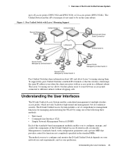
...Layer 3 roaming service allows wireless phone users to roam between access points connected to 48 access points (DWS-3024 and DWS-3026) or 24 access points (DWS-3024L). The D-Link Unified Access System includes a set of comprehensive management functions for functions not completely specified in a different...: • Web-based • Command-Line Interface (CLI) • Simple Network Management Protocol (SNMP) Each of the D-Link Unified Access System locally or remotely. Peer Unified Switch with Layer 3 Roaming Support Unified Switch 1 Remote Management Station Unified Switch 2...
...Layer 3 roaming service allows wireless phone users to roam between access points connected to 48 access points (DWS-3024 and DWS-3026) or 24 access points (DWS-3024L). The D-Link Unified Access System includes a set of comprehensive management functions for functions not completely specified in a different...: • Web-based • Command-Line Interface (CLI) • Simple Network Management Protocol (SNMP) Each of the D-Link Unified Access System locally or remotely. Peer Unified Switch with Layer 3 Roaming Support Unified Switch 1 Remote Management Station Unified Switch 2...
User Manual
Page 31
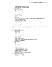
Peer-to 24 APs (DWS-3024L) or 48 APs (DWS-3024 and DWS-3026) per radio. Rogue Client detection - SYSLOG - The following list shows some of the D-Link Unified Access System - IEEE 802.1X - 2001 Port Based Network Access Control - Load Balancing - CLI Management (SSH) - Rogue ... IEEE Standards - SNMP v1, v2c, v3 - Web Management (SSL support) - IEEE 802.11d - IEEE 802.11g - Transmit Power Control - D-Link WLAN Private MIB • Simultaneous AP upgrade • Centralized data forwarding via tunneling for fast roaming and unified QoS • AP RF Monitoring •...
Peer-to 24 APs (DWS-3024L) or 48 APs (DWS-3024 and DWS-3026) per radio. Rogue Client detection - SYSLOG - The following list shows some of the D-Link Unified Access System - IEEE 802.1X - 2001 Port Based Network Access Control - Load Balancing - CLI Management (SSH) - Rogue ... IEEE Standards - SNMP v1, v2c, v3 - Web Management (SSL support) - IEEE 802.11d - IEEE 802.11g - Transmit Power Control - D-Link WLAN Private MIB • Simultaneous AP upgrade • Centralized data forwarding via tunneling for fast roaming and unified QoS • AP RF Monitoring •...
User Manual
Page 39
LED Indicators - Hardware Overview 39 Front Panel Components - Package Contents - Installing the Switch in a Rack - The DWS-3024/DWS-3024L and DWS-3026 have slightly different front and back panels based on the switch. The following sections describe this installation process: • Hardware Overview - Side Panels • ... - Connecting to the Network - Connecting to the External Redundant Power System • Connecting the Switch - 3 Installing the Hardware This chapter provides instructions for installing the D-Link DWS-3024, DWS-3024L, and DWS-3026 switch hardware.
LED Indicators - Hardware Overview 39 Front Panel Components - Package Contents - Installing the Switch in a Rack - The DWS-3024/DWS-3024L and DWS-3026 have slightly different front and back panels based on the switch. The following sections describe this installation process: • Hardware Overview - Side Panels • ... - Connecting to the Network - Connecting to the External Redundant Power System • Connecting the Switch - 3 Installing the Hardware This chapter provides instructions for installing the D-Link DWS-3024, DWS-3024L, and DWS-3026 switch hardware.
User Manual
Page 40
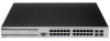
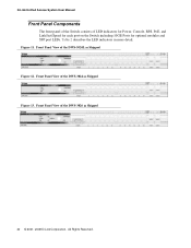
Figure 11. Front Panel View of the DWS-3026 as Shipped Figure 13. Front Panel View of the DWS-3024 as Shipped 40 © 2001- 2008 D-Link Corporation. All Rights Reserved. Front Panel View of LED indicators for Power, Console, RPS, PoE, and Link/Act/Speed for each port on the Switch including 10GE Ports for optional modules and SFP port LEDs. Table 2 describes the LED indicators in more detail. D-Link Unified Access System User Manual Front Panel Components The front panel of the Switch consists of the DWS-3024L as Shipped Figure 12.
Figure 11. Front Panel View of the DWS-3026 as Shipped Figure 13. Front Panel View of the DWS-3024 as Shipped 40 © 2001- 2008 D-Link Corporation. All Rights Reserved. Front Panel View of LED indicators for Power, Console, RPS, PoE, and Link/Act/Speed for each port on the Switch including 10GE Ports for optional modules and SFP port LEDs. Table 2 describes the LED indicators in more detail. D-Link Unified Access System User Manual Front Panel Components The front panel of the Switch consists of the DWS-3024L as Shipped Figure 12.
User Manual
Page 43
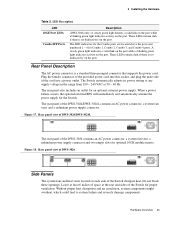
Plug the female connector of the provided power cord into this socket, and plug the male side of the DWS-3024/DWS-3024L contains an AC power connector, a system fan vent, and a redundant power supply connector. When a power failure occurs, the optional external RPS will immediately ... three-pronged connector that supports the power cord. Rear Panel Description The AC power connector is no link/activity on the port. The rear panel of the cord into a power outlet. Rear panel view of DWS-3024/DWS-3024L The rear panel of space at 50 ~ 60 Hz. Leave at least 6 inches of the...
Plug the female connector of the provided power cord into this socket, and plug the male side of the DWS-3024/DWS-3024L contains an AC power connector, a system fan vent, and a redundant power supply connector. When a power failure occurs, the optional external RPS will immediately ... three-pronged connector that supports the power cord. Rear Panel Description The AC power connector is no link/activity on the port. The rear panel of the cord into a power outlet. Rear panel view of DWS-3024/DWS-3024L The rear panel of space at 50 ~ 60 Hz. Leave at least 6 inches of the...


