User Guide
Page 7
... installing the DSS-24 on the DSS-24. Chapter 3, Connecting the DSS-24 to the DSS-24 10/100 Auto Negotiation Switch as the DSS-24. Appendix A, DSS-24 Technical Specifications, covers the technical specifications of the DSS-24. About This Guide 1 Organization Chapter 1, Introduction, gives and physical a functional overview of the DSS-24. All the information you need to other D-Link products is contained in general. DSS-24 10...
... installing the DSS-24 on the DSS-24. Chapter 3, Connecting the DSS-24 to the DSS-24 10/100 Auto Negotiation Switch as the DSS-24. Appendix A, DSS-24 Technical Specifications, covers the technical specifications of the DSS-24. About This Guide 1 Organization Chapter 1, Introduction, gives and physical a functional overview of the DSS-24. All the information you need to other D-Link products is contained in general. DSS-24 10...
User Guide
Page 8
...is divided into several sections. The topics covered are: • Summary of Features • Explanation of the DSS-24. DSS-24 10/100 Auto Negotiation Switch User's Guide 1 Introduction This chapter gives a physical and functional overview of Front and Rear Panels • Management Features ...DSS-24 has the following features: • 24 NWAY 10/100-TX Fast Ethernet Ports. • All ports support both Full Duplex and Half Duplex operation and are configurable with polarity detection and correcting. • Wire speed packet filtering and forwarding. • Per port LED to indicate link...
...is divided into several sections. The topics covered are: • Summary of Features • Explanation of the DSS-24. DSS-24 10/100 Auto Negotiation Switch User's Guide 1 Introduction This chapter gives a physical and functional overview of Front and Rear Panels • Management Features ...DSS-24 has the following features: • 24 NWAY 10/100-TX Fast Ethernet Ports. • All ports support both Full Duplex and Half Duplex operation and are configurable with polarity detection and correcting. • Wire speed packet filtering and forwarding. • Per port LED to indicate link...
User Guide
Page 9
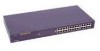
... the ports can be used to connect to switches and hubs that a port is working. Power Link/ Act/ Collision LEDS MDI-II Uplink Port MDI-X Ports DSS-24 Power 10/100 Fast Ethernet Switch Switch II Link/ 100 Mbps/ Collision 10 Mbps 1 234 56 7 9 10 11 12 Link/ 100 Mbps/ D-Link Collision 10 Mbps 13 14 15 17 18...
... the ports can be used to connect to switches and hubs that a port is working. Power Link/ Act/ Collision LEDS MDI-II Uplink Port MDI-X Ports DSS-24 Power 10/100 Fast Ethernet Switch Switch II Link/ 100 Mbps/ Collision 10 Mbps 1 234 56 7 9 10 11 12 Link/ 100 Mbps/ D-Link Collision 10 Mbps 13 14 15 17 18...
User Guide
Page 17
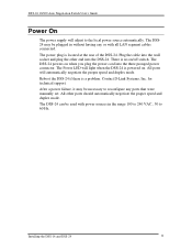
...DSS-24 can be necessary to the local power source automatically. DSS-24 10/100 Auto Negotiation Switch User's Guide Power On The power supply will light when the DSS-24... is powered on. There is a problem. The Power LED will adjust to reconfigure any or with power sources in without having any ports that were manually set. Installing the DSS-16 and DSS-24 11 Reboot the DSS-24...is located at the rear of the DSS-24. The DSS-24 powers on /off switch. Plug the cable into the wall ...
...DSS-24 can be necessary to the local power source automatically. DSS-24 10/100 Auto Negotiation Switch User's Guide Power On The power supply will light when the DSS-24... is powered on. There is a problem. The Power LED will adjust to reconfigure any or with power sources in without having any ports that were manually set. Installing the DSS-16 and DSS-24 11 Reboot the DSS-24...is located at the rear of the DSS-24. The DSS-24 powers on /off switch. Plug the cable into the wall ...
User Guide
Page 22
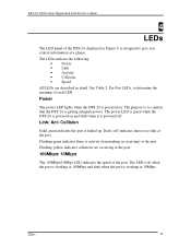
... powered on and dark when it is powered off ) indicates there is powered on . The power LED is green when the DSS-24 is no link at the port. LEDs 16 Dark (off . Flashing yellow indicates collisions are described in Figure 9, is getting adequate power. The LEDs indicate the following: • ... when the port is working at 100Mbps and dark when the port is to determine the meaning of the port. Flashing green indicates there is linked up. DSS-24 10/100 Auto Negotiation Switch User's Guide 4 LEDs The LED panel of the...
... powered on and dark when it is powered off ) indicates there is powered on . The power LED is green when the DSS-24 is no link at the port. LEDs 16 Dark (off . Flashing yellow indicates collisions are described in Figure 9, is getting adequate power. The LEDs indicate the following: • ... when the port is working at 100Mbps and dark when the port is to determine the meaning of the port. Flashing green indicates there is linked up. DSS-24 10/100 Auto Negotiation Switch User's Guide 4 LEDs The LED panel of the...
User Guide
Page 23
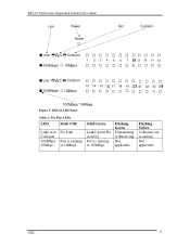
DSS-24 10/100 Auto Negotiation Switch User's Guide Link Power Power Act Collision Link/ 100Mbps/ Collision 10Mbps 1 234 56 7 9 10 11 12 Link/ 100Mbps/ Collision 10Mbps 13 14 15 17 18 19 21 22 23 100Mbps/ 10Mbps Figure 9: DSS-24 LED Panel Table 2: Per Port LEDs LED Dark (Off) Link/ Act/ Collision 100Mbps/ 10Mbps No Link Port is running at 10Mbps Solid Green Link Up but No Activity Port is running at 100Mbps Flashing Green Transmitting or Receiving Not applicable Flashing Yellow Collisions are occurring Not applicable LEDs 17
DSS-24 10/100 Auto Negotiation Switch User's Guide Link Power Power Act Collision Link/ 100Mbps/ Collision 10Mbps 1 234 56 7 9 10 11 12 Link/ 100Mbps/ Collision 10Mbps 13 14 15 17 18 19 21 22 23 100Mbps/ 10Mbps Figure 9: DSS-24 LED Panel Table 2: Per Port LEDs LED Dark (Off) Link/ Act/ Collision 100Mbps/ 10Mbps No Link Port is running at 10Mbps Solid Green Link Up but No Activity Port is running at 100Mbps Flashing Green Transmitting or Receiving Not applicable Flashing Yellow Collisions are occurring Not applicable LEDs 17
User Guide
Page 26
DSS-24 10/100 Auto Negotiation Switch User's Guide Panels Each panel of two states: Enabled, the default state, or Disabled. Each panel has four columns: Port, Physical, Flow Control and Link Status. Ports in full duplex. Flow Control The Flow Control can be enabled or disabled on the front panel of... are connected. Half duplex means that do not have devices connected to the physical state of the DSS-24. Ports that data is in one of the DSS-24 covers eight ports. Managing the DSS-24 20 There are using the uplink port, then port one are numbered on ports in . Remember ...
DSS-24 10/100 Auto Negotiation Switch User's Guide Panels Each panel of two states: Enabled, the default state, or Disabled. Each panel has four columns: Port, Physical, Flow Control and Link Status. Ports in full duplex. Flow Control The Flow Control can be enabled or disabled on the front panel of... are connected. Half duplex means that do not have devices connected to the physical state of the DSS-24. Ports that data is in one of the DSS-24 covers eight ports. Managing the DSS-24 20 There are using the uplink port, then port one are numbered on ports in . Remember ...
User Guide
Page 27
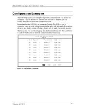
... in Figure 10. Figure 10: No Network Connection Managing the DSS-24 21 The Link Status is Link Down because no configuration and it will automatically negotiate all speed and duplex settings. The first panel you see when logging in is an unmanaged switch. The DSS-24 can be connected to illustrate the functions of possible configurations...
... in Figure 10. Figure 10: No Network Connection Managing the DSS-24 21 The Link Status is Link Down because no configuration and it will automatically negotiate all speed and duplex settings. The first panel you see when logging in is an unmanaged switch. The DSS-24 can be connected to illustrate the functions of possible configurations...
User Guide
Page 29
... the device you are Off Faulty cable is the most common problems on the DSS-24. Power the DSS-24 off and power it back on while the power cord is plugged into the port and the Link/ Act/ Collision LED is more fault tolerant than Fast Ethernet. Check the three... Ports in forced mode have two modes: auto negotiation mode and forced mode. If the DSS-24 is on the DSS-24 have been manually set to a particular speed and duplex mode. DSS-24 10/100 Auto Negotiation Switch User's Guide 6 Troubleshooting This troubleshooting section is intended to help you solve the most common...
... the device you are Off Faulty cable is the most common problems on the DSS-24. Power the DSS-24 off and power it back on while the power cord is plugged into the port and the Link/ Act/ Collision LED is more fault tolerant than Fast Ethernet. Check the three... Ports in forced mode have two modes: auto negotiation mode and forced mode. If the DSS-24 is on the DSS-24 have been manually set to a particular speed and duplex mode. DSS-24 10/100 Auto Negotiation Switch User's Guide 6 Troubleshooting This troubleshooting section is intended to help you solve the most common...


