
Product Manual
Page 3
... National Electrical Code et à la norme NFPA 75 ». Intended Readers The DMS-3130 Series Layer 3 Stackable Managed Switch Hardware Installation Guide contains detailed information about the hardware specifications of the socket-outlet is incorrectly replaced. Lithium battery Caution: There is a danger of battery. DMS-3130 Series Layer 3 Stackable Managed Switch Hardware Installation Guide The machine can only be used in a fixed location such as the Switch throughout this series will simply be referred to...
... National Electrical Code et à la norme NFPA 75 ». Intended Readers The DMS-3130 Series Layer 3 Stackable Managed Switch Hardware Installation Guide contains detailed information about the hardware specifications of the socket-outlet is incorrectly replaced. Lithium battery Caution: There is a danger of battery. DMS-3130 Series Layer 3 Stackable Managed Switch Hardware Installation Guide The machine can only be used in a fixed location such as the Switch throughout this series will simply be referred to...

Product Manual
Page 9
... Connecting to the Console Port ...35 Connecting to the RJ45 Console Port ...35 Connecting to a Server ...34 5. DMS-3130 Series Layer 3 Stackable Managed Switch Hardware Installation Guide Table of Contents Intended Readers ...3 Typographical Conventions ...3 Notes and Cautions ...4 Safety/Sécurité...4 Safety Instructions ...4 Safety Cautions ...4 Consignes de sécurité ...5 Précautions de sécurité ...6 General Precautions for the First Time...36 Creating a User Account...37 Configuring the IP Address...37 ix Hardware Components ...14 DMS-3130-30TS Switch...
... Connecting to the Console Port ...35 Connecting to the RJ45 Console Port ...35 Connecting to a Server ...34 5. DMS-3130 Series Layer 3 Stackable Managed Switch Hardware Installation Guide Table of Contents Intended Readers ...3 Typographical Conventions ...3 Notes and Cautions ...4 Safety/Sécurité...4 Safety Instructions ...4 Safety Cautions ...4 Consignes de sécurité ...5 Précautions de sécurité ...6 General Precautions for the First Time...36 Creating a User Account...37 Configuring the IP Address...37 ix Hardware Components ...14 DMS-3130-30TS Switch...
Product Manual
Page 10
DMS-3130 Series Layer 3 Stackable Managed Switch Hardware Installation Guide Connecting to RS-232) ...49 Redundant Power Supply (RPS) Cable ...50 CE RED Compliance Statement ...51 Additional Notice ...51 Technical Support ...52 x Technical Specifications ...43 General ...43 Physical and Environmental...43 Performance...44 LED Indicators ...44 Port Functions ...46 Appendix B - Cables and Connectors...48 Ethernet Cable ...48 Console Cable (RJ45 to the MGMT Port ...38 Connecting using SNMP ...38 Traps ...39 Management Information Base (MIB)...39 Web-based Switch Configuration...40...
DMS-3130 Series Layer 3 Stackable Managed Switch Hardware Installation Guide Connecting to RS-232) ...49 Redundant Power Supply (RPS) Cable ...50 CE RED Compliance Statement ...51 Additional Notice ...51 Technical Support ...52 x Technical Specifications ...43 General ...43 Physical and Environmental...43 Performance...44 LED Indicators ...44 Port Functions ...46 Appendix B - Cables and Connectors...48 Ethernet Cable ...48 Console Cable (RJ45 to the MGMT Port ...38 Connecting using SNMP ...38 Traps ...39 Management Information Base (MIB)...39 Web-based Switch Configuration...40...
Product Manual
Page 11
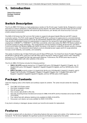
... 25G fiber connectivity, which continues to supply power to support multi-speed Gigabit Ethernet and SFP network connection options. This series of the Switch and carefully unpack its contents. Furthermore, the SFP28 ports may span great distances. The D-Link DMS-3130 Series includes the following items: • One DMS-3130 Series switch. • One Quick Installation Guide. • One AC power cord. • One console cable (RJ45 to RS-232). • One rack mounting kit (two brackets and screws for DMS-3130-30TS and...
... 25G fiber connectivity, which continues to supply power to support multi-speed Gigabit Ethernet and SFP network connection options. This series of the Switch and carefully unpack its contents. Furthermore, the SFP28 ports may span great distances. The D-Link DMS-3130 Series includes the following items: • One DMS-3130 Series switch. • One Quick Installation Guide. • One AC power cord. • One console cable (RJ45 to RS-232). • One rack mounting kit (two brackets and screws for DMS-3130-30TS and...

Product Manual
Page 12
DMS-3130 Series Layer 3 Stackable Managed Switch Hardware Installation Guide Features that can be found on this switch are: • Virtual Stacking. D-Link Single IP Management (SIM) • Physical Stacking, using the 10GBase-T and/or SFP28 (SFP+) ports with 80G or 200G (full-duplex) in Chain or Ring topology • Jumbo Frames (9K Bytes) • Spanning Tree Protocol (STP, RSTP, and MSTP) • Ethernet Ring Protection Switching (ERPS) • Link Aggregation • Mirroring (Port Mirroring, VLAN Mirroring, Flow-based (ACL) Mirroring, and RSPAN) • Loopback Detection...
DMS-3130 Series Layer 3 Stackable Managed Switch Hardware Installation Guide Features that can be found on this switch are: • Virtual Stacking. D-Link Single IP Management (SIM) • Physical Stacking, using the 10GBase-T and/or SFP28 (SFP+) ports with 80G or 200G (full-duplex) in Chain or Ring topology • Jumbo Frames (9K Bytes) • Spanning Tree Protocol (STP, RSTP, and MSTP) • Ethernet Ring Protection Switching (ERPS) • Link Aggregation • Mirroring (Port Mirroring, VLAN Mirroring, Flow-based (ACL) Mirroring, and RSPAN) • Loopback Detection...
Product Manual
Page 13
...) 13 DMS-3130 Series Layer 3 Stackable Managed Switch Hardware Installation Guide • Network Time Protocol (NTP) IPv4/IPv6 • Simple Network Time Protocol (SNTP) IPv4/IPv6 • Link Layer Discovery Protocol (LLDP), and LLDP-MED • User Account Privilege for Management Access • Command Line Interface (CLI) • Simple Network Management Protocol (SNMPv1/SNMPv2c/SNMPv3) IPv4/IPv6 • Remote Network Monitoring (RMONv1/RMONv2) • SNMP Trap • Web User Interface (Web UI) • D-Link Discover Protocol (DDP) • DHCP Server and Client, and DHCP Auto-
...) 13 DMS-3130 Series Layer 3 Stackable Managed Switch Hardware Installation Guide • Network Time Protocol (NTP) IPv4/IPv6 • Simple Network Time Protocol (SNTP) IPv4/IPv6 • Link Layer Discovery Protocol (LLDP), and LLDP-MED • User Account Privilege for Management Access • Command Line Interface (CLI) • Simple Network Management Protocol (SNMPv1/SNMPv2c/SNMPv3) IPv4/IPv6 • Remote Network Monitoring (RMONv1/RMONv2) • SNMP Trap • Web User Interface (Web UI) • D-Link Discover Protocol (DDP) • DHCP Server and Client, and DHCP Auto-

Product Manual
Page 14
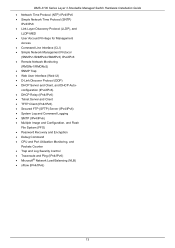
... wire-speed. DMS-3130 Series Layer 3 Stackable Managed Switch Hardware Installation Guide 2. This port uses a special console cable (included in this package) with this switch, refer to connect the Switch and the serial port (COM) of this switch are listed in the table below. These ports can be used as the main power source or as the secondary power source to the network. Technical Specifications. The Switch is equipped with 4 SFP28 (or optional SFP+) ports. The MGMT port can be used to configure the Switch without being connected...
... wire-speed. DMS-3130 Series Layer 3 Stackable Managed Switch Hardware Installation Guide 2. This port uses a special console cable (included in this package) with this switch, refer to connect the Switch and the serial port (COM) of this switch are listed in the table below. These ports can be used as the main power source or as the secondary power source to the network. Technical Specifications. The Switch is equipped with 4 SFP28 (or optional SFP+) ports. The MGMT port can be used to configure the Switch without being connected...

Product Manual
Page 15
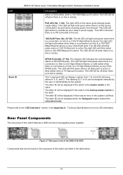
... when the Switch is no longer receiving power (i.e. powered off when there is no PSE connected to the port. DMS-3130 Series Layer 3 Stackable Managed Switch Hardware Installation Guide LED Console MGMT RPS Fan Error USB Link/Act/Speed LEDs Figure 2-2 LED indicators for Link and Activity. 2.5G RJ45 Ports (No.1~24): The LED at the right side has no LED notification. 10G RJ45 Ports (No. 25~26): The left LED will light solid green when there is a connection (or link) to a 2.5/5/10...
... when the Switch is no longer receiving power (i.e. powered off when there is no PSE connected to the port. DMS-3130 Series Layer 3 Stackable Managed Switch Hardware Installation Guide LED Console MGMT RPS Fan Error USB Link/Act/Speed LEDs Figure 2-2 LED indicators for Link and Activity. 2.5G RJ45 Ports (No.1~24): The LED at the right side has no LED notification. 10G RJ45 Ports (No. 25~26): The left LED will light solid green when there is a connection (or link) to a 2.5/5/10...

Product Manual
Page 16
.... When the internal power fails, this switch contain heat vents, fans, and rack-mounting screw holes. The stacking ID (1 to 9) can be found on the rear panel. The letter 'h' will be plugged into the notch and turn the key to secure the lock. LED Stack ID DMS-3130 Series Layer 3 Stackable Managed Switch Hardware Installation Guide Description green when a 25 Gbps port is active or blink amber when a 10 Gbps port is used to dissipate internal...
.... When the internal power fails, this switch contain heat vents, fans, and rack-mounting screw holes. The stacking ID (1 to 9) can be found on the rear panel. The letter 'h' will be plugged into the notch and turn the key to secure the lock. LED Stack ID DMS-3130 Series Layer 3 Stackable Managed Switch Hardware Installation Guide Description green when a 25 Gbps port is active or blink amber when a 10 Gbps port is used to dissipate internal...

Product Manual
Page 17
... view of the DMS-3130-30PS Ports that can be used to connect to the Command Line Interface (CLI) of this package) with a RJ45-to-Serial interface to connect the Switch and the serial port (COM) of LED indicators and ports. The Switch is an IP-based, Out-Of-Band (OOB) port for Telnet, web, or SNMP management that can be used to configure the Switch without being connected to IEEE802.3af, IEEE802.3at, and IEEE802.3bt. The RJ45 console port...
... view of the DMS-3130-30PS Ports that can be used to connect to the Command Line Interface (CLI) of this package) with a RJ45-to-Serial interface to connect the Switch and the serial port (COM) of LED indicators and ports. The Switch is an IP-based, Out-Of-Band (OOB) port for Telnet, web, or SNMP management that can be used to configure the Switch without being connected to IEEE802.3af, IEEE802.3at, and IEEE802.3bt. The RJ45 console port...

Product Manual
Page 18
... light solid green (1000 Mbps) or amber (10/100Mbps) after the Switch has been powered on any of the RJ45 ports. The LED will be off when the RPS is active. DMS-3130 Series Layer 3 Stackable Managed Switch Hardware Installation Guide For a complete list of SFP transceivers that are LED indicators: Power, Console, RPS, Fan Err, USB, Link/Act indicators for all the ports, and Stack ID. LED Indicators Located on any of the RJ45 ports. This LED will blink green...
... light solid green (1000 Mbps) or amber (10/100Mbps) after the Switch has been powered on any of the RJ45 ports. The LED will be off when the RPS is active. DMS-3130 Series Layer 3 Stackable Managed Switch Hardware Installation Guide For a complete list of SFP transceivers that are LED indicators: Power, Console, RPS, Fan Err, USB, Link/Act indicators for all the ports, and Stack ID. LED Indicators Located on any of the RJ45 ports. This LED will blink green...
Product Manual
Page 19
... no PD connected to the port. 10G RJ45 Ports (No. 25~26): The left LED will be found on any of the above ports indicate power supply status. The left LED will blink green when a 25 Gbps port is active or blink amber when a 10 Gbps port is active. The LED will be off when there is no link or activity. LED Stack ID DMS-3130 Series Layer 3 Stackable Managed Switch Hardware Installation Guide Description active or blink amber when...
... no PD connected to the port. 10G RJ45 Ports (No. 25~26): The left LED will be found on any of the above ports indicate power supply status. The left LED will blink green when a 25 Gbps port is active or blink amber when a 10 Gbps port is active. The LED will be off when there is no link or activity. LED Stack ID DMS-3130 Series Layer 3 Stackable Managed Switch Hardware Installation Guide Description active or blink amber when...
Product Manual
Page 29
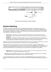
... and stack the Switches. DMS-3130 Series Layer 3 Stackable Managed Switch Hardware Installation Guide Figure 4-2 Connecting the Switch to another switch/hub Switch Stacking The DMS-3130 series supports stacking up to 100 Gbps will be used between two switches. Physical stacking number in one console connection on the Switch can be transferred in a Duplex Chain formation using Telnet, the Web UI, and SNMP. Note: Modules with SFP28 connectors where the 2-port or 4-port stacking configuration is used for administrators to upgrade their networks using the SFP28 ports to...
... and stack the Switches. DMS-3130 Series Layer 3 Stackable Managed Switch Hardware Installation Guide Figure 4-2 Connecting the Switch to another switch/hub Switch Stacking The DMS-3130 series supports stacking up to 100 Gbps will be used between two switches. Physical stacking number in one console connection on the Switch can be transferred in a Duplex Chain formation using Telnet, the Web UI, and SNMP. Note: Modules with SFP28 connectors where the 2-port or 4-port stacking configuration is used for administrators to upgrade their networks using the SFP28 ports to...
Product Manual
Page 35
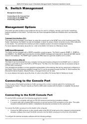
... statistics and counters. This cable should be accessed from any of the LAN ports on the front of the RJ45 or SFP28 ports. The SNMP agent updates the MIB objects to the DMS-3130 Series Web UI Reference Guide. The SNMP agent decodes the incoming SNMP messages and responds to requests with the Switch. To configure the terminal emulation software with a SNMP-compatible console program. DMS-3130 Series Layer 3 Stackable Managed Switch Hardware Installation Guide 5. Currently there are three...
... statistics and counters. This cable should be accessed from any of the LAN ports on the front of the RJ45 or SFP28 ports. The SNMP agent updates the MIB objects to the DMS-3130 Series Web UI Reference Guide. The SNMP agent decodes the incoming SNMP messages and responds to requests with the Switch. To configure the terminal emulation software with a SNMP-compatible console program. DMS-3130 Series Layer 3 Stackable Managed Switch Hardware Installation Guide 5. Currently there are three...

Product Manual
Page 36
DMS-3130 Series Layer 3 Stackable Managed Switch Hardware Installation Guide • Select the appropriate serial port (COM1 or COM2). • Set the data rate to 115200 baud. • Set the data format to 8 data bits, 1 stop bit, and no Username and Password configured in the terminal. The simplest way, at this stage, to reboot the Switch is to unplug and re-insert the power cable from accessing the Switch or changing its configuration. Connecting to the management interface. 36 DMS-3130-30TS Gigabit Ethernet Switch Switch> Command Line Interface Firmware: Build 1.00.B009 ...
DMS-3130 Series Layer 3 Stackable Managed Switch Hardware Installation Guide • Select the appropriate serial port (COM1 or COM2). • Set the data rate to 115200 baud. • Set the data format to 8 data bits, 1 stop bit, and no Username and Password configured in the terminal. The simplest way, at this stage, to reboot the Switch is to unplug and re-insert the power cable from accessing the Switch or changing its configuration. Connecting to the management interface. 36 DMS-3130-30TS Gigabit Ethernet Switch Switch> Command Line Interface Firmware: Build 1.00.B009 ...
Product Manual
Page 37
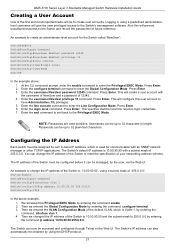
... Switch>enable Switch#configure terminal Switch(config)#interface vlan 1 Switch(config-if)#ip address 10.50.50.50 255.0.0.0 Switch(config-if)# In the above : 1. Press Enter. At the CLI command prompt, enter the enable command to create user accounts. An example to change the IP address of the Switch to create an administrator-level account for communication with an SNMP network manager or other TCP/IP applications. Enter the username NewUser password 12345 command. DMS-3130 Series Layer 3 Stackable Managed Switch Hardware Installation Guide Creating a User...
... Switch>enable Switch#configure terminal Switch(config)#interface vlan 1 Switch(config-if)#ip address 10.50.50.50 255.0.0.0 Switch(config-if)# In the above : 1. Press Enter. At the CLI command prompt, enter the enable command to create user accounts. An example to change the IP address of the Switch to create an administrator-level account for communication with an SNMP network manager or other TCP/IP applications. Enter the username NewUser password 12345 command. DMS-3130 Series Layer 3 Stackable Managed Switch Hardware Installation Guide Creating a User...
Product Manual
Page 38
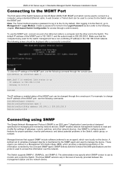
... used to connect to monitor and control the Switch. Make sure that support SNMP include software (referred to the Switch. The administrator may specify which can be used to the CLI by the on the device. Create a password for the switch management has a non-conflicting IP address in the level of the information controlled by default. To use the following commands: Switch#configure terminal Switch(config)#interface mgmt 0 Switch(config-if)#ip address 192.168.1.1 255.255.255.0 Switch(config-if)# Connecting using a standard Ethernet cable. SNMP...
... used to connect to monitor and control the Switch. Make sure that support SNMP include software (referred to the Switch. The administrator may specify which can be used to the CLI by the on the device. Create a password for the switch management has a non-conflicting IP address in the level of the information controlled by default. To use the following commands: Switch#configure terminal Switch(config)#interface mgmt 0 Switch(config-if)#ip address 192.168.1.1 255.255.255.0 Switch(config-if)# Connecting using a standard Ethernet cable. SNMP...
Product Manual
Page 40
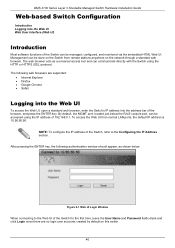
DMS-3130 Series Layer 3 Stackable Managed Switch Hardware Installation Guide Web-based Switch Configuration Introduction Logging into the address bar of 192.168.0.1. Management can be accessed using the HTTP or HTTPS (SSL) protocol. To access the Web UI from remote stations anywhere on this switch. 40 After pressing the ENTER key, the following web browsers are no login user accounts created by default on the network through a standard web browser. NOTE: To configure the IP address of the Switch can be done...
DMS-3130 Series Layer 3 Stackable Managed Switch Hardware Installation Guide Web-based Switch Configuration Introduction Logging into the address bar of 192.168.0.1. Management can be accessed using the HTTP or HTTPS (SSL) protocol. To access the Web UI from remote stations anywhere on this switch. 40 After pressing the ENTER key, the following web browsers are no login user accounts created by default on the network through a standard web browser. NOTE: To configure the IP address of the Switch can be done...
Product Manual
Page 43
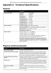
... the Switch, to be able to connect to maintain the time setting when the device power is intended to secure the lock. Available on DMS-3130-30PS only. The lock-and-cable apparatus should be supplied by UL Listed Power source. Technical Specifications General Feature Data Transfer Rates Physical Stacking Network Cables Description Standards Full-duplex Ethernet 20 Mbps Fast Ethernet 200 Mbps Gigabit Ethernet 2 Gbps 2.5 Gigabit Ethernet 5 Gbps 5 Gigabit Ethernet 10 Gbps 10 Gigabit Ethernet 20 Gbps 25 Gigabit Ethernet...
... the Switch, to be able to connect to maintain the time setting when the device power is intended to secure the lock. Available on DMS-3130-30PS only. The lock-and-cable apparatus should be supplied by UL Listed Power source. Technical Specifications General Feature Data Transfer Rates Physical Stacking Network Cables Description Standards Full-duplex Ethernet 20 Mbps Fast Ethernet 200 Mbps Gigabit Ethernet 2 Gbps 2.5 Gigabit Ethernet 5 Gbps 5 Gigabit Ethernet 10 Gbps 10 Gigabit Ethernet 20 Gbps 25 Gigabit Ethernet...

Product Manual
Page 45
DMS-3130 Series Layer 3 Stackable Managed Switch Hardware Installation Guide Location LED Console Fan Err RPS USB Stacking ID (7-segment LED) LED Per 10/100/1000 Mbps Port Link/Act/Speed LED Per 2.5 Gbps Port Link/Act/Speed PSE (for DMS3130-30PS only) LED Per 5 Gbps Port (for DMS-313030PS only) Link/Act/Speed Color Off Green Off Red Off Green Green Off Green Green Amber Off Green Amber Off Green Amber Off Green Status Light off Light on (Solid) Light off Light on (Solid) Light off Light on (Solid) Light off Light on (Solid) Light blinking Light off Light on (1-9) Light on (H) Light...
DMS-3130 Series Layer 3 Stackable Managed Switch Hardware Installation Guide Location LED Console Fan Err RPS USB Stacking ID (7-segment LED) LED Per 10/100/1000 Mbps Port Link/Act/Speed LED Per 2.5 Gbps Port Link/Act/Speed PSE (for DMS3130-30PS only) LED Per 5 Gbps Port (for DMS-313030PS only) Link/Act/Speed Color Off Green Off Red Off Green Green Off Green Green Amber Off Green Amber Off Green Amber Off Green Status Light off Light on (Solid) Light off Light on (Solid) Light off Light on (Solid) Light off Light on (Solid) Light blinking Light off Light on (1-9) Light on (H) Light...


