
Product Manual
Page 1
DMC-700SC 1000BASE-TX to 1000BASE-SX Media Converter User's Guide RECYCLABLE 19071001TSC6003 Rev.1.00
DMC-700SC 1000BASE-TX to 1000BASE-SX Media Converter User's Guide RECYCLABLE 19071001TSC6003 Rev.1.00
Product Manual
Page 2
TABLE OF CONTENTS TABLE OF CONTENTS .......... 2 INTRODUCTION 3 ABOUT THE MEDIA CONVERTER 3 PRODUCT FEATURES ...... 3 INSTALLATION 3 SELECTING A SITE FOR THE EQUIPMENT 3 CONNECTING TO POWER 4 LED INDICATOR 4 LINK PASS THROUGH FUNCTION 5 SWITCH 6 SPECIFICATIONS 8 WARRANTY 9 REGISTRATION 15 2
TABLE OF CONTENTS TABLE OF CONTENTS .......... 2 INTRODUCTION 3 ABOUT THE MEDIA CONVERTER 3 PRODUCT FEATURES ...... 3 INSTALLATION 3 SELECTING A SITE FOR THE EQUIPMENT 3 CONNECTING TO POWER 4 LED INDICATOR 4 LINK PASS THROUGH FUNCTION 5 SWITCH 6 SPECIFICATIONS 8 WARRANTY 9 REGISTRATION 15 2
Product Manual
Page 3
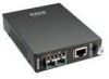
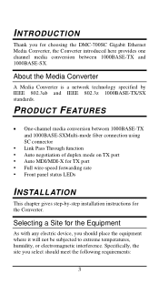
... 1000BASE-SX. Specifically, the site you for the Converter. About the Media Converter A Media Converter is a network technology specified by -step installation instructions for choosing the DMC-700SC Gigabit Ethernet Media Converter, the Converter introduced here provides one channel media conversion between 1000BASE-TX and 1000BASE-SXMulti-mode fiber connection using SC connector y Link Pass Through function y Auto negotiation of duplex mode...
... 1000BASE-SX. Specifically, the site you for the Converter. About the Media Converter A Media Converter is a network technology specified by -step installation instructions for choosing the DMC-700SC Gigabit Ethernet Media Converter, the Converter introduced here provides one channel media conversion between 1000BASE-TX and 1000BASE-SXMulti-mode fiber connection using SC connector y Link Pass Through function y Auto negotiation of duplex mode...
Product Manual
Page 4
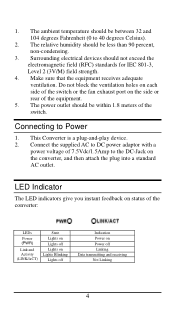
... electrical devices should be within 1.8 meters of the equipment. 5. Connecting to DC power adaptor with a power voltage of the converter: LEDs Power (PWR) Link and Activity (LINK/ACT) State Lights on Lights off Lights on Lights Blinking Lights off Indication Power on the... converter, and then attach the plug into a standard AC outlet. This Converter is a plug-and-play device. 2. 1. The relative humidity should be less than 90 percent, non...
... electrical devices should be within 1.8 meters of the equipment. 5. Connecting to DC power adaptor with a power voltage of the converter: LEDs Power (PWR) Link and Activity (LINK/ACT) State Lights on Lights off Lights on Lights Blinking Lights off Indication Power on the... converter, and then attach the plug into a standard AC outlet. This Converter is a plug-and-play device. 2. 1. The relative humidity should be less than 90 percent, non...
Product Manual
Page 5
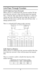
... on this function of the media converter. The table below shows how the LLCF function works: Media Converter A Fiber TX RX LINK 2 Copper Media Converter B LINK 3 Fiber Copper TX R X Cable 1 Cable 2 Cable 5 Cable 4 Cable 3 R X TX LINK 1 Gigabit Switch Link Status Disconnect Cable 1 Cable 2 Cable 3 Cable 4 Cable 5 Link 1 Off Off On Off Off LINK 4 RX TX Gigabit Switch Link 2 On Off On Off Off...
... on this function of the media converter. The table below shows how the LLCF function works: Media Converter A Fiber TX RX LINK 2 Copper Media Converter B LINK 3 Fiber Copper TX R X Cable 1 Cable 2 Cable 5 Cable 4 Cable 3 R X TX LINK 1 Gigabit Switch Link Status Disconnect Cable 1 Cable 2 Cable 3 Cable 4 Cable 5 Link 1 Off Off On Off Off LINK 4 RX TX Gigabit Switch Link 2 On Off On Off Off...
Product Manual
Page 6
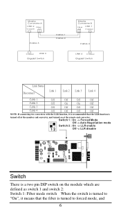
Media Converter A LINK 2 Fiber Copper TX RX Cab le 3 Copper LINK 3 Gigabit Switch Cab le 1 Cab le 2 Media Converter B Fiber TX R X LINK 1 Copper Cab le 4 LINK 4 Copper Gigabit Switch Link Status Disconnect Link 1 Link 2 Link 3 Link 4 Cable 1 Off Off Off Off Cable 2 Off On On Off Cable 3 Off Off Off Off Cable 4 Off Off Off Off NOTE: If connecting two converters with the LLR ... on the module which are defined as switch 1 and switch 2: Switch 1: Fiber mode switch When the switch is turned off at the monitor end converter, and turned on at the remote end...
Media Converter A LINK 2 Fiber Copper TX RX Cab le 3 Copper LINK 3 Gigabit Switch Cab le 1 Cab le 2 Media Converter B Fiber TX R X LINK 1 Copper Cab le 4 LINK 4 Copper Gigabit Switch Link Status Disconnect Link 1 Link 2 Link 3 Link 4 Cable 1 Off Off Off Off Cable 2 Off On On Off Cable 3 Off Off Off Off Cable 4 Off Off Off Off NOTE: If connecting two converters with the LLR ... on the module which are defined as switch 1 and switch 2: Switch 1: Fiber mode switch When the switch is turned off at the monitor end converter, and turned on at the remote end...

Product Manual
Page 7
"Off" for disabled. Note: When connecting two converters, only enable the LLR function on one device. 7 Switch 2: LLR When the switch is turned to forced mode. Note: Be sure the opposite end is enabled and "Off" for auto-negotiation mode. When connecting two converters both MUST be set to "On", it means that LLR is using the same setting (forced or Auto-negotiation).
"Off" for disabled. Note: When connecting two converters, only enable the LLR function on one device. 7 Switch 2: LLR When the switch is turned to forced mode. Note: Be sure the opposite end is enabled and "Off" for auto-negotiation mode. When connecting two converters both MUST be set to "On", it means that LLR is using the same setting (forced or Auto-negotiation).
