Product Manual
Page 1
DKVM-2/4 2/4-Port Keyboard, Video, and Mouse Switch Manual Rev. 1.2
DKVM-2/4 2/4-Port Keyboard, Video, and Mouse Switch Manual Rev. 1.2

Product Manual
Page 2
Contents Introduction 1 Hardware Installation 2 Front Panel Layout 2 Rear Panel Layout 2 Using the DKVM-2/4 6 "Select" button 6 Keyboard "Hot Key commands 7 Optional cable 7 Troubleshooting 8 Keyboard ...8 Mouse ...8 Video ...10 Product Features 1 Specifications 11 FCC Certifications 12 D-Link Offices 13 II
Contents Introduction 1 Hardware Installation 2 Front Panel Layout 2 Rear Panel Layout 2 Using the DKVM-2/4 6 "Select" button 6 Keyboard "Hot Key commands 7 Optional cable 7 Troubleshooting 8 Keyboard ...8 Mouse ...8 Video ...10 Product Features 1 Specifications 11 FCC Certifications 12 D-Link Offices 13 II
Product Manual
Page 3
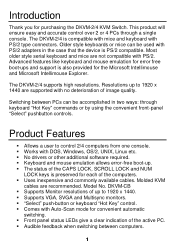
Model No. DKVM-CB § Supports Monitor resolutions of up to control 2/4 computers from one console. § Works with DOS, Windows, OS/2, UNIX, Linux etc. § No drivers or other additional software required. § Keyboard and mouse emulation allows error-free boot-up to 1920 x 1440 are recommended. Introduction Thank you for convenient automatic switching. § Front panel status LEDs give a clear indication of the active PC. § Audible feedback...
Model No. DKVM-CB § Supports Monitor resolutions of up to control 2/4 computers from one console. § Works with DOS, Windows, OS/2, UNIX, Linux etc. § No drivers or other additional software required. § Keyboard and mouse emulation allows error-free boot-up to 1920 x 1440 are recommended. Introduction Thank you for convenient automatic switching. § Front panel status LEDs give a clear indication of the active PC. § Audible feedback...
Product Manual
Page 4
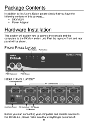
FRONT PANEL LAYOUT REAR PANEL LAYOUT Before you start connecting your computers and console devices to the DKVM-2/4, please make sure that you have the following contents of front and rear panel will explain how to connect the console and the computers to the DKVM-4 switch unit. First the layout of this package... § DKVM-2/4 § Power Adapter Hardware Installation This section will be shown. Package Contents In addition to this User's Guide, please check that everything is powered off. 2
FRONT PANEL LAYOUT REAR PANEL LAYOUT Before you start connecting your computers and console devices to the DKVM-2/4, please make sure that you have the following contents of front and rear panel will explain how to connect the console and the computers to the DKVM-4 switch unit. First the layout of this package... § DKVM-2/4 § Power Adapter Hardware Installation This section will be shown. Package Contents In addition to this User's Guide, please check that everything is powered off. 2

Product Manual
Page 5
... and then install the Windows native mouse driver. Step 2. Note: Please make sure the mouse you are planning to use is a 2 Button or 3 Button mouse, and that it easy to place on the rear panel. Step 3. Connect it to the two 6-pin Mini DIN connectors labeled =CONSOLE= as shown, otherwise, keyboard and/or mouse errors may occur. If your mouse driver is not Microsoft mouse driver compatible, please...
... and then install the Windows native mouse driver. Step 2. Note: Please make sure the mouse you are planning to use is a 2 Button or 3 Button mouse, and that it easy to place on the rear panel. Step 3. Connect it to the two 6-pin Mini DIN connectors labeled =CONSOLE= as shown, otherwise, keyboard and/or mouse errors may occur. If your mouse driver is not Microsoft mouse driver compatible, please...

Product Manual
Page 6
... made with the Male side to both the PC and to the DKVM-2/4 unit. To finish the hardware installation, connect the PS/2 keyboard cables from your computers to 4 Connect a keyboard cable (6-pin Mini DIN Male / Male) to the PC and to the DKVM-2/4 unit. Step 5. Now connect the PS/2 mouse cables from your computers to the connector labeled VGA on the rear panel...
... made with the Male side to both the PC and to the DKVM-2/4 unit. To finish the hardware installation, connect the PS/2 keyboard cables from your computers to 4 Connect a keyboard cable (6-pin Mini DIN Male / Male) to the PC and to the DKVM-2/4 unit. Step 5. Now connect the PS/2 mouse cables from your computers to the connector labeled VGA on the rear panel...
Product Manual
Page 7
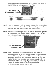
... has booted up , and you find errors, re-check all cables. Switch on the monitor. In particular, keyboard and mouse cables should be shown on your monitor. If this for Port 1 light up . Repeat this is connected to the DKVM-2/4 unit and plug it into a power outlet. Step 9. If you will be checked because they are easily switched and they use the "Select" button to the troubleshooting section of this manual. 5
... has booted up , and you find errors, re-check all cables. Switch on the monitor. In particular, keyboard and mouse cables should be shown on your monitor. If this for Port 1 light up . Repeat this is connected to the DKVM-2/4 unit and plug it into a power outlet. Step 9. If you will be checked because they are easily switched and they use the "Select" button to the troubleshooting section of this manual. 5

Product Manual
Page 8
... the mouse operates properly. "SELECT" BUTTON Pressing the Select button cycles through computers 1 ~ 2/4 6 Use either the "Select" b utton on the KVM at this moment, it will communicate with the keyboard and mouse. Do not press the push button of the keyboard "Hot key" commands. This is normal and is the active system. Note: Please do not switch the PC port (i.e. Normally, during boot-up...
... the mouse operates properly. "SELECT" BUTTON Pressing the Select button cycles through computers 1 ~ 2/4 6 Use either the "Select" b utton on the KVM at this moment, it will communicate with the keyboard and mouse. Do not press the push button of the keyboard "Hot key" commands. This is normal and is the active system. Note: Please do not switch the PC port (i.e. Normally, during boot-up...
Product Manual
Page 9
....dlinkshop.com for DKVM-2/4 KVM switch. SCROLL LOCK SCROLL LOCK ? Erratic input will be shown on the monitor in -one has been shown. To exit Auto-Scan mode, press the SPACE BAR. You will result if a mouse move or keyboard key press is needed to prevent errors. SCROLL LOCK SCROLL LOCK S COMMAND Switch to First PC Switch to Second PC Switch to Third PC Switch to...
....dlinkshop.com for DKVM-2/4 KVM switch. SCROLL LOCK SCROLL LOCK ? Erratic input will be shown on the monitor in -one has been shown. To exit Auto-Scan mode, press the SPACE BAR. You will result if a mouse move or keyboard key press is needed to prevent errors. SCROLL LOCK SCROLL LOCK S COMMAND Switch to First PC Switch to Second PC Switch to Third PC Switch to...
Product Manual
Page 10
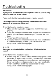
Troubleshooting KEYBOARD My keyboard is not detected, or a keyboard error is given during boot up . Please verify that the keyboard cables are inserted properly. One of connector and are therefore easily confused. § Read your motherboard documentation and make sure that the PS/2 mouse IRQ is enabled. (This can be the case: § Please verify that the PS/2 keyboard IRQ is enabled. (This can...
Troubleshooting KEYBOARD My keyboard is not detected, or a keyboard error is given during boot up . Please verify that the keyboard cables are inserted properly. One of connector and are therefore easily confused. § Read your motherboard documentation and make sure that the PS/2 mouse IRQ is enabled. (This can be the case: § Please verify that the PS/2 keyboard IRQ is enabled. (This can...

Product Manual
Page 11
... mouse or press any mouse buttons while switching from the DKVM-2/4 unit for a standard PS/2 or fully Microsoft compatible PS/2 mouse. The computers boot properly but it must be set to PS/2 mode and the correct serial mouse to PS/2 adapter must be 9V 600mA. Its rating must be the case: § Verify that it from one mouse driver installed. A combination mouse will not work , but I switch between computers, mouse...
... mouse or press any mouse buttons while switching from the DKVM-2/4 unit for a standard PS/2 or fully Microsoft compatible PS/2 mouse. The computers boot properly but it must be set to PS/2 mode and the correct serial mouse to PS/2 adapter must be 9V 600mA. Its rating must be the case: § Verify that it from one mouse driver installed. A combination mouse will not work , but I switch between computers, mouse...

Product Manual
Page 12
... the systems. VIDEO The image on my monitor is not clear. Try a lower refresh rate, or try lowering the resolution. § Your video cable may be powered-up. Please use video cables that are inserted properly. § It may be connected. But before powering the DKVM-2/4 unit up, the mouse and keyboard must be too long. What can be 9V 600mA. 10 Its rating must be...
... the systems. VIDEO The image on my monitor is not clear. Try a lower refresh rate, or try lowering the resolution. § Your video cable may be powered-up. Please use video cables that are inserted properly. § It may be connected. But before powering the DKVM-2/4 unit up, the mouse and keyboard must be too long. What can be 9V 600mA. 10 Its rating must be...
Product Manual
Page 13
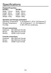
Specifications Physical Properties: DKVM-2 DKVM-4 Width: 119mm Width: 185mm Height: 46mm Height: 46mm Depth: 105mm Depth: 105mm Weight: 478g Weight: 684g Operation and Storage parameters: Operating Temperature: 0~40 Degrees C (32 to 104 Degrees F) Storage Temperature: -20~60 Degrees C (-4~140 Degrees F) Humidity: 0~80% RH non condensing PC port connections Keyboard: Mini DIN 6 pin Female Mouse: Mini DIN 6 pin Female Monitor: HDDB 15 pin Female Console connections Keyboard: Mini DIN 6 pin Female Mouse: Mini DIN 6 pin Female Monitor: HDDB 15 pin Female 11
Specifications Physical Properties: DKVM-2 DKVM-4 Width: 119mm Width: 185mm Height: 46mm Height: 46mm Depth: 105mm Depth: 105mm Weight: 478g Weight: 684g Operation and Storage parameters: Operating Temperature: 0~40 Degrees C (32 to 104 Degrees F) Storage Temperature: -20~60 Degrees C (-4~140 Degrees F) Humidity: 0~80% RH non condensing PC port connections Keyboard: Mini DIN 6 pin Female Mouse: Mini DIN 6 pin Female Monitor: HDDB 15 pin Female Console connections Keyboard: Mini DIN 6 pin Female Mouse: Mini DIN 6 pin Female Monitor: HDDB 15 pin Female 11

Product Manual
Page 14
... accordance with the instructions, may cause radio 12 These limits are cautioned that to which the receiver is subject to the following two conditions: (1) This device may not cause harmful interference, and (2) This device must be used in a residential installation. If this product may cause harmful interference to radio communications. Shielded interface cables must accept...
... accordance with the instructions, may cause radio 12 These limits are cautioned that to which the receiver is subject to the following two conditions: (1) This device may not cause harmful interference, and (2) This device must be used in a residential installation. If this product may cause harmful interference to radio communications. Shielded interface cables must accept...
Product Manual
Page 16
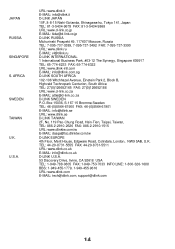
..., Taiwan, TEL: 886-2-2910-2626 FAX: 886-2-2910-1515 URL: www.dlinktw.com.tw E- MAIL: [email protected] D-LINK U.S.A. 53 Discovery Drive, Irvine, CA 92618 USA TEL: 1-949-788-0805 FAX: 1-949-753-7033 INFO LINE: 1-800-326-1688 BBS: 1-949-455-1779, 1-949-455-9616 URL: ...com.tw D-LINK EUROPE 4th Floor, Merit House, Edgware Road, Colindale, London, NW9 5AB, U.K. URL: www.dlink.it D-LINK JAPAN 10F, 8-8-15 Nishi-Gotanda, Shinagawa-ku, Tokyo 141, Japan TEL: 81-3-5434-9678 FAX: 81-3-5434-9868 URL: www.d-link.co.jp E- MAIL: attie@d-link.co.za D-LINK SWEDEN P.O. MAIL: tech@dlink.com, support@dlink.com...
..., Taiwan, TEL: 886-2-2910-2626 FAX: 886-2-2910-1515 URL: www.dlinktw.com.tw E- MAIL: [email protected] D-LINK U.S.A. 53 Discovery Drive, Irvine, CA 92618 USA TEL: 1-949-788-0805 FAX: 1-949-753-7033 INFO LINE: 1-800-326-1688 BBS: 1-949-455-1779, 1-949-455-9616 URL: ...com.tw D-LINK EUROPE 4th Floor, Merit House, Edgware Road, Colindale, London, NW9 5AB, U.K. URL: www.dlink.it D-LINK JAPAN 10F, 8-8-15 Nishi-Gotanda, Shinagawa-ku, Tokyo 141, Japan TEL: 81-3-5434-9678 FAX: 81-3-5434-9868 URL: www.d-link.co.jp E- MAIL: attie@d-link.co.za D-LINK SWEDEN P.O. MAIL: tech@dlink.com, support@dlink.com...

Product Manual
Page 17
... software updates and user documentation on this product. Tech Support for the duration of the unit · Model number or product name · Software type and version number D-Link provides free technical support for customers within the United States and within Canada: D-Link Technical Support over the Telephone: (800) 361-5265 Monday to Friday 7:30am to 12:00am EST D-Link Technical Support over the Internet: http://support.dlink.com email:support...
... software updates and user documentation on this product. Tech Support for the duration of the unit · Model number or product name · Software type and version number D-Link provides free technical support for customers within the United States and within Canada: D-Link Technical Support over the Telephone: (800) 361-5265 Monday to Friday 7:30am to 12:00am EST D-Link Technical Support over the Internet: http://support.dlink.com email:support...
Product Manual
Page 18
... D- Repaired or replacement hardware will be new or have an identical make, model or part. Except as set forth herein, D-Link Systems, Inc. ("D-Link") provides this Limited Warranty will be , at no charge to the original owner or to the Software. Military Installations, or addresses with software that substantially conforms to D-Link's functional specifications for the defective Hardware will substantially conform to D-Link's then current functional specifications...
... D- Repaired or replacement hardware will be new or have an identical make, model or part. Except as set forth herein, D-Link Systems, Inc. ("D-Link") provides this Limited Warranty will be , at no charge to the original owner or to the Software. Military Installations, or addresses with software that substantially conforms to D-Link's functional specifications for the defective Hardware will substantially conform to D-Link's then current functional specifications...
Product Manual
Page 19
...from D-Link Technical Support at https://rma.dlink.com/. • After an RMA number is issued, the defective product must be packaged securely in the original or other sales in which a refund is determined by D-Link or become the property of D-Link. ...Link. Replacement Software will be warranted for Hardware and Software portions of the product and will not be defective or non-conforming. If a material non-conformance is incapable of the product (such as described herein, notwithstanding anything stated herein to D-Link. provided that is given automatically terminates...
...from D-Link Technical Support at https://rma.dlink.com/. • After an RMA number is issued, the defective product must be packaged securely in the original or other sales in which a refund is determined by D-Link or become the property of D-Link. ...Link. Replacement Software will be warranted for Hardware and Software portions of the product and will not be defective or non-conforming. If a material non-conformance is incapable of the product (such as described herein, notwithstanding anything stated herein to D-Link. provided that is given automatically terminates...
Product Manual
Page 20
... FOR A PARTICULAR PURPOSE AND NONINFRINGEMENT. This Limited Warranty provides specific legal rights and you use only an Authorized D-Link Service Office. Trademarks: D-Link is not contemplated in the documentation for the product, or if the model or serial number has been altered, tampered with, defaced or removed; Initial installation, installation and removal of D-Link Systems, Inc. Some states do not allow exclusion or limitation...
... FOR A PARTICULAR PURPOSE AND NONINFRINGEMENT. This Limited Warranty provides specific legal rights and you use only an Authorized D-Link Service Office. Trademarks: D-Link is not contemplated in the documentation for the product, or if the model or serial number has been altered, tampered with, defaced or removed; Initial installation, installation and removal of D-Link Systems, Inc. Some states do not allow exclusion or limitation...
Product Manual
Page 21
...instructions, may cause harmful interference to which the receiver is encouraged to try to correct the interference by one or more of the FCC Rules. This equipment generates, uses..., and can be required to products purchased outside the United States, please contact the corresponding local D-Link office. However, there is a Class B product. These limits are designed to part...a particular installation. For detailed warranty information applicable to take adequate measures. If this product may be determined by turning the equipment off and on, the user is connected. •...
...instructions, may cause harmful interference to which the receiver is encouraged to try to correct the interference by one or more of the FCC Rules. This equipment generates, uses..., and can be required to products purchased outside the United States, please contact the corresponding local D-Link office. However, there is a Class B product. These limits are designed to part...a particular installation. For detailed warranty information applicable to take adequate measures. If this product may be determined by turning the equipment off and on, the user is connected. •...


