
Hardware Installation Guide
Page 4
...your system from the electrical outlet and replace the part or contact your device. DGS-3630 Series Layer 3 Stackable Managed Switch Hardware Installation Guide Intended Readers The DGS-3630 Series Layer 3 Stackable Managed Switch Hardware Installation Guide contains detailed information about the ... personal injury, or death. iv Typographical Conventions Convention Boldface Font Initial capital letter Blue Courier Font Description This convention is used to configure and manage a switch in this series. It also indicates a button, toolbar icon, menu, menu item, system message, or ...
...your system from the electrical outlet and replace the part or contact your device. DGS-3630 Series Layer 3 Stackable Managed Switch Hardware Installation Guide Intended Readers The DGS-3630 Series Layer 3 Stackable Managed Switch Hardware Installation Guide contains detailed information about the ... personal injury, or death. iv Typographical Conventions Convention Boldface Font Initial capital letter Blue Courier Font Description This convention is used to configure and manage a switch in this series. It also indicates a button, toolbar icon, menu, menu item, system message, or ...
Hardware Installation Guide
Page 8
...using SNMP ...42 Traps...42 Management Information Base (MIB)...43 6. DGS-3630 Series Layer 3 Stackable Managed Switch Hardware Installation Guide Connecting to the Switch for the First Time...40 Creating a User Account...40 Configuring the IP Address...41 Connecting to Mini-USB) ...54 Redundant ...Technical Specifications ...47 General ...47 Physical and Environmental...47 Performance...48 LED Indicators ...49 Port Functions ...50 Appendix B - Web-based Switch Configuration ...44 Introduction ...44 Logging into the Web UI ...44 Web User Interface (Web UI)...45 Areas of the Web UI ...45 Web ...
...using SNMP ...42 Traps...42 Management Information Base (MIB)...43 6. DGS-3630 Series Layer 3 Stackable Managed Switch Hardware Installation Guide Connecting to the Switch for the First Time...40 Creating a User Account...40 Configuring the IP Address...41 Connecting to Mini-USB) ...54 Redundant ...Technical Specifications ...47 General ...47 Physical and Environmental...47 Performance...48 LED Indicators ...49 Port Functions ...50 Appendix B - Web-based Switch Configuration ...44 Introduction ...44 Logging into the Web UI ...44 Web User Interface (Web UI)...45 Areas of the Web UI ...45 Web ...

Hardware Installation Guide
Page 11
... System Log and Command Logging SMTP (IPv4/IPv6) DNS Resolver and Relay (IPv4/IPv6) Multiple Image and Configuration, and Flash File System (FFS) Password Recovery and Encryption Debug Command CPU and Port Utilization Monitoring, and ...RMONv1/RMONv2) SNMP Trap Web User Interface (Web UI) D-Link Discover Protocol (DDP), and D-Link Network Assistant (DNA) DHCP Server and Client, and DHCP Auto- DGS-3630 Series Layer 3 Stackable Managed Switch Hardware Installation Guide Access Control List (ACL): ...
... System Log and Command Logging SMTP (IPv4/IPv6) DNS Resolver and Relay (IPv4/IPv6) Multiple Image and Configuration, and Flash File System (FFS) Password Recovery and Encryption Debug Command CPU and Port Utilization Monitoring, and ...RMONv1/RMONv2) SNMP Trap Web User Interface (Web UI) D-Link Discover Protocol (DDP), and D-Link Network Assistant (DNA) DHCP Server and Client, and DHCP Auto- DGS-3630 Series Layer 3 Stackable Managed Switch Hardware Installation Guide Access Control List (ACL): ...

Hardware Installation Guide
Page 13
...used to connect to the CLI of the Switch for portable firmware images and configuration files that can be copied to the serial port (COM) of the DGS-3630-28TC Ports that are shorted among the pair. Hardware Components This chapter describes the front...The RJ45 ports can operate at 10 Mbps, 100 Mbps, and 1 Gbps wire-speeds. DGS-3630-28TC Switch DGS-3630-28SC Switch DGS-3630-52TC Switch DGS-3630-28TC Switch Front Panel Components The front panel of DGS-3630-28TC features a variety of SFP/SFP+ transceivers. Port Description Alarm USB MGMT Console (RJ45) ...
...used to connect to the CLI of the Switch for portable firmware images and configuration files that can be copied to the serial port (COM) of the DGS-3630-28TC Ports that are shorted among the pair. Hardware Components This chapter describes the front...The RJ45 ports can operate at 10 Mbps, 100 Mbps, and 1 Gbps wire-speeds. DGS-3630-28TC Switch DGS-3630-28SC Switch DGS-3630-52TC Switch DGS-3630-28TC Switch Front Panel Components The front panel of DGS-3630-28TC features a variety of SFP/SFP+ transceivers. Port Description Alarm USB MGMT Console (RJ45) ...

Hardware Installation Guide
Page 14
.... powered off when there is no longer receiving power (i.e. This LED will be off when there is a connection (or link) to 9) can display numbers from within the Switch's configuration. This LED will blink green when a 1000 Mbps port is active or blink amber when a 100 Mbps port is plugged...is active. This 7-segment LED can be off when no link or activity. The Switch has LED indicators for the DGS-3630-28TC Description This LED will be off when there is no link or activity. This LED will light solid green after a link to the MGMT port was shut down from 1 to ...
.... powered off when there is no longer receiving power (i.e. This LED will be off when there is a connection (or link) to 9) can display numbers from within the Switch's configuration. This LED will blink green when a 1000 Mbps port is active or blink amber when a 100 Mbps port is plugged...is active. This 7-segment LED can be off when no link or activity. The Switch has LED indicators for the DGS-3630-28TC Description This LED will be off when there is no link or activity. This LED will light solid green after a link to the MGMT port was shut down from 1 to ...

Hardware Installation Guide
Page 16
.... Figure 2-5 Front panel view of SFP/SFP+ transceivers. DGS-3630 Series Layer 3 Stackable Managed Switch Hardware Installation Guide Figure 2-4 Side panels of the DGS-3630-28TC DGS-3630-28SC Switch Front Panel Components The front panel of DGS-3630-28SC features a variety of the Switch for portable firmware images and configuration files that are compatible with this switch are shorted...
.... Figure 2-5 Front panel view of SFP/SFP+ transceivers. DGS-3630 Series Layer 3 Stackable Managed Switch Hardware Installation Guide Figure 2-4 Side panels of the DGS-3630-28TC DGS-3630-28SC Switch Front Panel Components The front panel of DGS-3630-28SC features a variety of the Switch for portable firmware images and configuration files that are compatible with this switch are shorted...

Hardware Installation Guide
Page 17
...will be off when there is no link or activity. The LED will be off when there is no longer receiving power (i.e. This LED will blink when activity on any of the RJ45 ports. The Switch has LED indicators for the DGS-3630-28SC Description This LED will light ... This LED will blink green when the Switch is a connection (or link) to 9) can display numbers from within the Switch's configuration. LED Power Console RPS Fan Err USB MGMT Link/Act LEDs Stack ID Figure 2-6 LED indicators for Link and Activity. This LED will blink green when a 1000 Mbps port is...
...will be off when there is no link or activity. The LED will be off when there is no longer receiving power (i.e. This LED will blink when activity on any of the RJ45 ports. The Switch has LED indicators for the DGS-3630-28SC Description This LED will light ... This LED will blink green when the Switch is a connection (or link) to 9) can display numbers from within the Switch's configuration. LED Power Console RPS Fan Err USB MGMT Link/Act LEDs Stack ID Figure 2-6 LED indicators for Link and Activity. This LED will blink green when a 1000 Mbps port is...

Hardware Installation Guide
Page 21
...The Mini-USB console port can be used to connect to and from within the Switch's configuration. This LED will blink green when the Switch is taking place. This LED will light solid green after a link to and from the USB drive. The lock-and-cable apparatus should be able to connect... into the RPS port found on the rear panel of switches in . When the internal power fails, this switch are shorted among the pair. DGS-3630 Series Layer 3 Stackable Managed Switch Hardware Installation Guide Components that can be found on the rear panel of this optional external RPS will supply power...
...The Mini-USB console port can be used to connect to and from within the Switch's configuration. This LED will blink green when the Switch is taking place. This LED will light solid green after a link to and from the USB drive. The lock-and-cable apparatus should be able to connect... into the RPS port found on the rear panel of switches in . When the internal power fails, this switch are shorted among the pair. DGS-3630 Series Layer 3 Stackable Managed Switch Hardware Installation Guide Components that can be found on the rear panel of this optional external RPS will supply power...
Hardware Installation Guide
Page 29
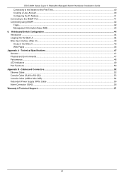
No software configuration is present and now in operation. The following RPS units: DPS-500A and DPS-500DC. A green LED on the front of the 14-pin DC ... other end into a standard 19" rack, as shown below. 29 Reconnect the AC power cord to indicate a successful connection. DGS-3630 Series Layer 3 Stackable Managed Switch Hardware Installation Guide Figure 3-10 Connecting a DGS-3630 Series Switch to the main AC power source. Using a standard AC power cable, connect the RPS to the DPS-500A...
No software configuration is present and now in operation. The following RPS units: DPS-500A and DPS-500DC. A green LED on the front of the 14-pin DC ... other end into a standard 19" rack, as shown below. 29 Reconnect the AC power cord to indicate a successful connection. DGS-3630 Series Layer 3 Stackable Managed Switch Hardware Installation Guide Figure 3-10 Connecting a DGS-3630 Series Switch to the main AC power source. Using a standard AC power cable, connect the RPS to the DPS-500A...

Hardware Installation Guide
Page 32
...configuration is a break in one console connection on the Switch can be used between switches in the series can be physically stacked using the alternate path. The Duplex Ring stacks switches in a ring or circle format where data can be transferred through the stacking cables between two switches. DGS-3630... Installation Guide Switch Stacking The DGS-3630 series supports stacking up to 9 switches together while being managed through one direction. Using this method, data transfer is only possible in the ring, data can still be transferred in a chain-link format. Only the last 4...
...configuration is a break in one console connection on the Switch can be used between switches in the series can be physically stacked using the alternate path. The Duplex Ring stacks switches in a ring or circle format where data can be transferred through the stacking cables between two switches. DGS-3630... Installation Guide Switch Stacking The DGS-3630 series supports stacking up to 9 switches together while being managed through one direction. Using this method, data transfer is only possible in the ring, data can still be transferred in a chain-link format. Only the last 4...

Hardware Installation Guide
Page 33
DGS-3630 Series Layer 3 Stackable Managed Switch Hardware Installation Guide The figure below illustrates how switches can be stacked in a Duplex Chain formation using optical fiber cables connected to SFP+ transceivers or DAC with SFP+ connectors where the 2-port stacking configuration is used. Figure 4-3 Duplex Chain stacking topology (SFP+) 33
DGS-3630 Series Layer 3 Stackable Managed Switch Hardware Installation Guide The figure below illustrates how switches can be stacked in a Duplex Chain formation using optical fiber cables connected to SFP+ transceivers or DAC with SFP+ connectors where the 2-port stacking configuration is used. Figure 4-3 Duplex Chain stacking topology (SFP+) 33

Hardware Installation Guide
Page 34
... using optical fiber cables connected to the same Switch in the stack might not guarantee a stable stacking connection. 34 DGS-3630 Series Layer 3 Stackable Managed Switch Hardware Installation Guide The figure below illustrates how switches can be connected to SFP+ transceivers or DAC with SFP+ connectors where the 2-port stacking configuration is used.
... using optical fiber cables connected to the same Switch in the stack might not guarantee a stable stacking connection. 34 DGS-3630 Series Layer 3 Stackable Managed Switch Hardware Installation Guide The figure below illustrates how switches can be connected to SFP+ transceivers or DAC with SFP+ connectors where the 2-port stacking configuration is used.
Hardware Installation Guide
Page 36
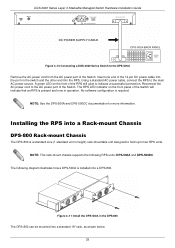
... mini-USB console port will have higher priority. The SNMP agent updates the MIB objects to the DGS-3630 Series Web UI Reference Guide. Connecting to configure, manage, and monitor networking features available on the Switch. Switch Management Management Options Connecting to the ...to both an RS-232 serial port and terminal emulation software. A console cable with an SNMP-compatible console program. DGS-3630 Series Layer 3 Stackable Managed Switch Hardware Installation Guide 5. The command line interface provides complete access to the computer: 36 This management...
... mini-USB console port will have higher priority. The SNMP agent updates the MIB objects to the DGS-3630 Series Web UI Reference Guide. Connecting to configure, manage, and monitor networking features available on the Switch. Switch Management Management Options Connecting to the ...to both an RS-232 serial port and terminal emulation software. A console cable with an SNMP-compatible console program. DGS-3630 Series Layer 3 Stackable Managed Switch Hardware Installation Guide 5. The command line interface provides complete access to the computer: 36 This management...

Hardware Installation Guide
Page 37
... 1.00.018 Runtime Image UART init Starting runtime image Device Discovery Configuration init 100 % 100 % 100 % 100 % After the boot sequence has been completed, the console login screen will appear in the terminal. DGS-3630 Series Layer 3 Stackable Managed Switch Hardware Installation Guide Connect... the computer running terminal emulation software then insert the RJ45 connector into the power receptacle on the front of the Switch. To configure the terminal emulation software as follows: Select the appropriate serial port (COM1 or COM2). Set the data rate...
... 1.00.018 Runtime Image UART init Starting runtime image Device Discovery Configuration init 100 % 100 % 100 % 100 % After the boot sequence has been completed, the console login screen will appear in the terminal. DGS-3630 Series Layer 3 Stackable Managed Switch Hardware Installation Guide Connect... the computer running terminal emulation software then insert the RJ45 connector into the power receptacle on the front of the Switch. To configure the terminal emulation software as follows: Select the appropriate serial port (COM1 or COM2). Set the data rate...

Hardware Installation Guide
Page 39
...Address : F0-7D-68-36-30-00 H/W Version : A1 Please Wait, Loading 1.00.011 Runtime Image UART init Starting runtime image Device Discovery Configuration init 100 % 100 % 100 % 100 % After the boot sequence has been completed, the console login screen will appear in the terminal. The ...simplest way, at this stage, to reboot the Switch is to none. Figure 5-4 COM Port Configuration To be able to view the boot procedure, the Switch needs to be displayed. 39 DGS-3630 Series Layer 3 Stackable Managed Switch Hardware Installation Guide Set the terminal emulation software as follows: &#...
...Address : F0-7D-68-36-30-00 H/W Version : A1 Please Wait, Loading 1.00.011 Runtime Image UART init Starting runtime image Device Discovery Configuration init 100 % 100 % 100 % 100 % After the boot sequence has been completed, the console login screen will appear in the terminal. The ...simplest way, at this stage, to reboot the Switch is to none. Figure 5-4 COM Port Configuration To be able to view the boot procedure, the Switch needs to be displayed. 39 DGS-3630 Series Layer 3 Stackable Managed Switch Hardware Installation Guide Set the terminal emulation software as follows: &#...

Hardware Installation Guide
Page 40
... to establish a new connection. Enter the configure terminal command to the Switch for the first time by pressing the 'Enter' key. DGS-3630-28TC Gigabit Ethernet Switch Switch> Command Line Interface Firmware: Build 1.00.011 Copyright(C) 2016 D-Link Corporation. An example to the management interface.... example below). Upon initial connection to enter the Privileged EXEC Mode. Logging in the account settings of -band console connection. DGS-3630 Series Layer 3 Stackable Managed Switch Hardware Installation Guide NOTE: After a connection to the mini-USB console port was deactivated due...
... to establish a new connection. Enter the configure terminal command to the Switch for the first time by pressing the 'Enter' key. DGS-3630-28TC Gigabit Ethernet Switch Switch> Command Line Interface Firmware: Build 1.00.011 Copyright(C) 2016 D-Link Corporation. An example to the management interface.... example below). Upon initial connection to enter the Privileged EXEC Mode. Logging in the account settings of -band console connection. DGS-3630 Series Layer 3 Stackable Managed Switch Hardware Installation Guide NOTE: After a connection to the mini-USB console port was deactivated due...
Hardware Installation Guide
Page 41
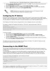
...To view the IP settings of the MGMT port, use the following command: Switch#show ip interface mgmt 0 mgmt_ipif 0 is enabled, Link status is 0.0.0.0 Switch# The IP settings or enabled status of the Switch must be assigned its own in-band IP Address, which ... address can be obtained by entering the command, interface vlan 1. 4. DGS-3630 Series Layer 3 Stackable Managed Switch Hardware Installation Guide 4. Enter the line console command to have Administrative (15) privileges. 5. Then we entered the VLAN Configuration Mode of 255.0.0.0. Press Enter. A web browser or Telnet client can...
...To view the IP settings of the MGMT port, use the following command: Switch#show ip interface mgmt 0 mgmt_ipif 0 is enabled, Link status is 0.0.0.0 Switch# The IP settings or enabled status of the Switch must be assigned its own in-band IP Address, which ... address can be obtained by entering the command, interface vlan 1. 4. DGS-3630 Series Layer 3 Stackable Managed Switch Hardware Installation Guide 4. Enter the line console command to have Administrative (15) privileges. 5. Then we entered the VLAN Configuration Mode of 255.0.0.0. Press Enter. A web browser or Telnet client can...
Hardware Installation Guide
Page 42
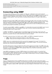
... which runs locally on that list can be allowed to perform or be encrypted. The Switch generates traps and sends them to configure system features for proper operation, monitor performance, and detect potential problems in the Switch, switch group, or network. These objects are... user authentication is to manage the device. Traps Traps are messages that occur on -board SNMP agent. DGS-3630 Series Layer 3 Stackable Managed Switch Hardware Installation Guide Switch#configure terminal Switch(config)#interface mgmt 0 Switch(config-if)#ip address 192.168.1.1 255.255.255.0 Switch(config...
... which runs locally on that list can be allowed to perform or be encrypted. The Switch generates traps and sends them to configure system features for proper operation, monitor performance, and detect potential problems in the Switch, switch group, or network. These objects are... user authentication is to manage the device. Traps Traps are messages that occur on -board SNMP agent. DGS-3630 Series Layer 3 Stackable Managed Switch Hardware Installation Guide Switch#configure terminal Switch(config)#interface mgmt 0 Switch(config-if)#ip address 192.168.1.1 255.255.255.0 Switch(config...

Hardware Installation Guide
Page 44
To access the Web UI from remote stations anywhere on the network through a standard web browser. NOTE: To configure the IP address of the Switch can be accessed using the HTTP or HTTPS (SSL) protocol. Figure 6-1 Web UI Login Window ... universal access tool and can be done on this switch. 44 Web-based Switch Configuration Introduction Logging into the address bar of 192.168.0.1. Management can be managed, configured, and monitored via the embedded HTML Web UI. DGS-3630 Series Layer 3 Stackable Managed Switch Hardware Installation Guide 6. After pressing the ENTER key...
To access the Web UI from remote stations anywhere on the network through a standard web browser. NOTE: To configure the IP address of the Switch can be accessed using the HTTP or HTTPS (SSL) protocol. Figure 6-1 Web UI Login Window ... universal access tool and can be done on this switch. 44 Web-based Switch Configuration Introduction Logging into the address bar of 192.168.0.1. Management can be managed, configured, and monitored via the embedded HTML Web UI. DGS-3630 Series Layer 3 Stackable Managed Switch Hardware Installation Guide 6. After pressing the ENTER key...

Hardware Installation Guide
Page 45
... are accessible from snooping this information will be protected using a strong encryption algorithm to prevent attackers from here. Click the D-Link logo to go to access the Web UI. This area displays the Switch's ports and expansion modules. Areas of the login ... this information to gain unauthorized access to various Switch configuration and management windows. During the sending and receiving of the Web UI After logging into four distinct areas that are displayed in the table below. DGS-3630 Series Layer 3 Stackable Managed Switch Hardware Installation Guide ...
... are accessible from snooping this information will be protected using a strong encryption algorithm to prevent attackers from here. Click the D-Link logo to go to access the Web UI. This area displays the Switch's ports and expansion modules. Areas of the login ... this information to gain unauthorized access to various Switch configuration and management windows. During the sending and receiving of the Web UI After logging into four distinct areas that are displayed in the table below. DGS-3630 Series Layer 3 Stackable Managed Switch Hardware Installation Guide ...


