User Manual
Page 3
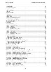
Table of Contents D-Link Web Smart Switch User Manual SNMP Settings ...20 Web-based Management ...21 Tool Bar > Save Menu ...22 Save Configuration ...22 Save Log ...22 Tool Bar > Tool Menu ...22 Reset ...22 Reset System ...22 Reboot Device ...23 Configuration ... > Online Help...24 Function Tree ...26 Device Information...26 System > System Settings ...27 System > Password...28 System > Port Settings ...28 System > DHCP Auto Configuration ...29 System > SysLog Host Settings ...30 System > Time Profile ...30 System > Power Saving ...31 System > IEEE802.3az EEE settings...31 VLAN > 802.1Q VLAN...
Table of Contents D-Link Web Smart Switch User Manual SNMP Settings ...20 Web-based Management ...21 Tool Bar > Save Menu ...22 Save Configuration ...22 Save Log ...22 Tool Bar > Tool Menu ...22 Reset ...22 Reset System ...22 Reboot Device ...23 Configuration ... > Online Help...24 Function Tree ...26 Device Information...26 System > System Settings ...27 System > Password...28 System > Port Settings ...28 System > DHCP Auto Configuration ...29 System > SysLog Host Settings ...30 System > Time Profile ...30 System > Power Saving ...31 System > IEEE802.3az EEE settings...31 VLAN > 802.1Q VLAN...
User Manual
Page 5
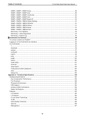
... Support...105 Emission (EMI) Certifications ...105 Safety Certifications...105 Features ...105 L2 Features ...105 L3 Features ...106 D-Link Green Technology ...106 VLAN ...106 QoS (Quality of Contents D-Link Web Smart Switch User Manual SNMP > SNMP > SNMP Group ...89 SNMP > SNMP > SNMP View ...89 SNMP...SNMP > RMON > RMON Alarm ...91 SNMP > RMON > RMON Event...92 Monitoring > Port Statistics...93 Monitoring > Cable Diagnostics ...93 Monitoring > System Log...94 6 Command Line Interface...95 To connect a switch via TELNET:...95 Logging on to the Command Line Interface 95 CLI Commands: ...95 ...
... Support...105 Emission (EMI) Certifications ...105 Safety Certifications...105 Features ...105 L2 Features ...105 L3 Features ...106 D-Link Green Technology ...106 VLAN ...106 QoS (Quality of Contents D-Link Web Smart Switch User Manual SNMP > SNMP > SNMP Group ...89 SNMP > SNMP > SNMP View ...89 SNMP...SNMP > RMON > RMON Alarm ...91 SNMP > RMON > RMON Event...92 Monitoring > Port Statistics...93 Monitoring > Cable Diagnostics ...93 Monitoring > System Log...94 6 Command Line Interface...95 To connect a switch via TELNET:...95 Logging on to the Command Line Interface 95 CLI Commands: ...95 ...

User Manual
Page 6
...Link and the D-LINK logo are trademarks of D-Link Corporation; D-Link Corporation disclaims any manner whatever without notice. © 2011 D-Link Corporation. Getting Started: A startup guide for detailed information about the function descriptions and configuration settings. Smart Console Utility: An introduction to the central management system... marks and names or their products. About This Guide D-Link Web Smart Switch User Manual About This Guide This guide provides instructions to install the D-Link Gigabit SmartPro Switch DGS-1500-20/28/28P/52, how to use of the device.
...Link and the D-LINK logo are trademarks of D-Link Corporation; D-Link Corporation disclaims any manner whatever without notice. © 2011 D-Link Corporation. Getting Started: A startup guide for detailed information about the function descriptions and configuration settings. Smart Console Utility: An introduction to the central management system... marks and names or their products. About This Guide D-Link Web Smart Switch User Manual About This Guide This guide provides instructions to install the D-Link Gigabit SmartPro Switch DGS-1500-20/28/28P/52, how to use of the device.

User Manual
Page 9
... is either sending or receiving data to the port. When optical transceiver is inserted to SFP port and link up when the Switch reaches the maximum power budget defined by the administrator via PoE System Settings page of Web GUI or the default power budget of 78 Watts. When a port has an...: The Pwr Max LED lights up , the RJ-45 port cannot be lost . Port Link/Act/Speed LED (1-24, 25F, 26F, 27F, 28F): The Link/Act/Speed LED flashes, which indicates a network link through the corresponding port. NOTE: On DGS-1500-28P, the SFP ports are shared with normal RJ-45 ports 25 to connect...
... is either sending or receiving data to the port. When optical transceiver is inserted to SFP port and link up when the Switch reaches the maximum power budget defined by the administrator via PoE System Settings page of Web GUI or the default power budget of 78 Watts. When a port has an...: The Pwr Max LED lights up , the RJ-45 port cannot be lost . Port Link/Act/Speed LED (1-24, 25F, 26F, 27F, 28F): The Link/Act/Speed LED flashes, which indicates a network link through the corresponding port. NOTE: On DGS-1500-28P, the SFP ports are shared with normal RJ-45 ports 25 to connect...
User Manual
Page 15
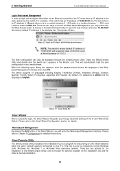
... the password is admin and the language is a program for computers running Windows 2000, Windows XP, Windows 7, or Windows Vista operating systems. There are two ways to your web browser. The web configuration can also be accessed through the autorun program on the installation CD ...SmartConsole Utility included in the address bar. When the following logon dialog box appears, enter the password and choose the language of the D-Link Web Smart Switch. This will enter the Web-based Management interface. Figure 3.3 - one is through the SmartConsole Utility. Web-based ...
... the password is admin and the language is a program for computers running Windows 2000, Windows XP, Windows 7, or Windows Vista operating systems. There are two ways to your web browser. The web configuration can also be accessed through the autorun program on the installation CD ...SmartConsole Utility included in the address bar. When the following logon dialog box appears, enter the password and choose the language of the D-Link Web Smart Switch. This will enter the Web-based Management interface. Figure 3.3 - one is through the SmartConsole Utility. Web-based ...
User Manual
Page 19
... for the next time the SmartConsole Utility is used. Here you can configure the Product Name, MAC Address, IPv4 Address, Subnet Mask, Gateway, System Name, Location, Trap IP, Group Interval, and DHCP Client Setting of the Device List in the Confirm Password box and then click OK. 14... To apply the configuration, insert the correct device password in an appointed filename and file path. 4 SmartConsole Utility D-Link Web Smart Switch User Manual Figure 4.5 - Save As: Records the setting of the Switch. SmartConsole Monitor List Save: Records the setting of ...
... for the next time the SmartConsole Utility is used. Here you can configure the Product Name, MAC Address, IPv4 Address, Subnet Mask, Gateway, System Name, Location, Trap IP, Group Interval, and DHCP Client Setting of the Device List in the Confirm Password box and then click OK. 14... To apply the configuration, insert the correct device password in an appointed filename and file path. 4 SmartConsole Utility D-Link Web Smart Switch User Manual Figure 4.5 - Save As: Records the setting of the Switch. SmartConsole Monitor List Save: Records the setting of ...

User Manual
Page 22
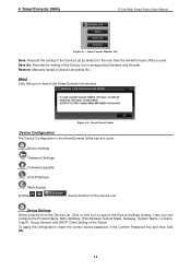
...17 Monitor: Click the Monitor button and the SmartConsole will appear . The in the monitor means the device was detected as system log or trap to choose a switch for configuration settings. Subnet Mask: Displays the Subnet Mask setting of the appointed device.... Displays the location of the device. 4 SmartConsole Utility D-Link Web Smart Switch User Manual Figure 4.11 - SmartConsole Add device Figure 4.12 - SmartConsole Device List Definitions of the device. System Name: Displays the appointed device system name. SNMP: Displays the SNMP status of the Device ...
...17 Monitor: Click the Monitor button and the SmartConsole will appear . The in the monitor means the device was detected as system log or trap to choose a switch for configuration settings. Subnet Mask: Displays the Subnet Mask setting of the appointed device.... Displays the location of the device. 4 SmartConsole Utility D-Link Web Smart Switch User Manual Figure 4.11 - SmartConsole Add device Figure 4.12 - SmartConsole Device List Definitions of the device. System Name: Displays the appointed device system name. SNMP: Displays the SNMP status of the Device ...
User Manual
Page 25
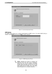
Click Enabled and then click Apply to quickly enable/disable the SNMP function. See Login Webbased Management for a detailed description. 20 5 Configuration D-Link Web Smart Switch User Manual Figure 5.2 - Figure 5.3 - SNMP Setting in the Web browser again and make it effective. Please enter ...the correct IP address in Smart Wizard NOTE: Changing the system IP address will disconnect you to make sure your PC is Disabled. The default SNMP...
Click Enabled and then click Apply to quickly enable/disable the SNMP function. See Login Webbased Management for a detailed description. 20 5 Configuration D-Link Web Smart Switch User Manual Figure 5.2 - Figure 5.3 - SNMP Setting in the Web browser again and make it effective. Please enter ...the correct IP address in Smart Wizard NOTE: Changing the system IP address will disconnect you to make sure your PC is Disabled. The default SNMP...
User Manual
Page 27
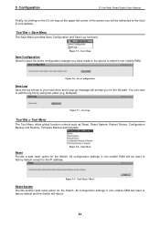
... Log Tool Bar > Tool Menu The Tool Menu offers global function controls such as Reset, Reset System, Reboot Device, Configuration Backup and Restore, Firmware Backup and Upgrade. 5 Configuration D-Link Web Smart Switch User Manual Finally, by using text editor (e.g. Figure 5.8 - Tool Menu > Reset... Reset System Provide another safe reset option for the Switch. Tool Bar > Save Menu ...
... Log Tool Bar > Tool Menu The Tool Menu offers global function controls such as Reset, Reset System, Reboot Device, Configuration Backup and Restore, Firmware Backup and Upgrade. 5 Configuration D-Link Web Smart Switch User Manual Finally, by using text editor (e.g. Figure 5.8 - Tool Menu > Reset... Reset System Provide another safe reset option for the Switch. Tool Bar > Save Menu ...

User Manual
Page 28
... to / restore from your disk. Click Browse to your local drive. Tool Menu > Reset System Reboot Device Provide a safe way to restart the switch. Click Reboot to reboot the system. Select IPv4 or IPv6 and specify TFTP Server IP Address and TFTP File Name for a saved... to or from . Figure 5.11 - The maximum Telnet Server connection is a file transfer protocol that allows you want to restore. 5 Configuration D-Link Web Smart Switch User Manual Figure 5.10 - Two methods can be selected: HTTP or TFTP. Tool Menu > Configure Backup and Restore HTTP: Backup...
... to / restore from your disk. Click Browse to your local drive. Tool Menu > Reset System Reboot Device Provide a safe way to restart the switch. Click Reboot to reboot the system. Select IPv4 or IPv6 and specify TFTP Server IP Address and TFTP File Name for a saved... to or from . Figure 5.11 - The maximum Telnet Server connection is a file transfer protocol that allows you want to restore. 5 Configuration D-Link Web Smart Switch User Manual Figure 5.10 - Two methods can be selected: HTTP or TFTP. Tool Menu > Configure Backup and Restore HTTP: Backup...
User Manual
Page 31
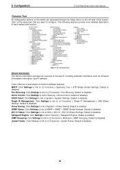
... L3 Functions > Single IP Management > SIM Global Settings. Default is enabled. DHCP Client: Click Settings to link to System > Power Saving. Power Saving: Click Settings to link to System > System Settings. Default is disabled. The following sections provide more detailed description of the switch, including essential information such as firmware & hardware information, and IP address...
... L3 Functions > Single IP Management > SIM Global Settings. Default is enabled. DHCP Client: Click Settings to link to System > Power Saving. Power Saving: Click Settings to link to System > System Settings. Default is disabled. The following sections provide more detailed description of the switch, including essential information such as firmware & hardware information, and IP address...
User Manual
Page 32
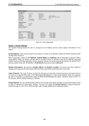
... other Web-Smart devices on the LAN. Group Interval: The D-Link Web Smart Switch will first look for a specific time span in order to configure the IP address and the basic system information of the Switch. Selective range is no action for a DHCP...Static and DHCP (Dynamic Host Configuration Protocol). Device Information System > System Settings The System Setting allows the user to maintain the information integrity. The user can more easily be manually configured. System Information: By entering a System Name and System Location, the device can adjust the Group Interval to...
... other Web-Smart devices on the LAN. Group Interval: The D-Link Web Smart Switch will first look for a specific time span in order to configure the IP address and the basic system information of the Switch. Selective range is no action for a DHCP...Static and DHCP (Dynamic Host Configuration Protocol). Device Information System > System Settings The System Setting allows the user to maintain the information integrity. The user can more easily be manually configured. System Information: By entering a System Name and System Location, the device can adjust the Group Interval to...

User Manual
Page 33
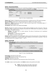
5 Configuration D-Link Web Smart Switch User Manual Figure 5.18 - System > Port Settings In the Port Setting page, the status of ports (From Port and To Port), the Speed can be set for all ports can ... latest information. 28 New Password: Enter the new password that you wish to access Administrator Level privileges on the Switch. Press the Refresh button to 20 characters. System > Password To set the Password, set a password of the device. The user may set the following parameters and click Apply: Old Password: If a password...
5 Configuration D-Link Web Smart Switch User Manual Figure 5.18 - System > Port Settings In the Port Setting page, the status of ports (From Port and To Port), the Speed can be set for all ports can ... latest information. 28 New Password: Enter the new password that you wish to access Administrator Level privileges on the Switch. Press the Refresh button to 20 characters. System > Password To set the Password, set a password of the device. The user may set the following parameters and click Apply: Old Password: If a password...

User Manual
Page 34
...3x flow control, half-duplex ports use Medium dependent interface crossover (MDIX) interface. To accomplish this function to properly match the connection. System > Port Settings Speed: Gigabit Fiber connections can enable this , the DHCP server must be used on the Network Interface Card (NIC)...match up . When enabled, the Switch becomes a DHCP client and gets the configuration file from the Switch. 5 Configuration D-Link Web Smart Switch User Manual Figure 5.20 - Copper connections can be set as an MDI port in Forced Mode settings (1000M Full, 100M Full, 100M Half, 10M...
...3x flow control, half-duplex ports use Medium dependent interface crossover (MDIX) interface. To accomplish this function to properly match the connection. System > Port Settings Speed: Gigabit Fiber connections can enable this , the DHCP server must be used on the Network Interface Card (NIC)...match up . When enabled, the Switch becomes a DHCP client and gets the configuration file from the Switch. 5 Configuration D-Link Web Smart Switch User Manual Figure 5.20 - Copper connections can be set as an MDI port in Forced Mode settings (1000M Full, 100M Full, 100M Half, 10M...
User Manual
Page 35
...are three levels. There are sent to a single server. Informational - All - Only one facility can be assigned (Local 0 ~ Local 7). System > Time Profile Settings Profile Name: Specifies the profile name. To set after current time, otherwise it will take effect on the next cycle time...are : Warning - If a second facility level is assigned, the first facility is 514. Figure 5.22 - 5 Configuration D-Link Web Smart Switch User Manual System > SysLog Host Settings The SysLog Host Settings page allows user to send Syslog messages to up to eight facilities can be ...
...are three levels. There are sent to a single server. Informational - All - Only one facility can be assigned (Local 0 ~ Local 7). System > Time Profile Settings Profile Name: Specifies the profile name. To set after current time, otherwise it will take effect on the next cycle time...are : Warning - If a second facility level is assigned, the first facility is 514. Figure 5.22 - 5 Configuration D-Link Web Smart Switch User Manual System > SysLog Host Settings The SysLog Host Settings page allows user to send Syslog messages to up to eight facilities can be ...

User Manual
Page 36
...the same as LED.) Therefore, if the Port Shut-off , Port Standby or System Hibernation. Each port on after Time Profile time's up event. System Hibernation - 5 Configuration D-Link Web Smart Switch User Manual System > Power Saving The Power Saving mode feature reduces power consumption automatically when the RJ... power-saving figures since main chipsets (both MAC and PHY) are disabled for a wake up when the state is used (less than 20 meters). Port Shut-off , the profile function will be Enabled or Disabled. Time Profile 2: Specifies the time profile or None. Click ...
...the same as LED.) Therefore, if the Port Shut-off , Port Standby or System Hibernation. Each port on after Time Profile time's up event. System Hibernation - 5 Configuration D-Link Web Smart Switch User Manual System > Power Saving The Power Saving mode feature reduces power consumption automatically when the RJ... power-saving figures since main chipsets (both MAC and PHY) are disabled for a wake up when the state is used (less than 20 meters). Port Shut-off , the profile function will be Enabled or Disabled. Time Profile 2: Specifies the time profile or None. Click ...

User Manual
Page 37
... R&D, Marketing), usage groups (such as e-mail), or multicast groups (multimedia applications such as Untag, Tag, or Not Member. To save the VID group, click Apply. System > IEEE802.3az EEE settings From Port / To Port: A consecutive group of ports that can be anywhere in the network, but communicate as 1, no default name...one VID. A port can be untagged in the same area. VLAN > 802.1Q VLAN A VLAN is a group of ports may change any physical connections. 5 Configuration D-Link Web Smart Switch User Manual Figure 5.25 - You may be easily organized to delete the VLAN group.
... R&D, Marketing), usage groups (such as e-mail), or multicast groups (multimedia applications such as Untag, Tag, or Not Member. To save the VID group, click Apply. System > IEEE802.3az EEE settings From Port / To Port: A consecutive group of ports that can be anywhere in the network, but communicate as 1, no default name...one VID. A port can be untagged in the same area. VLAN > 802.1Q VLAN A VLAN is a group of ports may change any physical connections. 5 Configuration D-Link Web Smart Switch User Manual Figure 5.25 - You may be easily organized to delete the VLAN group.
User Manual
Page 41
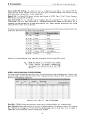
...VLAN OUI Setting page. Auto Detection: Switch will auto generate an ACL profile (Profile ID: 51) for all the Voice VLAN rules. System will add ports to enhance the VoIP service. Use the drop-down menu to configure the user-defined voice traffic's OUI. This identifier... uniquely identifies a vendor, manufacturer, or other organization. 5 Configuration D-Link Web Smart Switch User Manual Voice VLAN OUI Settings: this allows the user to enable or disable the OUI auto detection function. It will ...
...VLAN OUI Setting page. Auto Detection: Switch will auto generate an ACL profile (Profile ID: 51) for all the Voice VLAN rules. System will add ports to enhance the VoIP service. Use the drop-down menu to configure the user-defined voice traffic's OUI. This identifier... uniquely identifies a vendor, manufacturer, or other organization. 5 Configuration D-Link Web Smart Switch User Manual Voice VLAN OUI Settings: this allows the user to enable or disable the OUI auto detection function. It will ...
User Manual
Page 43
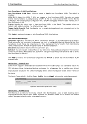
...There are another five surveillance components that could be configured to be studied. L2 Functions > Jumbo Frame Jumbo Frame support is 5. 5 Configuration D-Link Web Smart Switch User Manual Auto Surveillance VLAN Global Settings: Auto Surveillance VLAN State: Select to refresh the Auto Surveillance VLAN summary table. The ...Highest, High, Medium and Low. Figure 5.37 - VLAN ID: By default, the VLAN ID 4094 was created as Auto Surveillance VLAN. System will be tagged uplink port or downlink port for the component type. This enables network managers to turn on the device.
...There are another five surveillance components that could be configured to be studied. L2 Functions > Jumbo Frame Jumbo Frame support is 5. 5 Configuration D-Link Web Smart Switch User Manual Auto Surveillance VLAN Global Settings: Auto Surveillance VLAN State: Select to refresh the Auto Surveillance VLAN summary table. The ...Highest, High, Medium and Low. Figure 5.37 - VLAN ID: By default, the VLAN ID 4094 was created as Auto Surveillance VLAN. System will be tagged uplink port or downlink port for the component type. This enables network managers to turn on the device.

User Manual
Page 54
...VLAN in unregistered group. Figure 5.54 - L2 Functions > SNTP > Time Settings Clock Source: Specify the clock source by which the system time is set locally by the Switch to make the change effective. If choosing SNTP for the switch, and the following parameters can ... group will be forwarded based on the register table in the Time Settings page. Indicates that the system time is retrieved from which the system time is retrieved. 49 5 Configuration D-Link Web Smart Switch User Manual L2 Functions > Multicast > Multicast Filtering Mode The Multicast Filtering Mode function...
...VLAN in unregistered group. Figure 5.54 - L2 Functions > SNTP > Time Settings Clock Source: Specify the clock source by which the system time is set locally by the Switch to make the change effective. If choosing SNTP for the switch, and the following parameters can ... group will be forwarded based on the register table in the Time Settings page. Indicates that the system time is retrieved from which the system time is retrieved. 49 5 Configuration D-Link Web Smart Switch User Manual L2 Functions > Multicast > Multicast Filtering Mode The Multicast Filtering Mode function...