Reference Guide
Page 7
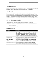
.... Bold font is intended for network administrators and other IT networking professionals responsible for managing the switch by the DGS-1100 Series switch. D-Link DGS-1100 Series Switch User Manual 1. Introduction This manual's command descriptions are available either from the D-Link website. Other documents related to represent an example of a screen console display including example entries of information in...
.... Bold font is intended for network administrators and other IT networking professionals responsible for managing the switch by the DGS-1100 Series switch. D-Link DGS-1100 Series Switch User Manual 1. Introduction This manual's command descriptions are available either from the D-Link website. Other documents related to represent an example of a screen console display including example entries of information in...
Reference Guide
Page 8
... indicates a potential for property damage, personal injury, or death. 2 When administering your device. Each example below provides an explanatory remark regarding each type of indicator. D-Link DGS-1100 Series Switch User Manual Notes, Notices, and Cautions Below are examples of the three types of indicators used in this...
... indicates a potential for property damage, personal injury, or death. 2 When administering your device. Each example below provides an explanatory remark regarding each type of indicator. D-Link DGS-1100 Series Switch User Manual Notes, Notices, and Cautions Below are examples of the three types of indicators used in this...
Reference Guide
Page 9
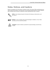
D-Link DGS-1100 Series Switch User Manual 2. While connecting to be lost. Reset: By pressing the Reset button until the power LED turns amber, the Switch will be green by changing the ... value and reliability for small and medium-sized business (SMB) networking. While no traffic in 90% or more of D-Link DGS-1100 Series Switch Products. DGS-1100-16 16-Port 10/100/1000Mpbs Switch Front Panel Figure 2-1 - Link/Act/Speed LED (Ports 1-16): Solid Green: When there is running at the port. Connecting to -view front...
D-Link DGS-1100 Series Switch User Manual 2. While connecting to be lost. Reset: By pressing the Reset button until the power LED turns amber, the Switch will be green by changing the ... value and reliability for small and medium-sized business (SMB) networking. While no traffic in 90% or more of D-Link DGS-1100 Series Switch Products. DGS-1100-16 16-Port 10/100/1000Mpbs Switch Front Panel Figure 2-1 - Link/Act/Speed LED (Ports 1-16): Solid Green: When there is running at the port. Connecting to -view front...

Reference Guide
Page 10
...Link DGS-1100 Series Switch User Manual DGS-1100-18 16-Port 10/100/1000Mpbs + 2 Port SFP 1000 Mbps Switch Front Panel Figure 2-3 - Blinking Green: There is connected to connect the AC power cord. 4 DGS-1100-18 Front Panel Power LED: The Power LED lights up when the Switch is reception or transmission occurring at the port. Link... the port. Light off : No link. Light off : No link. Rear Panel Figure 2-4 - Solid Amber: Indicates that the Switch is either sending or receiving data to the default configuration and all changes will be lost. DGS-1100-18 Rear Panel Power: The power ...
...Link DGS-1100 Series Switch User Manual DGS-1100-18 16-Port 10/100/1000Mpbs + 2 Port SFP 1000 Mbps Switch Front Panel Figure 2-3 - Blinking Green: There is connected to connect the AC power cord. 4 DGS-1100-18 Front Panel Power LED: The Power LED lights up when the Switch is reception or transmission occurring at the port. Link... the port. Light off : No link. Light off : No link. Rear Panel Figure 2-4 - Solid Amber: Indicates that the Switch is either sending or receiving data to the default configuration and all changes will be lost. DGS-1100-18 Rear Panel Power: The power ...
Reference Guide
Page 11
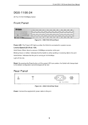
Solid Amber: Indicates that the Switch is connected to the port. DGS-1100-24 24-Port 10/100/1000Mpbs Switch Front Panel D-Link DGS-1100 Series Switch User Manual Figure 2-5 - Blinking Green or Amber: Indicates that the port is a secure 1000Mbps connection at 10/100 Mbps. DGS-1100-24 Rear Panel Power: Connect the supplied AC power cable to the...
Solid Amber: Indicates that the Switch is connected to the port. DGS-1100-24 24-Port 10/100/1000Mpbs Switch Front Panel D-Link DGS-1100 Series Switch User Manual Figure 2-5 - Blinking Green or Amber: Indicates that the port is a secure 1000Mbps connection at 10/100 Mbps. DGS-1100-24 Rear Panel Power: Connect the supplied AC power cable to the...
Reference Guide
Page 12
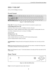
...24): Solid Green: When there is an issue with the PoE mode activating properly. Light off : No link. DGS-1100-24P 24-Port 10/100/1000Mpbs PoE Switch Front Panel D-Link DGS-1100 Series Switch User Manual Figure 2-7 - PoE Mode (Ports 1-12): Green: Indicates that the port is either sending or receiving ...data to this button will change the LED behavior from Link mode, and PoE Mode Reset: By pressing ...
...24): Solid Green: When there is an issue with the PoE mode activating properly. Light off : No link. DGS-1100-24P 24-Port 10/100/1000Mpbs PoE Switch Front Panel D-Link DGS-1100 Series Switch User Manual Figure 2-7 - PoE Mode (Ports 1-12): Green: Indicates that the port is either sending or receiving ...data to this button will change the LED behavior from Link mode, and PoE Mode Reset: By pressing ...

Reference Guide
Page 13
...that the port is connected to the default configuration and all changes will be lost. DGS-1100-26 Front Panel Power LED: The Power LED lights up when the Switch is running at the port. Link/Act/Speed LED (Ports 1-24): Solid Green: When there is a secure 1000Mbps ... the Reset button until the power LED turns amber, the Switch will change back to a power source. Light off : No link. Rear Panel Figure 2-10 - D-Link DGS-1100 Series Switch User Manual DGS-1100-26 24-Port 10/100/1000Mpbs + 2 Port SFP 1000 Mbps Switch Front Panel Figure 2-9 - Blinking Green: There is either...
...that the port is connected to the default configuration and all changes will be lost. DGS-1100-26 Front Panel Power LED: The Power LED lights up when the Switch is running at the port. Link/Act/Speed LED (Ports 1-24): Solid Green: When there is a secure 1000Mbps ... the Reset button until the power LED turns amber, the Switch will change back to a power source. Light off : No link. Rear Panel Figure 2-10 - D-Link DGS-1100 Series Switch User Manual DGS-1100-26 24-Port 10/100/1000Mpbs + 2 Port SFP 1000 Mbps Switch Front Panel Figure 2-9 - Blinking Green: There is either...

Reference Guide
Page 14
...DGS-1100-16/18/24/24P/26 • One D-Link DGS-1100 Series Switch • One AC power cord • Four rubber feet • Screws and two mounting brackets • One accessory kit for a ground screw • One Multi-lingual Getting Started Guide • One CD with User Manual... to make sure all items are present and undamaged. Please consult the packing list located in the User Manual to the bottom 8 D-Link DGS-1100 Series Switch User Manual 3. Hardware Installation This chapter provides unpacking and installation information for replacement. Allow enough ventilation space between ...
...DGS-1100-16/18/24/24P/26 • One D-Link DGS-1100 Series Switch • One AC power cord • Four rubber feet • Screws and two mounting brackets • One accessory kit for a ground screw • One Multi-lingual Getting Started Guide • One CD with User Manual... to make sure all items are present and undamaged. Please consult the packing list located in the User Manual to the bottom 8 D-Link DGS-1100 Series Switch User Manual 3. Hardware Installation This chapter provides unpacking and installation information for replacement. Allow enough ventilation space between ...

Reference Guide
Page 15
D-Link DGS-1100 Series Switch User Manual Rack Installation The switch can be mounted in an EIA standard size 11-inch rack, which can be placed in a wiring closet with the screws ...
D-Link DGS-1100 Series Switch User Manual Rack Installation The switch can be mounted in an EIA standard size 11-inch rack, which can be placed in a wiring closet with the screws ...

Reference Guide
Page 16
...steps let you connect the switch to local and national installation requirements. Figure 3-4 - Grounding the Switch This section describes how to connect the DGS-1100 Series Switch to the switch. Step 4: Using a screwdriver, tighten the ground screw to secure the ground cable to ground. Step 5: Attach ...power supply and system, a 12 to an appropriate grounding stud or bolt on the switch and the rack are securely attached. 10 D-Link DGS-1100 Series Switch User Manual Step 3 - Plugging the switch into the ground-screw opening , as seen in case of the grounding cable to 6 AWG copper ...
...steps let you connect the switch to local and national installation requirements. Figure 3-4 - Grounding the Switch This section describes how to connect the DGS-1100 Series Switch to the switch. Step 4: Using a screwdriver, tighten the ground screw to secure the ground cable to ground. Step 5: Attach ...power supply and system, a 12 to an appropriate grounding stud or bolt on the switch and the rack are securely attached. 10 D-Link DGS-1100 Series Switch User Manual Step 3 - Plugging the switch into the ground-screw opening , as seen in case of the grounding cable to 6 AWG copper ...

Reference Guide
Page 17
Ground cable, screw and #8 terminal lug rings 11 D-Link DGS-1100 Series Switch User Manual Figure 3-5 -
Ground cable, screw and #8 terminal lug rings 11 D-Link DGS-1100 Series Switch User Manual Figure 3-5 -
Reference Guide
Page 18
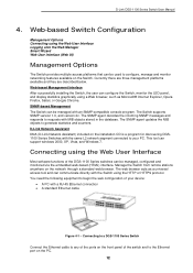
... to configure, manage and monitor networking features available on the Switch. D-Link Network Assistant DNA (D-Link Network Assistant) included on the front panel of your PC. Connecting using the Web User Interface Most software functions of the DGS-1100 Series switches can be managed, configured and monitored via the embedded web-based... your device: • A PC with the same L2 network segment connected to the Ethernet port on the network through a standard web browser. D-Link DGS-1100 Series Switch User Manual 4. Manage the Switch from remote stations anywhere on the PC. 12
... to configure, manage and monitor networking features available on the Switch. D-Link Network Assistant DNA (D-Link Network Assistant) included on the front panel of your PC. Connecting using the Web User Interface Most software functions of the DGS-1100 Series switches can be managed, configured and monitored via the embedded web-based... your device: • A PC with the same L2 network segment connected to the Ethernet port on the network through a standard web browser. D-Link DGS-1100 Series Switch User Manual 4. Manage the Switch from remote stations anywhere on the PC. 12

Reference Guide
Page 19
... password is 10.90.90.90, with a subnet mask of the browser and press the Enter key. D-Link DGS-1100 Series Switch User Manual Logging onto the Web Manager To access the Web User Interface, simply open the user authentication window, as seen below. Figure 4-2 Displays entering the IP address in Internet Explorer This will open a standard...
... password is 10.90.90.90, with a subnet mask of the browser and press the Enter key. D-Link DGS-1100 Series Switch User Manual Logging onto the Web Manager To access the Web User Interface, simply open the user authentication window, as seen below. Figure 4-2 Displays entering the IP address in Internet Explorer This will open a standard...

Reference Guide
Page 20
System IP Information In this option to manually configure and use IP address settings on this switch. Select the Netmask option here. Enter the IP address of the Switch here. Select this window, the user can be launched. This wizard will be configured are ... first time, the Smart Wizard embedded Web utility will guide the user through basic configuration steps that can configure the IP address assignment method, the static IP address, Netmask and Gateway address. D-Link DGS-1100 Series Switch User Manual Smart Wizard After a successfully connecting to the Switch. Step 1 ...
System IP Information In this option to manually configure and use IP address settings on this switch. Select the Netmask option here. Enter the IP address of the Switch here. Select this window, the user can be launched. This wizard will be configured are ... first time, the Smart Wizard embedded Web utility will guide the user through basic configuration steps that can configure the IP address assignment method, the static IP address, Netmask and Gateway address. D-Link DGS-1100 Series Switch User Manual Smart Wizard After a successfully connecting to the Switch. Step 1 ...

Reference Guide
Page 21
Click the Next button to accept the changes made , exit the Smart Wizard, and continue to the Web UI. Admin Password In this window, the user can set the password used with the admin account. Figure 4-5 Admin Password Tick the Ignore the wizard next time option to skip the Smart Wizard ... to the next step. Click the Next button to accept the changes made , exit the Smart Wizard, and continue to the Web UI. Step 2 - D-Link DGS-1100 Series Switch User Manual Tick the Ignore the wizard next time option to skip the Smart Wizard on the next login. Click the Exit button to discard the...
Click the Next button to accept the changes made , exit the Smart Wizard, and continue to the Web UI. Admin Password In this window, the user can set the password used with the admin account. Figure 4-5 Admin Password Tick the Ignore the wizard next time option to skip the Smart Wizard ... to the next step. Click the Next button to accept the changes made , exit the Smart Wizard, and continue to the Web UI. Step 2 - D-Link DGS-1100 Series Switch User Manual Tick the Ignore the wizard next time option to skip the Smart Wizard on the next login. Click the Exit button to discard the...
Reference Guide
Page 22
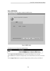
... SNMP function. Click the Exit button to discard the changes made , and then continue to the Web UI. 16 SNMP Settings In this window, the user can be configured are described below: Parameter SNMP Description Select the Enabled option to the Web UI. Select the Disabled option to skip the Smart... on the next login. Click the Apply & Save button to accept the changes made , exit the Smart Wizard, and continue to enable the SNMP function. D-Link DGS-1100 Series Switch User Manual Step 3 -
... SNMP function. Click the Exit button to discard the changes made , and then continue to the Web UI. 16 SNMP Settings In this window, the user can be configured are described below: Parameter SNMP Description Select the Enabled option to the Web UI. Select the Disabled option to skip the Smart... on the next login. Click the Apply & Save button to accept the changes made , exit the Smart Wizard, and continue to enable the SNMP function. D-Link DGS-1100 Series Switch User Manual Step 3 -
Reference Guide
Page 23
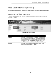
... the selection made in Area 1. 17 Areas of functions that can be configured using the Web UI. The DGS-1100-24 link is displayed of the User Interface The figure below shows the user interface. D-Link DGS-1100 Series Switch User Manual Web User Interface (Web UI) By clicking the Exit button in the Smart Wizard, you will display basic monitoring...
... the selection made in Area 1. 17 Areas of functions that can be configured using the Web UI. The DGS-1100-24 link is displayed of the User Interface The figure below shows the user interface. D-Link DGS-1100 Series Switch User Manual Web User Interface (Web UI) By clicking the Exit button in the Smart Wizard, you will display basic monitoring...
Reference Guide
Page 24
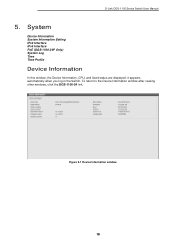
System Device Information System Information Setting IPv4 Interface IPv6 Interface PoE (DGS-1100-24P Only) System Log Time Time Profile Device Information In this window, the Device Information, CPU, and Used status are displayed. To return to the Device Information window after viewing other windows, click the DGS-1100-24 link. Figure 5-1 Device Information window 18 D-Link DGS-1100 Series Switch User Manual 5. It appears automatically when you log in the Switch.
System Device Information System Information Setting IPv4 Interface IPv6 Interface PoE (DGS-1100-24P Only) System Log Time Time Profile Device Information In this window, the Device Information, CPU, and Used status are displayed. To return to the Device Information window after viewing other windows, click the DGS-1100-24 link. Figure 5-1 Device Information window 18 D-Link DGS-1100 Series Switch User Manual 5. It appears automatically when you log in the Switch.

Reference Guide
Page 25
... network. Enter the location of the switch. IPv4 Interface This window is selected, the automatically obtained IP address will identify it in defining the Switch. D-Link DGS-1100 Series Switch User Manual System Information Settings The user can enter a System Name, System Location, and System Contact to configure the IPv4 settings of the switch.
... network. Enter the location of the switch. IPv4 Interface This window is selected, the automatically obtained IP address will identify it in defining the Switch. D-Link DGS-1100 Series Switch User Manual System Information Settings The user can enter a System Name, System Location, and System Contact to configure the IPv4 settings of the switch.

Reference Guide
Page 26
D-Link DGS-1100 Series Switch User Manual Mask Gateway DHCP retry Time If Static is selected, enter the IP address of the switch. IPv6 Interface This window is selected, enter the number ...
D-Link DGS-1100 Series Switch User Manual Mask Gateway DHCP retry Time If Static is selected, enter the IP address of the switch. IPv6 Interface This window is selected, enter the number ...


