Product Manual
Page 2
D-Link EasySmart Switch User Manual Table of Contents Table of Contents ...i About This Guide...1 Terms/Usage...1 Copyright and Trademarks ...1 Product Introduction ...2 DGS-1100-16 ...2 Front Panel ...2 Rear Panel...2 DGS-1100-24 ...3 Front Panel ...3 Rear Panel...3 Hardware Installation ...4 Step 1: Unpacking...4 Step 2: Switch Installation...4 ......12 Help ...12 Device Configuration...12 Add(+), Delete(-) and Discover the device 14 Device List...15 Configuration ...16 Web-based Management...16 Tool Bar > Save Menu ...17 Save Configuration ...17 Tool Bar > Tool Menu ...17 Reboot Device ...17...
D-Link EasySmart Switch User Manual Table of Contents Table of Contents ...i About This Guide...1 Terms/Usage...1 Copyright and Trademarks ...1 Product Introduction ...2 DGS-1100-16 ...2 Front Panel ...2 Rear Panel...2 DGS-1100-24 ...3 Front Panel ...3 Rear Panel...3 Hardware Installation ...4 Step 1: Unpacking...4 Step 2: Switch Installation...4 ......12 Help ...12 Device Configuration...12 Add(+), Delete(-) and Discover the device 14 Device List...15 Configuration ...16 Web-based Management...16 Tool Bar > Save Menu ...17 Save Configuration ...17 Tool Bar > Tool Menu ...17 Reboot Device ...17...
Product Manual
Page 3
... ...35 Emission (EMI) Certifications ...35 Safety Certifications...35 Features ...35 L2 Features ...35 VLAN ...35 QoS (Quality of Service)...36 Management...36 Appendix C - D-Link EasySmart Switch User Manual System > System Settings ...20 System > Port Settings...21 System > Trap Settings For SmartConsole 21 System > Password Access Control ...22 L2 Features > Port Trunking...22...
... ...35 Emission (EMI) Certifications ...35 Safety Certifications...35 Features ...35 L2 Features ...35 VLAN ...35 QoS (Quality of Service)...36 Management...36 Appendix C - D-Link EasySmart Switch User Manual System > System Settings ...20 System > Port Settings...21 System > Trap Settings For SmartConsole 21 System > Password Access Control ...22 L2 Features > Port Trunking...22...
Product Manual
Page 4
... step-by -step hardware installation procedures. 2. Note: The model you have purchased may be used in the document. D-Link EasySmart Switch User Manual About This Guide This guide provides instructions to install the D-Link Gigabit Ethernet EasySmart Switch DGS-1100-16/24, how to use of the device. Reproduction in any proprietary interest in this text...
... step-by -step hardware installation procedures. 2. Note: The model you have purchased may be used in the document. D-Link EasySmart Switch User Manual About This Guide This guide provides instructions to install the D-Link Gigabit Ethernet EasySmart Switch DGS-1100-16/24, how to use of the device. Reproduction in any proprietary interest in this text...
Product Manual
Page 5
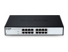
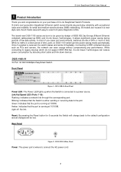
D-Link EasySmart Switch User Manual 1 Product Introduction Thank you and congratulations on DGS-1100 switch get into power saving mode automatically. It allows significant power saving during periods of D-Link EasySmart Switch Products. In most of use cases and environments, switches.... DGS-1100-16 16-Port 10/100/1000Mpbs EasySmart Switch Front Panel Figure 1 - Blinking: Indicates that the Switch is running at 1000M. Link/Act/Speed LED (Ports 1-16): Flashing: Indicates a network link through the corresponding port. Light off: No link. Rear Panel Figure 2 - D-Link's ...
D-Link EasySmart Switch User Manual 1 Product Introduction Thank you and congratulations on DGS-1100 switch get into power saving mode automatically. It allows significant power saving during periods of D-Link EasySmart Switch Products. In most of use cases and environments, switches.... DGS-1100-16 16-Port 10/100/1000Mpbs EasySmart Switch Front Panel Figure 1 - Blinking: Indicates that the Switch is running at 1000M. Link/Act/Speed LED (Ports 1-16): Flashing: Indicates a network link through the corresponding port. Light off: No link. Rear Panel Figure 2 - D-Link's ...
Product Manual
Page 6
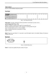
... that the port is connected to the port. Link/Act/Speed LED (Ports 1-24): Flashing: Indicates a network link through the corresponding port. Green: Indicates that the port is either sending or receiving data to a power source. DGS-1100-24 Front Panel Power LED: The Power LED lights... up when the Switch is running at 1000M. Reset: Press the reset button for 5 seconds to reset the Switch back to this port. 3 Light off: No link. DGS-1100-24 24-Port 10/100/1000Mpbs EasySmart Switch Front Panel D-Link EasySmart Switch User Manual...
... that the port is connected to the port. Link/Act/Speed LED (Ports 1-24): Flashing: Indicates a network link through the corresponding port. Green: Indicates that the port is either sending or receiving data to a power source. DGS-1100-24 Front Panel Power LED: The Power LED lights... up when the Switch is running at 1000M. Reset: Press the reset button for 5 seconds to reset the Switch back to this port. 3 Light off: No link. DGS-1100-24 24-Port 10/100/1000Mpbs EasySmart Switch Front Panel D-Link EasySmart Switch User Manual...
Product Manual
Page 7
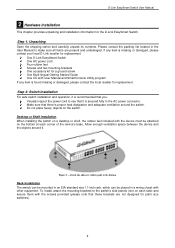
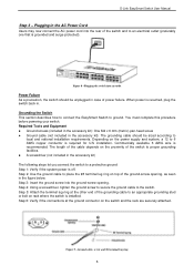
...equipment. Attach the adhesive rubber pads to the bottom Rack Installation The switch can be mounted in the User Manual to the AC power connector. One D-Link EasySmart Switch One AC power cord Four rubber feet Screws and two mounting brackets One accessory kit for a ...switch's side panels (one on the switch. Allow enough ventilation space between the device and the objects around the switch. D-Link EasySmart Switch User Manual 2 Hardware Installation This chapter provides unpacking and installation information for replacement. Please consult the packing list located in an EIA standard...
...equipment. Attach the adhesive rubber pads to the bottom Rack Installation The switch can be mounted in the User Manual to the AC power connector. One D-Link EasySmart Switch One AC power cord Four rubber feet Screws and two mounting brackets One accessory kit for a ...switch's side panels (one on the switch. Allow enough ventilation space between the device and the objects around the switch. D-Link EasySmart Switch User Manual 2 Hardware Installation This chapter provides unpacking and installation information for replacement. Please consult the packing list located in an EIA standard...
Product Manual
Page 8
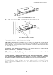
... may be such that overloading of equipment nameplate ratings should be greater than direct connections to installing the equipment in the rack should be maintained. D-Link EasySmart Switch User Manual Figure 6 -
... may be such that overloading of equipment nameplate ratings should be greater than direct connections to installing the equipment in the rack should be maintained. D-Link EasySmart Switch User Manual Figure 6 -
Product Manual
Page 9
... an outlet Power Failure As a precaution, the switch should be unplugged in the figure below. Figure 9 -Ground cable, screw and #8 terminal lug ring 6 D-Link EasySmart Switch User Manual Step 3 - Depending on the proximity of the grounding cable to proper grounding facilities. A screwdriver (not included in the accessory kit): The grounding cable...
... an outlet Power Failure As a precaution, the switch should be unplugged in the figure below. Figure 9 -Ground cable, screw and #8 terminal lug ring 6 D-Link EasySmart Switch User Manual Step 3 - Depending on the proximity of the grounding cable to proper grounding facilities. A screwdriver (not included in the accessory kit): The grounding cable...

Product Manual
Page 10
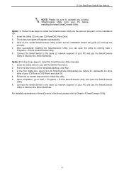
...through any port on the PC. 7 A PC with Web-Based Management. Please refer to the following equipment to manage multiple D-Link EasySmart Switches, the SmartConsole Utility is used for the Web-based Management and the SmartConsole Utility. Each switch can be assigned its ...own IP Address, which is a more convenient choice. Management Options The D-Link EasySmart Switch can allow one user to initialize multiple EasySmart Switches. D-Link EasySmart Switch User Manual 3 Getting Started This chapter introduces the management interface of the switch and to the Web...
...through any port on the PC. 7 A PC with Web-Based Management. Please refer to the following equipment to manage multiple D-Link EasySmart Switches, the SmartConsole Utility is used for the Web-based Management and the SmartConsole Utility. Each switch can be assigned its ...own IP Address, which is a more convenient choice. Management Options The D-Link EasySmart Switch can allow one user to initialize multiple EasySmart Switches. D-Link EasySmart Switch User Manual 3 Getting Started This chapter introduces the management interface of the switch and to the Web...
Product Manual
Page 11
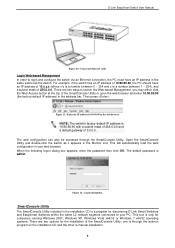
... bar. When the following logon dialog box appears, enter the password then click OK. The default password is manual installation. 8 There are two options for discovering D-Link Smart Switches and EasySmart Switches within the same L2 network segment connected to your web browser. Then press . ...The SmartConsole Utility included in the same subnet as it appears in your PC. one is through the SmartConsole Utility. D-Link EasySmart Switch User Manual Figure 10 -Connected Ethernet cable Login Web-based Management In order to login and configure the switch via an Ethernet connection,...
... bar. When the following logon dialog box appears, enter the password then click OK. The default password is manual installation. 8 There are two options for discovering D-Link Smart Switches and EasySmart Switches within the same L2 network segment connected to your web browser. Then press . ...The SmartConsole Utility included in the same subnet as it appears in your PC. one is through the SmartConsole Utility. D-Link EasySmart Switch User Manual Figure 10 -Connected Ethernet cable Login Web-based Management In order to login and configure the switch via an Ethernet connection,...
Product Manual
Page 12
..., go to uninstall any existing SmartConsole Utility from your PC and use the SmartConsole Utility to install the SmartConsole Utility manually. 1. Click on the Windows desktop, click Run. 3. From the Start menu on the "Install SmartConsole Utility" button and... an installation wizard will appear automatically. 3. D-Link EasySmart Switch User Manual NOTE: Please be sure to Start > Programs > D-Link SmartConsole Utility and open the utility by clicking Start > Programs > D-Link SmartConsole Utility. 5. For detailed explanations of your CD-Rom or ...
..., go to uninstall any existing SmartConsole Utility from your PC and use the SmartConsole Utility to install the SmartConsole Utility manually. 1. Click on the Windows desktop, click Run. 3. From the Start menu on the "Install SmartConsole Utility" button and... an installation wizard will appear automatically. 3. D-Link EasySmart Switch User Manual NOTE: Please be sure to Start > Programs > D-Link SmartConsole Utility and open the utility by clicking Start > Programs > D-Link SmartConsole Utility. 5. For detailed explanations of your CD-Rom or ...
Product Manual
Page 13
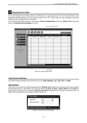
... include 15 secs, 30 secs, 1mins, 2mins, and 5 mins for selecting the monitoring time intervals. Figure 14- D-Link EasySmart Switch User Manual 4 SmartConsole Utility The D-Link SmartConsole Utility allows the administrator to quickly discover all D-Link Smart Switches and EasySmart Switches which were selected as the main body, and SmartConsole Settings at the left...
... include 15 secs, 30 secs, 1mins, 2mins, and 5 mins for selecting the monitoring time intervals. Figure 14- D-Link EasySmart Switch User Manual 4 SmartConsole Utility The D-Link SmartConsole Utility allows the administrator to quickly discover all D-Link Smart Switches and EasySmart Switches which were selected as the main body, and SmartConsole Settings at the left...
Product Manual
Page 14
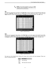
... to launch the Trap window. Click Clear Log to clear all entries. Click OK to exit Figure 16 - Click Clear Trap to clear all log entries. Please see below for detailed description. D-Link EasySmart Switch User Manual NOTE: If the Group Interval is set to 0, IGMP Snooping must be disabled in the SmartConsole...
... to launch the Trap window. Click Clear Log to clear all entries. Click OK to exit Figure 16 - Click Clear Trap to clear all log entries. Please see below for detailed description. D-Link EasySmart Switch User Manual NOTE: If the Group Interval is set to 0, IGMP Snooping must be disabled in the SmartConsole...
Product Manual
Page 15
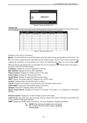
... IP, and DHCP Client Setting of the Device List in an appointed filename and file path. Here you will see below options: D-Link EasySmart Switch User Manual Figure 17 - Monitor Load: Manually load a Device List setting file. Click on this icon to launch the Device Settings window. Figure 18 - Monitor Save As: Records...
... IP, and DHCP Client Setting of the Device List in an appointed filename and file path. Here you will see below options: D-Link EasySmart Switch User Manual Figure 17 - Monitor Load: Manually load a Device List setting file. Click on this icon to launch the Device Settings window. Figure 18 - Monitor Save As: Records...
Product Manual
Page 16
..." after completion, and "Fail" is firmware upgrade fails or cannot be completed for one or many switches of device, and then click Upgrade. D-Link EasySmart Switch User Manual Figure 19 - Therefore, ensure to launch the Firmware Upgrade window. Here you are going to maintain the connection between the devices and SmartConsole Utility...
..." after completion, and "Fail" is firmware upgrade fails or cannot be completed for one or many switches of device, and then click Upgrade. D-Link EasySmart Switch User Manual Figure 19 - Therefore, ensure to launch the Firmware Upgrade window. Here you are going to maintain the connection between the devices and SmartConsole Utility...
Product Manual
Page 17
D-Link EasySmart Switch User Manual Figure 21 - Enter the correct Device Password and then click OK. Figure 22 - Click the + and insert a device IP address to remove it means the ...
D-Link EasySmart Switch User Manual Figure 21 - Enter the correct Device Password and then click OK. Figure 22 - Click the + and insert a device IP address to remove it means the ...
Product Manual
Page 18
...(in the monitor means the device was detected as system log or trap to the SmartConsole Utility. This feature is disconnected. . D-Link EasySmart Switch User Manual Figure 24 - Please check if the power or IP Address: Displays the current IP addresses of the Utility. DHCP: Specify if the... SmartConsole will become . SNMP: Displays the SNMP status of the device. Location: Displays where the appointed device location. LLDP: Displays the LLDP (Link Layer Discovery Protocol) status of the device. The icon will collect the trap and log data from a DHCP server. Figure 25 - This is...
...(in the monitor means the device was detected as system log or trap to the SmartConsole Utility. This feature is disconnected. . D-Link EasySmart Switch User Manual Figure 24 - Please check if the power or IP Address: Displays the current IP addresses of the Utility. DHCP: Specify if the... SmartConsole will become . SNMP: Displays the SNMP status of the device. Location: Displays where the appointed device location. LLDP: Displays the LLDP (Link Layer Discovery Protocol) status of the device. The icon will collect the trap and log data from a DHCP server. Figure 25 - This is...
Product Manual
Page 19
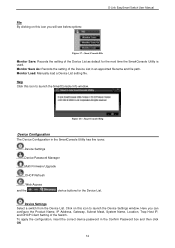
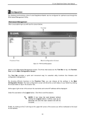
...16 By choosing different functions in the Main Configuration Screen. Under the username is the Web-based Management screen. Web-based Management Above is the Logout button. NOTE: If you can be configured for essential utility functions like firmware and configuration management. D-Link EasySmart Switch User Manual... 5 Configuration The features and functions of the D-Link EasySmart Switch can change all the settings in the Function Tree, you close...
...16 By choosing different functions in the Main Configuration Screen. Under the username is the Web-based Management screen. Web-based Management Above is the Logout button. NOTE: If you can be configured for essential utility functions like firmware and configuration management. D-Link EasySmart Switch User Manual... 5 Configuration The features and functions of the D-Link EasySmart Switch can change all the settings in the Function Tree, you close...
Product Manual
Page 20
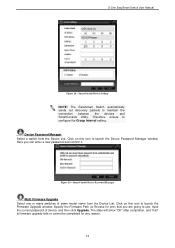
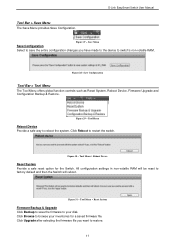
... save the entire configuration changes you want to reboot the system. Tool Menu > Reboot Device Reset System Provide a safe reset option for a saved firmware file. D-Link EasySmart Switch User Manual Tool Bar > Save Menu The Save Menu provides Save Configuration.
... save the entire configuration changes you want to reboot the system. Tool Menu > Reboot Device Reset System Provide a safe reset option for a saved firmware file. D-Link EasySmart Switch User Manual Tool Bar > Save Menu The Save Menu provides Save Configuration.
Product Manual
Page 21
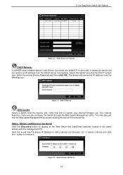
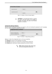
... Backup & Restore Allow the current configuration settings to or from device until upgrade is incomplete. The Switch may crash if the Firmware Upgrade is complete. D-Link EasySmart Switch User Manual Figure 32 -
... Backup & Restore Allow the current configuration settings to or from device until upgrade is incomplete. The Switch may crash if the Firmware Upgrade is complete. D-Link EasySmart Switch User Manual Figure 32 -

