
DGS-1100 Series Datasheet
Page 1
... cable length and adjust power usage accordingly. The DGS-1100 Series also supports Layer2 features such as IGMP snooping to EasySmart Switches featuring D-Link Green Technology. Energy Efficient Technology IEEE 802.3az EEE and D-Link Green 3.0 technology help reduce energy use and operating costs. DGS-1100-08/16/24 EasySmart Switch Series Features Energy Efficient Ethernet • IEEE 802...
... cable length and adjust power usage accordingly. The DGS-1100 Series also supports Layer2 features such as IGMP snooping to EasySmart Switches featuring D-Link Green Technology. Energy Efficient Technology IEEE 802.3az EEE and D-Link Green 3.0 technology help reduce energy use and operating costs. DGS-1100-08/16/24 EasySmart Switch Series Features Energy Efficient Ethernet • IEEE 802...

DGS-1100 Series Datasheet
Page 2
... instant access. By deploying EEE devices, users can cut operating costs and even cut down the affected port. DGS-1100-08/16/24 EasySmart Switch D-Link Green/Power Saving Performance Compliant with IEEE802.3az Energy Efficient Ethernet, these switches consume less energy by a specific port and automatically shuts down on necessary cooling equipment, helping small and...
... instant access. By deploying EEE devices, users can cut operating costs and even cut down the affected port. DGS-1100-08/16/24 EasySmart Switch D-Link Green/Power Saving Performance Compliant with IEEE802.3az Energy Efficient Ethernet, these switches consume less energy by a specific port and automatically shuts down on necessary cooling equipment, helping small and...
DGS-1100 Series Datasheet
Page 3
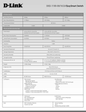
...; Static Trunk - 2 groups, 2-4 ports per group (DGS-1100-08) - 8 groups, 2-4 ports per port • VLAN Group - Weighted Round Robin (WRR) Strict - DGS-1100-08/16/24 EasySmart Switch Performance Switching Capacity Max. Tx Error - One-to -One (DGS-1100-16/24 only) • Cable Diagnostics Statistics - Power ... 1.73" (280mm x 180mm x 44 mm) 11-inch Desktop/Rackmount Size, 1U Height 1.25 lbs (566g) 3.3 lbs (1.5kg) Power (Per Device) Link/Activity/Speed (Per Port) FCC Class A, CE Class A, VCCI Class A UL/cUL, CE LVD 503,585 Hours 988,205 Hours 774,990 Hours •...
...; Static Trunk - 2 groups, 2-4 ports per group (DGS-1100-08) - 8 groups, 2-4 ports per port • VLAN Group - Weighted Round Robin (WRR) Strict - DGS-1100-08/16/24 EasySmart Switch Performance Switching Capacity Max. Tx Error - One-to -One (DGS-1100-16/24 only) • Cable Diagnostics Statistics - Power ... 1.73" (280mm x 180mm x 44 mm) 11-inch Desktop/Rackmount Size, 1U Height 1.25 lbs (566g) 3.3 lbs (1.5kg) Power (Per Device) Link/Activity/Speed (Per Port) FCC Class A, CE Class A, VCCI Class A UL/cUL, CE LVD 503,585 Hours 988,205 Hours 774,990 Hours •...

DGS-1100 Series Datasheet
Page 4
...; RFC 1945 HTTP/1.0 • RFC 2647 802.1p Desctiption EasySmart 8-Port Gigabit Switch EasySmart 16-Port Gigabit Switch EasySmart 24-Port Gigabit Switch DGS-1100-08 DGS-1100-16 DGS-1100-24 For more details. DGS-1100-8/16/24 EasySmart Switch Security Management D-Link Green RFC Standard List Warranty Warranty Ordering Information Product DGS-1100-08 DGS-1100-16 DGS-1100-24 QR CODES Scan Codes for more information U.S.A. | 17595 Mt.
...; RFC 1945 HTTP/1.0 • RFC 2647 802.1p Desctiption EasySmart 8-Port Gigabit Switch EasySmart 16-Port Gigabit Switch EasySmart 24-Port Gigabit Switch DGS-1100-08 DGS-1100-16 DGS-1100-24 For more details. DGS-1100-8/16/24 EasySmart Switch Security Management D-Link Green RFC Standard List Warranty Warranty Ordering Information Product DGS-1100-08 DGS-1100-16 DGS-1100-24 QR CODES Scan Codes for more information U.S.A. | 17595 Mt.

Manual
Page 2
...-based Management ...9 Supported Web Browsers ...9 Connecting to the Switch...9 Login Web-based Management ...10 SmartConsole Utility...10 4 ...Link EasySmart Switch User Manual Table of Contents Table of Contents ...i About This Guide ...1 Terms/Usage...1 Copyright and Trademarks ...1 1 Product Introduction ...2 DGS-1100-08 ...2 Front Panel ...2 Rear Panel...2 DGS-1100-16 ...3 Front Panel ...3 Rear Panel...3 DGS-1100-24 ...3 Front Panel ...3 Rear Panel...4 2 Hardware Installation ...5 Step 1: Unpacking...5 Packing contents of DGS-1100-08...5 Packing contents of DGS-1100-16/24...5 Step 2: Switch...
...-based Management ...9 Supported Web Browsers ...9 Connecting to the Switch...9 Login Web-based Management ...10 SmartConsole Utility...10 4 ...Link EasySmart Switch User Manual Table of Contents Table of Contents ...i About This Guide ...1 Terms/Usage...1 Copyright and Trademarks ...1 1 Product Introduction ...2 DGS-1100-08 ...2 Front Panel ...2 Rear Panel...2 DGS-1100-16 ...3 Front Panel ...3 Rear Panel...3 DGS-1100-24 ...3 Front Panel ...3 Rear Panel...4 2 Hardware Installation ...5 Step 1: Unpacking...5 Packing contents of DGS-1100-08...5 Packing contents of DGS-1100-16/24...5 Step 2: Switch...

Manual
Page 3
......38 Features ...38 L2 Features ...38 VLAN ...38 QoS (Quality of Service)...38 Management...38 Power Saving ...38 Appendix C - Rack mount Instructions ...39 ii D-Link EasySmart Switch User Manual Reboot Device ...19 Reset System ...19 Firmware Backup & Upgrade ...19 Configuration Backup & Restore ...20 Function Tree ...21 Device Information...21 System > System... Table > Static MAC 34 Security > MAC Address Table > Dynamic Forwarding Table 35 Appendix A - Ethernet Technology...37 Gigabit Ethernet Technology ...37 Fast Ethernet Technology ...37 Switching Technology ...37 Appendix B -
......38 Features ...38 L2 Features ...38 VLAN ...38 QoS (Quality of Service)...38 Management...38 Power Saving ...38 Appendix C - Rack mount Instructions ...39 ii D-Link EasySmart Switch User Manual Reboot Device ...19 Reset System ...19 Firmware Backup & Upgrade ...19 Configuration Backup & Restore ...20 Function Tree ...21 Device Information...21 System > System... Table > Static MAC 34 Security > MAC Address Table > Dynamic Forwarding Table 35 Appendix A - Ethernet Technology...37 Gigabit Ethernet Technology ...37 Fast Ethernet Technology ...37 Switching Technology ...37 Appendix B -

Manual
Page 4
... letter lower case) refers to other than its components, network connections, and technical specifications. All rights reserved. D-Link EasySmart Switch User Manual About This Guide This guide provides instructions to install the D-Link Gigabit Ethernet EasySmart Switch DGS-1100-08/16/24, how to use of the device. This guide is strictly forbidden. Microsoft and Windows are...
... letter lower case) refers to other than its components, network connections, and technical specifications. All rights reserved. D-Link EasySmart Switch User Manual About This Guide This guide provides instructions to install the D-Link Gigabit Ethernet EasySmart Switch DGS-1100-08/16/24, how to use of the device. This guide is strictly forbidden. Microsoft and Windows are...

Manual
Page 5
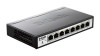
...which do not support IEEE 802.3az, D-Link Green Technologies can reduce power consumption by design of low data activity. DGS-1100-08 8-Port 10/100/1000Mpbs EasySmart Switch Front Panel Figure 1 - In most of D-Link EasySmart Switch Products. Blinking: Indicates that the port is ...running at 1000M. Rear Panel Figure 2 - While connecting to the port. DGS-1100-08 Front Panel Power LED:...
...which do not support IEEE 802.3az, D-Link Green Technologies can reduce power consumption by design of low data activity. DGS-1100-08 8-Port 10/100/1000Mpbs EasySmart Switch Front Panel Figure 1 - In most of D-Link EasySmart Switch Products. Blinking: Indicates that the port is ...running at 1000M. Rear Panel Figure 2 - While connecting to the port. DGS-1100-08 Front Panel Power LED:...

Manual
Page 6
... port is running at 10/100M. Amber: Indicates that the Switch is running at 1000M. DGS-1100-24 24-Port 10/100/1000Mpbs EasySmart Switch Front Panel Figure 5 - Light off: No link. Rear Panel Figure 4- DGS-1100-16 16-Port 10/100/1000Mpbs EasySmart Switch Front Panel D-Link EasySmart Switch User Manual Figure 3 - Green: Indicates that the port is either...
... port is running at 10/100M. Amber: Indicates that the Switch is running at 1000M. DGS-1100-24 24-Port 10/100/1000Mpbs EasySmart Switch Front Panel Figure 5 - Light off: No link. Rear Panel Figure 4- DGS-1100-16 16-Port 10/100/1000Mpbs EasySmart Switch Front Panel D-Link EasySmart Switch User Manual Figure 3 - Green: Indicates that the port is either...

Manual
Page 7
Amber: Indicates that the port is running at 1000M. Reset: Press the reset button for 5 seconds to reset the Switch back to this port. 4 Rear Panel Figure 6- DGS-1100-24 Rear Panel Power: Connect the supplied AC power cable to the default settings. Green: Indicates that the Switch is either sending or receiving data to the port. Light off: No link. All previous changes will be lost. D-Link EasySmart Switch User Manual Blinking: Indicates that the port is running at 10/100M.
Amber: Indicates that the port is running at 1000M. Reset: Press the reset button for 5 seconds to reset the Switch back to this port. 4 Rear Panel Figure 6- DGS-1100-24 Rear Panel Power: Connect the supplied AC power cable to the default settings. Green: Indicates that the Switch is either sending or receiving data to the port. Light off: No link. All previous changes will be lost. D-Link EasySmart Switch User Manual Blinking: Indicates that the port is running at 10/100M.

Manual
Page 8
... power connector. Make sure that screw on the D-Link EasySmart Switch One Multi-lingual Getting Started Guide One CD with User Manual and SmartConsole Utility program Packing contents of DGS-1100-16/24 One D-Link EasySmart Switch One AC power cord Four rubber feet Screws and ...CD with the device must be attached on the bottom at each corner of DGS-1100-08 One D-Link EasySmart Switch One AC Power Adapter Four rubber feet One accessory kit for replacement. D-Link EasySmart Switch User Manual 2 Hardware Installation This chapter provides unpacking and installation information for replacement...
... power connector. Make sure that screw on the D-Link EasySmart Switch One Multi-lingual Getting Started Guide One CD with User Manual and SmartConsole Utility program Packing contents of DGS-1100-16/24 One D-Link EasySmart Switch One AC power cord Four rubber feet Screws and ...CD with the device must be attached on the bottom at each corner of DGS-1100-08 One D-Link EasySmart Switch One AC Power Adapter Four rubber feet One accessory kit for replacement. D-Link EasySmart Switch User Manual 2 Hardware Installation This chapter provides unpacking and installation information for replacement...

Manual
Page 9
... Mounting of power strips)." 6 D) Circuit Overloading - use the screws provided with other than room ambient. D-Link EasySmart Switch User Manual Rack Installation The switch can be mounted in an EIA standard size 11-inch rack, which can be used when addressing this concern...should be such that a hazardous condition is not compromised. C) Mechanical Loading - Figure 9- Therefore, consideration should be given to the switch's side panels (one on overcurrent protection and supply wiring. E) Reliable Earthing - Reliable earthing of rack-mounted equipment should be greater...
... Mounting of power strips)." 6 D) Circuit Overloading - use the screws provided with other than room ambient. D-Link EasySmart Switch User Manual Rack Installation The switch can be mounted in an EIA standard size 11-inch rack, which can be used when addressing this concern...should be such that a hazardous condition is not compromised. C) Mechanical Loading - Figure 9- Therefore, consideration should be given to the switch's side panels (one on overcurrent protection and supply wiring. E) Reliable Earthing - Reliable earthing of rack-mounted equipment should be greater...

Manual
Page 10
...kit ) into a cement wall Step 2: Drive the T3 x 15L screws into the nylon screw anchors. Step 3: Hook the mounting holes of the switch back on the screws. Mounting on the bottom of power failure. Two mounting slots are provided on a wood wall Step 1: Drive the... screws into an outlet Power Failure As a precaution, the switch should be mounted on a wall. Figure 11 -Plugging the switch into a wood wall. Step 2. D-Link EasySmart Switch User Manual Wall-mount The Switch can be unplugged in case of the switch for this purpose. When power is grounded and surge protected)....
...kit ) into a cement wall Step 2: Drive the T3 x 15L screws into the nylon screw anchors. Step 3: Hook the mounting holes of the switch back on the screws. Mounting on the bottom of power failure. Two mounting slots are provided on a wood wall Step 1: Drive the... screws into an outlet Power Failure As a precaution, the switch should be mounted on a wall. Figure 11 -Plugging the switch into a wood wall. Step 2. D-Link EasySmart Switch User Manual Wall-mount The Switch can be unplugged in case of the switch for this purpose. When power is grounded and surge protected)....

Manual
Page 11
...opening , as seen in the accessory kit): The grounding cable should be sized according to the switch. Step 5: Attach the terminal lug ring at the ground connector on the switch and the rack are securely attached. Commercially available 6 AWG wire is recommended. Step 6: Verify if...or bolt on top of the cable depends on the power supply and system, a 12 to ground. D-Link EasySmart Switch User Manual Grounding the Switch This section describes how to connect the EasySmart Switch to 6 AWG copper conductor is required for U.S installation. Figure 12 -Ground cable, screw and #8 terminal...
...opening , as seen in the accessory kit): The grounding cable should be sized according to the switch. Step 5: Attach the terminal lug ring at the ground connector on the switch and the rack are securely attached. Commercially available 6 AWG wire is recommended. Step 6: Verify if...or bolt on top of the cable depends on the power supply and system, a 12 to ground. D-Link EasySmart Switch User Manual Grounding the Switch This section describes how to connect the EasySmart Switch to 6 AWG copper conductor is required for U.S installation. Figure 12 -Ground cable, screw and #8 terminal...

Manual
Page 12
...multiple EasySmart Switches. D-Link EasySmart Switch User Manual 3 Getting Started This chapter introduces the management interface of the switch and to the Ethernet port on the front panel of D-Link EasySmart Switch. Each switch can allow only one user to access to manage multiple D-Link EasySmart Switches, the ... your PC and it is used for the Web-based Management and the SmartConsole Utility. Management Options The D-Link EasySmart Switch can configure the Switch, monitor the network status, and display statistics using the Web-based Management or through any of the ports ...
...multiple EasySmart Switches. D-Link EasySmart Switch User Manual 3 Getting Started This chapter introduces the management interface of the switch and to the Ethernet port on the front panel of D-Link EasySmart Switch. Each switch can allow only one user to access to manage multiple D-Link EasySmart Switches, the ... your PC and it is used for the Web-based Management and the SmartConsole Utility. Management Options The D-Link EasySmart Switch can configure the Switch, monitor the network status, and display statistics using the Web-based Management or through any of the ports ...

Manual
Page 13
...a default gateway of 10.90.90.90, the PC should have an IP address in the same subnet as it appears in the address bar. D-Link EasySmart Switch User Manual Figure 13 -Connected Ethernet cable Login Web-based Management In order to login and configure the... of 10.x.y.z (where x/y is a number between 0 ~ 254 and z is a number between 1 ~ 254), and a subnet mask of 255.0.0.0. There are two options for discovering D-Link Smart Switches and EasySmart Switches within the same L2 network segment connected to launch the Web-based Management, you may either click the Web Access button at the top...
...a default gateway of 10.90.90.90, the PC should have an IP address in the same subnet as it appears in the address bar. D-Link EasySmart Switch User Manual Figure 13 -Connected Ethernet cable Login Web-based Management In order to login and configure the... of 10.x.y.z (where x/y is a number between 0 ~ 254 and z is a number between 1 ~ 254), and a subnet mask of 255.0.0.0. There are two options for discovering D-Link Smart Switches and EasySmart Switches within the same L2 network segment connected to launch the Web-based Management, you may either click the Web Access button at the top...

Manual
Page 14
... 2: Follow these steps to Start > Programs > D-Link SmartConsole Utility and open the folder. Upon completion, go to install the SmartConsole Utility via the autorun program on the Drive to discover the Smart Switches. D-Link EasySmart Switch User Manual NOTE: Please be sure to install the ...utility. 5. The autorun program will guide you can open the utility by clicking Start > Programs > D-Link SmartConsole Utility. 5. Connect the Smart Switch to the same L2 network...
... 2: Follow these steps to Start > Programs > D-Link SmartConsole Utility and open the folder. Upon completion, go to install the SmartConsole Utility via the autorun program on the Drive to discover the Smart Switches. D-Link EasySmart Switch User Manual NOTE: Please be sure to install the ...utility. 5. The autorun program will guide you can open the utility by clicking Start > Programs > D-Link SmartConsole Utility. 5. Connect the Smart Switch to the same L2 network...

Manual
Page 15
... Utility allows the administrator to quickly discover all D-Link Smart Switches and EasySmart Switches which were selected as the main body, and SmartConsole Settings at the left has five icons, Utility Settings, Log, Trap, File, and Help. Device ... Settings Click this icon to basic configurations of three parts, Device Configurations at the left . Utility Group Interval establishes the intervals (in seconds) that the Switch will be discovered in the Device List. Choices include 15 secs, 30 secs, 1mins, 2mins, and 5 mins for selecting the monitoring time intervals. Figure...
... Utility allows the administrator to quickly discover all D-Link Smart Switches and EasySmart Switches which were selected as the main body, and SmartConsole Settings at the left has five icons, Utility Settings, Log, Trap, File, and Help. Device ... Settings Click this icon to basic configurations of three parts, Device Configurations at the left . Utility Group Interval establishes the intervals (in seconds) that the Switch will be discovered in the Device List. Choices include 15 secs, 30 secs, 1mins, 2mins, and 5 mins for selecting the monitoring time intervals. Figure...

Manual
Page 16
... where it comes from and Status shows the content of this trap message. SmartConsole Trap The trap icon in the Switch or the switches will change while receiving new trap messages. D-Link EasySmart Switch User Manual NOTE: If the Group Interval is set to 0, IGMP Snooping must be disabled in the SmartConsole Settings will...
... where it comes from and Status shows the content of this trap message. SmartConsole Trap The trap icon in the Switch or the switches will change while receiving new trap messages. D-Link EasySmart Switch User Manual NOTE: If the Group Interval is set to 0, IGMP Snooping must be disabled in the SmartConsole Settings will...

Manual
Page 17
... this icon you can configure the Product Name, IP Address, Gateway, Subnet Mask, System Name, Location, Trap Host IP, and DHCP Client Setting of the Switch. 14 Help Click this icon to launch the SmartConsole Info window. SmartConsole File Monitor Save: Records the setting of the Device List in the SmartConsole... Utility is used. Monitor Save As: Records the setting of the Device List as default for the Device List. Here you will see below options: D-Link EasySmart Switch User Manual Figure 20- Figure 21- Device Settings Select...
... this icon you can configure the Product Name, IP Address, Gateway, Subnet Mask, System Name, Location, Trap Host IP, and DHCP Client Setting of the Switch. 14 Help Click this icon to launch the SmartConsole Info window. SmartConsole File Monitor Save: Records the setting of the Device List in the SmartConsole... Utility is used. Monitor Save As: Records the setting of the Device List as default for the Device List. Here you will see below options: D-Link EasySmart Switch User Manual Figure 20- Figure 21- Device Settings Select...

