
DGS-1100 Series Datasheet
Page 1
DGS-1100-08/16/24 EasySmart Switch Series Features Energy Efficient Ethernet • IEEE 802.3az compliant D-Link Green Technology • Power Saving by Link Status • Power Saving by Cable Length • Provides reliable and eco-friendly operation Advanced ...VLAN ensure security systems and telephone systems have highest priority. The DGS-1100 Series also supports Layer2 features such as IGMP snooping to EasySmart Switches featuring D-Link Green Technology. Surveillance VLAN and Bandwidth Control The DGS-1100 Series supports Surveillance VLAN, which is a new, industry leading ...
DGS-1100-08/16/24 EasySmart Switch Series Features Energy Efficient Ethernet • IEEE 802.3az compliant D-Link Green Technology • Power Saving by Link Status • Power Saving by Cable Length • Provides reliable and eco-friendly operation Advanced ...VLAN ensure security systems and telephone systems have highest priority. The DGS-1100 Series also supports Layer2 features such as IGMP snooping to EasySmart Switches featuring D-Link Green Technology. Surveillance VLAN and Bandwidth Control The DGS-1100 Series supports Surveillance VLAN, which is a new, industry leading ...

DGS-1100 Series Datasheet
Page 2
DGS-1100-08/16/24 EasySmart Switch D-Link Green/Power Saving Performance Compliant with IEEE802.3az Energy Efficient Ethernet, these switches consume less energy by a specific port and automatically shuts down the affected port. By deploying EEE devices, users can adjust power usage for shorter cable connections of cable error. The switches automatically detect the length of the connected...
DGS-1100-08/16/24 EasySmart Switch D-Link Green/Power Saving Performance Compliant with IEEE802.3az Energy Efficient Ethernet, these switches consume less energy by a specific port and automatically shuts down the affected port. By deploying EEE devices, users can adjust power usage for shorter cable connections of cable error. The switches automatically detect the length of the connected...
DGS-1100 Series Datasheet
Page 3
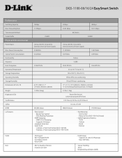
DGS-1100-08/16/24 EasySmart Switch Performance Switching Capacity Max. HOL Blocking Prevention • IGMP Snooping - Supports 32 Groups • Loopback Detection • Static Trunk - 2 groups, 2-4 ports per group (DGS-1100-08) - 8 groups, 2-4 ports per port • VLAN Group - Many-to -One - Supports 32 static VLAN ...x 1.73" (280mm x 180mm x 44 mm) 11-inch Desktop/Rackmount Size, 1U Height 1.25 lbs (566g) 3.3 lbs (1.5kg) Power (Per Device) Link/Activity/Speed (Per Port) FCC Class A, CE Class A, VCCI Class A UL/cUL, CE LVD 503,585 Hours 988,205 Hours 774,990 Hours • Flow...
DGS-1100-08/16/24 EasySmart Switch Performance Switching Capacity Max. HOL Blocking Prevention • IGMP Snooping - Supports 32 Groups • Loopback Detection • Static Trunk - 2 groups, 2-4 ports per group (DGS-1100-08) - 8 groups, 2-4 ports per port • VLAN Group - Many-to -One - Supports 32 static VLAN ...x 1.73" (280mm x 180mm x 44 mm) 11-inch Desktop/Rackmount Size, 1U Height 1.25 lbs (566g) 3.3 lbs (1.5kg) Power (Per Device) Link/Activity/Speed (Per Port) FCC Class A, CE Class A, VCCI Class A UL/cUL, CE LVD 503,585 Hours 988,205 Hours 774,990 Hours • Flow...

DGS-1100 Series Datasheet
Page 4
... BootP/DHCP client • RFC 1945 HTTP/1.0 • RFC 2647 802.1p Desctiption EasySmart 8-Port Gigabit Switch EasySmart 16-Port Gigabit Switch EasySmart 24-Port Gigabit Switch DGS-1100-08 DGS-1100-16 DGS-1100-24 For more Information • Static MAC - D-Link, and the D-Link logo, are the property of D-Link Corporation or its subsidiaries in the United States and/or other countries. Other trademarks...
... BootP/DHCP client • RFC 1945 HTTP/1.0 • RFC 2647 802.1p Desctiption EasySmart 8-Port Gigabit Switch EasySmart 16-Port Gigabit Switch EasySmart 24-Port Gigabit Switch DGS-1100-08 DGS-1100-16 DGS-1100-24 For more Information • Static MAC - D-Link, and the D-Link logo, are the property of D-Link Corporation or its subsidiaries in the United States and/or other countries. Other trademarks...

Manual
Page 2
...-based Management ...9 Supported Web Browsers ...9 Connecting to the Switch...9 Login Web-based Management ...10 SmartConsole Utility...10 4 ...Link EasySmart Switch User Manual Table of Contents Table of Contents ...i About This Guide ...1 Terms/Usage...1 Copyright and Trademarks ...1 1 Product Introduction ...2 DGS-1100-08 ...2 Front Panel ...2 Rear Panel...2 DGS-1100-16 ...3 Front Panel ...3 Rear Panel...3 DGS-1100-24 ...3 Front Panel ...3 Rear Panel...4 2 Hardware Installation ...5 Step 1: Unpacking...5 Packing contents of DGS-1100-08...5 Packing contents of DGS-1100-16/24...5 Step 2: Switch...
...-based Management ...9 Supported Web Browsers ...9 Connecting to the Switch...9 Login Web-based Management ...10 SmartConsole Utility...10 4 ...Link EasySmart Switch User Manual Table of Contents Table of Contents ...i About This Guide ...1 Terms/Usage...1 Copyright and Trademarks ...1 1 Product Introduction ...2 DGS-1100-08 ...2 Front Panel ...2 Rear Panel...2 DGS-1100-16 ...3 Front Panel ...3 Rear Panel...3 DGS-1100-24 ...3 Front Panel ...3 Rear Panel...4 2 Hardware Installation ...5 Step 1: Unpacking...5 Packing contents of DGS-1100-08...5 Packing contents of DGS-1100-16/24...5 Step 2: Switch...

Manual
Page 3
... VLAN ...38 QoS (Quality of Service)...38 Management...38 Power Saving ...38 Appendix C - Ethernet Technology...37 Gigabit Ethernet Technology ...37 Fast Ethernet Technology ...37 Switching Technology ...37 Appendix B - D-Link EasySmart Switch User Manual Reboot Device ...19 Reset System ...19 Firmware Backup & Upgrade ...19 Configuration Backup & Restore ...20 Function Tree ...21 Device Information...21 System...
... VLAN ...38 QoS (Quality of Service)...38 Management...38 Power Saving ...38 Appendix C - Ethernet Technology...37 Gigabit Ethernet Technology ...37 Fast Ethernet Technology ...37 Switching Technology ...37 Appendix B - D-Link EasySmart Switch User Manual Reboot Device ...19 Reset System ...19 Firmware Backup & Upgrade ...19 Configuration Backup & Restore ...20 Function Tree ...21 Device Information...21 System...

Manual
Page 4
.... A NOTE indicates important information that helps a better use the Web Utility, and to the central management system. 4. D-Link EasySmart Switch User Manual About This Guide This guide provides instructions to install the D-Link Gigabit Ethernet EasySmart Switch DGS-1100-08/16/24, how to use of the device. Smart Console Utility: An introduction to configure Web-based Management step...
.... A NOTE indicates important information that helps a better use the Web Utility, and to the central management system. 4. D-Link EasySmart Switch User Manual About This Guide This guide provides instructions to install the D-Link Gigabit Ethernet EasySmart Switch DGS-1100-08/16/24, how to use of the device. Smart Console Utility: An introduction to configure Web-based Management step...

Manual
Page 5
... period of time, ports on your purchase of D-Link EasySmart Switch Products. While no traffic in 90% or more of use cases and environments, switches are born to EEE compliant devices, such as EEE) and D-Link Green Technologies. While connecting to the port. DGS-1100-08 8-Port 10/100/1000Mpbs EasySmart Switch Front Panel Figure 1 - Blinking: Indicates that the port...
... period of time, ports on your purchase of D-Link EasySmart Switch Products. While no traffic in 90% or more of use cases and environments, switches are born to EEE compliant devices, such as EEE) and D-Link Green Technologies. While connecting to the port. DGS-1100-08 8-Port 10/100/1000Mpbs EasySmart Switch Front Panel Figure 1 - Blinking: Indicates that the port...

Manual
Page 6
...-Port 10/100/1000Mpbs EasySmart Switch Front Panel D-Link EasySmart Switch User Manual Figure 3 - Link/Act/Speed LED (Ports 1-16): Flashing: Indicates a network link through the corresponding port. 3 Green: Indicates that the port is connected to a power source. Light off: No link. Rear Panel Figure 4- DGS-1100-24 24-Port 10/100/1000Mpbs EasySmart Switch Front Panel Figure 5 - DGS-1100-24 Front Panel Power...
...-Port 10/100/1000Mpbs EasySmart Switch Front Panel D-Link EasySmart Switch User Manual Figure 3 - Link/Act/Speed LED (Ports 1-16): Flashing: Indicates a network link through the corresponding port. 3 Green: Indicates that the port is connected to a power source. Light off: No link. Rear Panel Figure 4- DGS-1100-24 24-Port 10/100/1000Mpbs EasySmart Switch Front Panel Figure 5 - DGS-1100-24 Front Panel Power...

Manual
Page 7
Amber: Indicates that the port is running at 10/100M. Rear Panel Figure 6- Green: Indicates that the Switch is either sending or receiving data to the port. Reset: Press the reset button for 5 seconds to reset the Switch back to this port. 4 DGS-1100-24 Rear Panel Power: Connect the supplied AC power cable to the default settings. Light off: No link. D-Link EasySmart Switch User Manual Blinking: Indicates that the port is running at 1000M. All previous changes will be lost.
Amber: Indicates that the port is running at 10/100M. Rear Panel Figure 6- Green: Indicates that the Switch is either sending or receiving data to the port. Reset: Press the reset button for 5 seconds to reset the Switch back to this port. 4 DGS-1100-24 Rear Panel Power: Connect the supplied AC power cable to the default settings. Light off: No link. D-Link EasySmart Switch User Manual Blinking: Indicates that the port is running at 1000M. All previous changes will be lost.

Manual
Page 8
... reseller for wall-mount installation One ground screw that screw on the switch. Packing contents of DGS-1100-08 One D-Link EasySmart Switch One AC Power Adapter Four rubber feet One accessory kit for replacement. Step 2: Switch Installation For safe switch installation and operation, it is recommended that you: Visually inspect the...desktop or shelf, the rubber feet included with the device must be attached on the bottom at each corner of DGS-1100-16/24 One D-Link EasySmart Switch One AC power cord Four rubber feet Screws and two mounting brackets One accessory kit for a ground screw One ...
... reseller for wall-mount installation One ground screw that screw on the switch. Packing contents of DGS-1100-08 One D-Link EasySmart Switch One AC Power Adapter Four rubber feet One accessory kit for replacement. Step 2: Switch Installation For safe switch installation and operation, it is recommended that you: Visually inspect the...desktop or shelf, the rubber feet included with the device must be attached on the bottom at each corner of DGS-1100-16/24 One D-Link EasySmart Switch One AC power cord Four rubber feet Screws and two mounting brackets One accessory kit for a ground screw One ...

Manual
Page 9
... the rack or chassis Please be aware of the equipment is not achieved due to uneven mechanical loading. D) Circuit Overloading - E) Reliable Earthing - D-Link EasySmart Switch User Manual Rack Installation The switch can be mounted in an EIA standard size 11-inch rack, which can be placed in a wiring closet with the equipment rack to...
... the rack or chassis Please be aware of the equipment is not achieved due to uneven mechanical loading. D) Circuit Overloading - E) Reliable Earthing - D-Link EasySmart Switch User Manual Rack Installation The switch can be mounted in an EIA standard size 11-inch rack, which can be placed in a wiring closet with the equipment rack to...

Manual
Page 10
Plugging in the AC Power Cord Users may now connect the AC power cord into the rear of the switch and to complete wall-mount process. Mounting on a cement wall Step 1: Mount the nylon screw anchors ø5 x 22L mm (included in the accessory kit ...1: Drive the T3 x 15L screws into an outlet Power Failure As a precaution, the switch should be mounted on the bottom of the switch for this purpose. Two mounting slots are provided on a wall. D-Link EasySmart Switch User Manual Wall-mount The Switch can be unplugged in case of power failure. Please follow the installation steps to...
Plugging in the AC Power Cord Users may now connect the AC power cord into the rear of the switch and to complete wall-mount process. Mounting on a cement wall Step 1: Mount the nylon screw anchors ø5 x 22L mm (included in the accessory kit ...1: Drive the T3 x 15L screws into an outlet Power Failure As a precaution, the switch should be mounted on the bottom of the switch for this purpose. Two mounting slots are provided on a wall. D-Link EasySmart Switch User Manual Wall-mount The Switch can be unplugged in case of power failure. Please follow the installation steps to...

Manual
Page 11
D-Link EasySmart Switch User Manual Grounding the Switch This section describes how to connect the EasySmart Switch to a protective ground: Step 1: Verify if the system power is off. Commercially available 6 AWG wire is installed. Step 2: Use the ground cable to place the #8 terminal lug ring on the switch and ...6: Verify if the connections at the other end of the ground-screw opening . The length of the cable depends on rack where the switch is recommended. Required Tools and Equipment Ground screws (included in the accessory kit): One M4 x 6 mm (metric) pan-head...
D-Link EasySmart Switch User Manual Grounding the Switch This section describes how to connect the EasySmart Switch to a protective ground: Step 1: Verify if the system power is off. Commercially available 6 AWG wire is installed. Step 2: Use the ground cable to place the #8 terminal lug ring on the switch and ...6: Verify if the connections at the other end of the ground-screw opening . The length of the cable depends on rack where the switch is recommended. Required Tools and Equipment Ground screws (included in the accessory kit): One M4 x 6 mm (metric) pan-head...

Manual
Page 12
... equipment to begin the web configuration of your device: 1. A PC with Web-Based Management. Management Options The D-Link EasySmart Switch can configure the Switch, monitor the network status, and display statistics using the SmartConsole Utility. Supported Web Browsers The embedded Web-based Management ...your PC and it is used for the Web-based Management and the SmartConsole Utility. Each switch can allow only one user to access to manage multiple D-Link EasySmart Switches, the SmartConsole Utility is a more convenient choice. The PC's IP address should have an...
... equipment to begin the web configuration of your device: 1. A PC with Web-Based Management. Management Options The D-Link EasySmart Switch can configure the Switch, monitor the network status, and display statistics using the SmartConsole Utility. Supported Web Browsers The embedded Web-based Management ...your PC and it is used for the Web-based Management and the SmartConsole Utility. Each switch can allow only one user to access to manage multiple D-Link EasySmart Switches, the SmartConsole Utility is a more convenient choice. The PC's IP address should have an...

Manual
Page 13
Figure 15 - D-Link EasySmart Switch User Manual Figure 13 -Connected Ethernet cable Login Web-based Management In order to login and configure the switch via an Ethernet connection, the PC must have an IP address of 10.x.y.z (where x/y is a number between 0 ~ 254 and z is a number between 1 ~ 254), ... the following logon dialog box appears, enter the password then click OK. There are two options for discovering D-Link Smart Switches and EasySmart Switches within the same L2 network segment connected to launch the Web-based Management, you may either click the Web Access button at the ...
Figure 15 - D-Link EasySmart Switch User Manual Figure 13 -Connected Ethernet cable Login Web-based Management In order to login and configure the switch via an Ethernet connection, the PC must have an IP address of 10.x.y.z (where x/y is a number between 0 ~ 254 and z is a number between 1 ~ 254), ... the following logon dialog box appears, enter the password then click OK. There are two options for discovering D-Link Smart Switches and EasySmart Switches within the same L2 network segment connected to launch the Web-based Management, you may either click the Web Access button at the ...

Manual
Page 14
..., go to Start > Programs > D-Link SmartConsole Utility and open the folder. Option 2: Follow these steps to install the SmartConsole Utility via the autorun program on the Drive to open the SmartConsole Utility. 6. Connect the Smart Switch to the same L2 network segment of your...click Computer. 3. From the Start menu on the "Install SmartConsole Utility" button and an installation wizard will appear automatically. 3. D-Link EasySmart Switch User Manual NOTE: Please be sure to uninstall any existing SmartConsole Utility from your PC and use the SmartConsole Utility to discover the ...
..., go to Start > Programs > D-Link SmartConsole Utility and open the folder. Option 2: Follow these steps to install the SmartConsole Utility via the autorun program on the Drive to open the SmartConsole Utility. 6. Connect the Smart Switch to the same L2 network segment of your...click Computer. 3. From the Start menu on the "Install SmartConsole Utility" button and an installation wizard will appear automatically. 3. D-Link EasySmart Switch User Manual NOTE: Please be sure to uninstall any existing SmartConsole Utility from your PC and use the SmartConsole Utility to discover the ...

Manual
Page 15
Utility Settings Click this icon to basic configurations of the switch. Figure 17- SmartConsole Utility Settings 12 The SmartConsole Utility consists of the PC, collect traps and log messages, and quick ... 16- Utility Group Interval establishes the intervals (in seconds) that the Switch will be discovered in the Device List. D-Link EasySmart Switch User Manual 4 SmartConsole Utility The D-Link SmartConsole Utility allows the administrator to quickly discover all D-Link Smart Switches and EasySmart Switches which were selected as the main body, and SmartConsole Settings at the left...
Utility Settings Click this icon to basic configurations of the switch. Figure 17- SmartConsole Utility Settings 12 The SmartConsole Utility consists of the PC, collect traps and log messages, and quick ... 16- Utility Group Interval establishes the intervals (in seconds) that the Switch will be discovered in the Device List. D-Link EasySmart Switch User Manual 4 SmartConsole Utility The D-Link SmartConsole Utility allows the administrator to quickly discover all D-Link Smart Switches and EasySmart Switches which were selected as the main body, and SmartConsole Settings at the left...

Manual
Page 16
... received 13 Figure 18- Click View Trap to show the events of this icon to launch the Trap window. Please see below for detailed description. D-Link EasySmart Switch User Manual NOTE: If the Group Interval is set to 0, IGMP Snooping must be discovered. Date/Time indicates when the trap message was received, IP...
... received 13 Figure 18- Click View Trap to show the events of this icon to launch the Trap window. Please see below for detailed description. D-Link EasySmart Switch User Manual NOTE: If the Group Interval is set to 0, IGMP Snooping must be discovered. Date/Time indicates when the trap message was received, IP...

Manual
Page 17
... Configuration The Device Configuration in an appointed filename and file path. Monitor Load: Manually load a Device List setting file. Here you will see below options: D-Link EasySmart Switch User Manual Figure 20- Monitor Save As: Records the setting of the Device List in the SmartConsole Utility has five icons: Device Settings Device Password.... File By clicking on this icon to launch the SmartConsole Info window. Help Click this icon to launch the Device Settings window. Device Settings Select a switch from the Device List.
... Configuration The Device Configuration in an appointed filename and file path. Monitor Load: Manually load a Device List setting file. Here you will see below options: D-Link EasySmart Switch User Manual Figure 20- Monitor Save As: Records the setting of the Device List in the SmartConsole Utility has five icons: Device Settings Device Password.... File By clicking on this icon to launch the SmartConsole Info window. Help Click this icon to launch the Device Settings window. Device Settings Select a switch from the Device List.

