
Manual
Page 2
... List ...15 About ...15 Device Configuration...15 i D-Link EasySmart Switch User Manual Table of Contents Table of Contents ...i About This Guide ...1 Terms/Usage...1 Copyright and Trademarks ...1 1 Product Introduction ...2 DGS-1100-05 ...2 Front Panel ...2 Rear Panel...2 DGS-1100-08 ...2 Front Panel ...3 Rear Panel...3 DGS-1100-08P...3 Front Panel ...3 Rear Panel...4 DGS-1100-16 ...4 Front Panel ...4 Rear Panel...5 DGS-1100-24 ...5 Front Panel ...5 Rear Panel...5 2 Hardware...
... List ...15 About ...15 Device Configuration...15 i D-Link EasySmart Switch User Manual Table of Contents Table of Contents ...i About This Guide ...1 Terms/Usage...1 Copyright and Trademarks ...1 1 Product Introduction ...2 DGS-1100-05 ...2 Front Panel ...2 Rear Panel...2 DGS-1100-08 ...2 Front Panel ...3 Rear Panel...3 DGS-1100-08P...3 Front Panel ...3 Rear Panel...4 DGS-1100-16 ...4 Front Panel ...4 Rear Panel...5 DGS-1100-24 ...5 Front Panel ...5 Rear Panel...5 2 Hardware...

Manual
Page 3
... ...41 Port Functions ...41 Physical & Environment ...41 Emission (EMI) Certifications ...41 Safety Certifications...41 Features ...41 ii D-Link EasySmart Switch User Manual Add (+), Delete (-) and Discover the device 17 Device List...18 5 Configuration ...19 Web-based Management...19 Tool ... > MAC Address Table > Dynamic Forwarding Table 36 PoE > PoE Global Settings (DGS-1100-08P only 37 PoE > PoE Port Settings (DGS-1100-08P only 38 Appendix A - Ethernet Technology...40 Gigabit Ethernet Technology ...40 Fast Ethernet Technology ...40 Switching Technology ...40 Appendix B -
... ...41 Port Functions ...41 Physical & Environment ...41 Emission (EMI) Certifications ...41 Safety Certifications...41 Features ...41 ii D-Link EasySmart Switch User Manual Add (+), Delete (-) and Discover the device 17 Device List...18 5 Configuration ...19 Web-based Management...19 Tool ... > MAC Address Table > Dynamic Forwarding Table 36 PoE > PoE Global Settings (DGS-1100-08P only 37 PoE > PoE Port Settings (DGS-1100-08P only 38 Appendix A - Ethernet Technology...40 Gigabit Ethernet Technology ...40 Fast Ethernet Technology ...40 Switching Technology ...40 Appendix B -

Manual
Page 5
Note: The model you have purchased may be used in this guide, the term "Switch" (first letter capitalized) refers to the EasySmart Switch, and "switch" (first letter lower case) refers to other than its components, network connections, and technical specifications. ...registered trademarks of Microsoft Corporation. Microsoft and Windows are commonly accepted for Ethernet switches. D-Link EasySmart Switch User Manual About This Guide This guide provides instructions to install the D-Link Gigabit Ethernet EasySmart Switch DGS-110005/08/08P/16/24, how to use of the device. Some...
Note: The model you have purchased may be used in this guide, the term "Switch" (first letter capitalized) refers to the EasySmart Switch, and "switch" (first letter lower case) refers to other than its components, network connections, and technical specifications. ...registered trademarks of Microsoft Corporation. Microsoft and Windows are commonly accepted for Ethernet switches. D-Link EasySmart Switch User Manual About This Guide This guide provides instructions to install the D-Link Gigabit Ethernet EasySmart Switch DGS-110005/08/08P/16/24, how to use of the device. Some...

Manual
Page 6
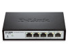
... change back to legacy devices which do not support IEEE 802.3az, D-Link Green Technologies can save energy without compromising any performance. DGS-1100-05 5-Port 10/100/1000Mpbs EasySmart Switch Front Panel Figure 1- DGS-1100-05 Front Panel Power LED: The Power LED lights up when the Switch is running at 10/100M. Reset: By pressing the Reset button...
... change back to legacy devices which do not support IEEE 802.3az, D-Link Green Technologies can save energy without compromising any performance. DGS-1100-05 5-Port 10/100/1000Mpbs EasySmart Switch Front Panel Figure 1- DGS-1100-05 Front Panel Power LED: The Power LED lights up when the Switch is running at 10/100M. Reset: By pressing the Reset button...
Manual
Page 7
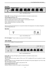
...Light off : Indicates the power budget is either sending or receiving data to a power source. DGS-1100-08P 8-Port 10/100/1000Mpbs PoE EasySmart Switch Front Panel Figure 5 - Light off : No link. Blinking: Indicates that the port is where to the default configuration and all changes will be... powered for 5 seconds the Switch will blink 2 minutes. DGS-1100-08 Front Panel Power LED: The Power LED ...
...Light off : Indicates the power budget is either sending or receiving data to a power source. DGS-1100-08P 8-Port 10/100/1000Mpbs PoE EasySmart Switch Front Panel Figure 5 - Light off : No link. Blinking: Indicates that the port is where to the default configuration and all changes will be... powered for 5 seconds the Switch will blink 2 minutes. DGS-1100-08 Front Panel Power LED: The Power LED ...
Manual
Page 8
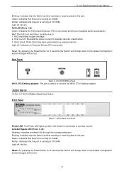
...circuit: Short circuit has been performed on a powered device Light off : No link. DGS-1100-08P Rear Panel 48V/1.57A Desktop adapter: The port is connected to a power source. Blinking: Indicates that the Switch is either sending or receiving data to the port. Reset: By pressing the Reset... button for 5 seconds the Switch will change back to the default configuration and all changes will be lost . 4 DGS-1100-16 16-Port 10/100/1000Mpbs EasySmart Switch Front Panel Figure 7 - Light off : Indicates no Powered Device (PD) connected....
...circuit: Short circuit has been performed on a powered device Light off : No link. DGS-1100-08P Rear Panel 48V/1.57A Desktop adapter: The port is connected to a power source. Blinking: Indicates that the Switch is either sending or receiving data to the port. Reset: By pressing the Reset... button for 5 seconds the Switch will change back to the default configuration and all changes will be lost . 4 DGS-1100-16 16-Port 10/100/1000Mpbs EasySmart Switch Front Panel Figure 7 - Light off : Indicates no Powered Device (PD) connected....

Manual
Page 9
... receiving data to connect the AC power cord. DGS-1100-24 24-Port 10/100/1000Mpbs EasySmart Switch Front Panel Figure 9 - Rear Panel D-Link EasySmart Switch User Manual Figure 8- Link/Act/Speed LED (Ports 1-24): Flashing: Indicates a network link through the corresponding port. All previous changes will be lost. Light off: No link. DGS-1100-24 Front Panel Power LED: The Power...
... receiving data to connect the AC power cord. DGS-1100-24 24-Port 10/100/1000Mpbs EasySmart Switch Front Panel Figure 9 - Rear Panel D-Link EasySmart Switch User Manual Figure 8- Link/Act/Speed LED (Ports 1-24): Flashing: Indicates a network link through the corresponding port. All previous changes will be lost. Light off: No link. DGS-1100-24 Front Panel Power LED: The Power...

Manual
Page 10
... attached on the bottom at each corner of DGS-1100-16/24 One D-Link EasySmart Switch One AC power cord Four rubber feet Screws and two mounting brackets One accessory kit for replacement. Packing contents of DGS-1100-05/08 One D-Link EasySmart Switch One AC Power Adapter Four rubber feet One... accessory kit for wall-mount installation One ground screw that screw on the D-Link EasySmart Switch One Multi-lingual Getting Started Guide One CD with...
... attached on the bottom at each corner of DGS-1100-16/24 One D-Link EasySmart Switch One AC power cord Four rubber feet Screws and two mounting brackets One accessory kit for replacement. Packing contents of DGS-1100-05/08 One D-Link EasySmart Switch One AC Power Adapter Four rubber feet One... accessory kit for wall-mount installation One ground screw that screw on the D-Link EasySmart Switch One Multi-lingual Getting Started Guide One CD with...

Manual
Page 11
... should be placed in a wiring closet with the maximum ambient temperature (Tma) specified by the manufacturer. 7 Figure 12 - D-Link EasySmart Switch User Manual Figure 11 - To install, attach the mounting brackets to the switch's side panels (one on each side) and secure them with the equipment rack to the... Switch Then, use the screws provided with the screws provided (please note that these brackets are not designed for palm size switches). Attach the mounting brackets to...
... should be placed in a wiring closet with the maximum ambient temperature (Tma) specified by the manufacturer. 7 Figure 12 - D-Link EasySmart Switch User Manual Figure 11 - To install, attach the mounting brackets to the switch's side panels (one on each side) and secure them with the equipment rack to the... Switch Then, use the screws provided with the screws provided (please note that these brackets are not designed for palm size switches). Attach the mounting brackets to...

Manual
Page 12
... be used when addressing this purpose. Hook the mounting holes of the equipment is not achieved due to uneven mechanical loading. D-Link EasySmart Switch User Manual B) Reduced Air Flow - Installation of the switch back on the screws. Mounting on a wall. Particular attention should be mounted on a wood wall Step 1: Drive the T3 x 15L...
... be used when addressing this purpose. Hook the mounting holes of the equipment is not achieved due to uneven mechanical loading. D-Link EasySmart Switch User Manual B) Reduced Air Flow - Installation of the switch back on the screws. Mounting on a wall. Particular attention should be mounted on a wood wall Step 1: Drive the T3 x 15L...

Manual
Page 13
... the Switch This section describes how to connect the EasySmart Switch to local and national installation requirements. You must complete this procedure before powering your switch. Figure 16 -Ground cable, screw and #8 terminal lug rings 9 D-Link EasySmart Switch User Manual Figure 15 -Plugging the switch into the...protective ground: Step 1: Verify if the system power is recommended. Commercially available 6 AWG wire is off. The length of the switch to proper grounding facilities. A screwdriver (not included in . Step 5: Attach the terminal lug ring at the ground ...
... the Switch This section describes how to connect the EasySmart Switch to local and national installation requirements. You must complete this procedure before powering your switch. Figure 16 -Ground cable, screw and #8 terminal lug rings 9 D-Link EasySmart Switch User Manual Figure 15 -Plugging the switch into the...protective ground: Step 1: Verify if the system power is recommended. Commercially available 6 AWG wire is off. The length of the switch to proper grounding facilities. A screwdriver (not included in . Step 5: Attach the terminal lug ring at the ground ...

Manual
Page 14
...by using the SmartConsole Utility. Using Web-based Management After a successful physical installation, you want to begin the web configuration of D-Link EasySmart Switch. Supported Web Browsers The embedded Web-based Management currently supports the following web browsers: Internet Explorer 6 or later version Netscape 8 .... The PC's IP address should have an IP address in the same range as the switch. The PC should be in the same range as the switch. D-Link EasySmart Switch User Manual 3 Getting Started This chapter introduces the management interface of your PC and it ...
...by using the SmartConsole Utility. Using Web-based Management After a successful physical installation, you want to begin the web configuration of D-Link EasySmart Switch. Supported Web Browsers The embedded Web-based Management currently supports the following web browsers: Internet Explorer 6 or later version Netscape 8 .... The PC's IP address should have an IP address in the same range as the switch. The PC should be in the same range as the switch. D-Link EasySmart Switch User Manual 3 Getting Started This chapter introduces the management interface of your PC and it ...

Manual
Page 15
...IP address in the same subnet as it appears in the Monitor List. Open the SmartConsole Utility and double-click the switch as the switch. D-Link EasySmart Switch User Manual Figure 17 -Connected Ethernet cable Login Web-based Management In order to login and configure the...gateway of 0.0.0.0. Figure 18 -Enter the IP address 10.90.90.90 in the web browser NOTE: The switch's factory default IP address is only for discovering D-Link Smart Switches and EasySmart Switches within the same L2 network segment connected to launch the Web-based Management, you may either click the Web ...
...IP address in the same subnet as it appears in the Monitor List. Open the SmartConsole Utility and double-click the switch as the switch. D-Link EasySmart Switch User Manual Figure 17 -Connected Ethernet cable Login Web-based Management In order to login and configure the...gateway of 0.0.0.0. Figure 18 -Enter the IP address 10.90.90.90 in the web browser NOTE: The switch's factory default IP address is only for discovering D-Link Smart Switches and EasySmart Switches within the same L2 network segment connected to launch the Web-based Management, you may either click the Web ...

Manual
Page 16
...the SmartConsole Utility. 6. From the Start menu on the installation CD. 1. Connect the Smart Switch to the same L2 network segment of your CD-Rom/DVD-Rom Drive. 2. D-Link EasySmart Switch User Manual NOTE: Please be sure to uninstall any existing SmartConsole Utility from your PC and ...use the SmartConsole Utility to discover the Smart Switches. Connect the Smart Switch to the same L2 network segment of SmartConsole's functions...
...the SmartConsole Utility. 6. From the Start menu on the installation CD. 1. Connect the Smart Switch to the same L2 network segment of your CD-Rom/DVD-Rom Drive. 2. D-Link EasySmart Switch User Manual NOTE: Please be sure to uninstall any existing SmartConsole Utility from your PC and ...use the SmartConsole Utility to discover the Smart Switches. Connect the Smart Switch to the same L2 network segment of SmartConsole's functions...

Manual
Page 17
... of the PC, collect traps and log messages, and quick access to launch the Utility Settings window. D-Link EasySmart Switch User Manual 4 SmartConsole Utility The D-Link SmartConsole Utility allows the administrator to quickly discover all D-Link Smart Switches and EasySmart Switches which were selected as the main body, and SmartConsole Settings at the left . Utility Group Interval establishes...
... of the PC, collect traps and log messages, and quick access to launch the Utility Settings window. D-Link EasySmart Switch User Manual 4 SmartConsole Utility The D-Link SmartConsole Utility allows the administrator to quickly discover all D-Link Smart Switches and EasySmart Switches which were selected as the main body, and SmartConsole Settings at the left . Utility Group Interval establishes...

Manual
Page 18
... Log to show the events of this trap message. Click View Trap to clear all entries. SmartConsole Trap The trap icon in the Switch or the switches will change while receiving new trap messages. Click View Log to exit Figure 53 - Date/Time indicates when the message was received, .../Time indicates when the trap message was received 14 Log Click this icon to launch the Trap window. Please see below for detailed description. D-Link EasySmart Switch User Manual NOTE: If the Group Interval is set to launch the Log window. SmartConsole Log Trap Click this icon to 0, IGMP Snooping must...
... Log to show the events of this trap message. Click View Trap to clear all entries. SmartConsole Trap The trap icon in the Switch or the switches will change while receiving new trap messages. Click View Log to exit Figure 53 - Date/Time indicates when the message was received, .../Time indicates when the trap message was received 14 Log Click this icon to launch the Trap window. Please see below for detailed description. D-Link EasySmart Switch User Manual NOTE: If the Group Interval is set to launch the Log window. SmartConsole Log Trap Click this icon to 0, IGMP Snooping must...

Manual
Page 19
... the Device List. Monitor List By clicking on this icon to launch the Device Settings window. Here you will see below options: D-Link EasySmart Switch User Manual Figure 24- SmartConsole Monitor List Monitor Save: Records the setting of the Device List in the SmartConsole Utility has five icons: Device Settings ...
... the Device List. Monitor List By clicking on this icon to launch the Device Settings window. Here you will see below options: D-Link EasySmart Switch User Manual Figure 24- SmartConsole Monitor List Monitor Save: Records the setting of the Device List in the SmartConsole Utility has five icons: Device Settings ...

Manual
Page 20
SmartConsole Device Settings NOTE: The EasySmart Switch automatically sends out discovery packets to configure the Group Interval setting. Specify the Firmware Path (or Browse for any reason. 16 Password Manager Select a switch from the Device List. Here you are going to launch the ...upgrade fails or cannot be completed for one or many switches of device, and then click Upgrade. SmartConsole Password Manager Firmware Upgrade Select one ) that you can enter a new password and confirm it. D-Link EasySmart Switch User Manual To apply the configuration, insert the correct...
SmartConsole Device Settings NOTE: The EasySmart Switch automatically sends out discovery packets to configure the Group Interval setting. Specify the Firmware Path (or Browse for any reason. 16 Password Manager Select a switch from the Device List. Here you are going to launch the ...upgrade fails or cannot be completed for one or many switches of device, and then click Upgrade. SmartConsole Password Manager Firmware Upgrade Select one ) that you can enter a new password and confirm it. D-Link EasySmart Switch User Manual To apply the configuration, insert the correct...

Manual
Page 21
D-Link EasySmart Switch User Manual Figure 28 -Firmware Upgrade DHCP Refresh: If a DHCP-client enabled switch in the device list. Enter the correct Device Password and then click OK. Add (+), Delete (-) and Discover the device Click the Discovery button to add a ... click the - Click the + and insert a device IP address to display all the Web Smart and EasySmart switches located in the same domain with the management PC. SmartConsole Add device 17 Here you can configure the Switch through the Web-based Management utility. Click this icon to remove it means the device did...
D-Link EasySmart Switch User Manual Figure 28 -Firmware Upgrade DHCP Refresh: If a DHCP-client enabled switch in the device list. Enter the correct Device Password and then click OK. Add (+), Delete (-) and Discover the device Click the Discovery button to add a ... click the - Click the + and insert a device IP address to display all the Web Smart and EasySmart switches located in the same domain with the management PC. SmartConsole Add device 17 Here you can configure the Switch through the Web-based Management utility. Click this icon to remove it means the device did...

Manual
Page 22
... Specify if the device gets the IP address from a DHCP server. SmartConsole Device List Definitions of this device is not available for EasySmart switches. IP Address: Displays the current IP addresses of the device. Trap IP: Displays the IP address of this device. SNMP: Displays ... devices. NOTE: If the devices are marked red in seconds). Figure 32- D-Link EasySmart Switch User Manual Figure 6- SmartConsole Delete device Device List This list displays all discovered Web Smart and EasySmart switches on the network. Please check if the power or the cable of host where the...
... Specify if the device gets the IP address from a DHCP server. SmartConsole Device List Definitions of this device is not available for EasySmart switches. IP Address: Displays the current IP addresses of the device. Trap IP: Displays the IP address of this device. SNMP: Displays ... devices. NOTE: If the devices are marked red in seconds). Figure 32- D-Link EasySmart Switch User Manual Figure 6- SmartConsole Delete device Device List This list displays all discovered Web Smart and EasySmart switches on the network. Please check if the power or the cable of host where the...

