Product Manual
Page 4
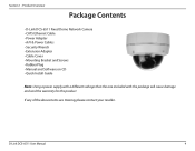
Product Overview PPraocdkaugcteOCvoenrtveinetws • D-Link DCS-6511 Fixed Dome Network Camera • CAT5 Ethernet Cable • Power Adapter • A/V & Power Cables • Security Wrench • Extension Adapter • Cable Cover • Mounting Bracket and Screws • ... Guide Note: Using a power supply with a different voltage than the one included with the package will cause damage and void the warranty for this product. D-Link DCS-6511 User Manual 4 If any of the above items are missing, please contact your reseller. Section 1 -
Product Overview PPraocdkaugcteOCvoenrtveinetws • D-Link DCS-6511 Fixed Dome Network Camera • CAT5 Ethernet Cable • Power Adapter • A/V & Power Cables • Security Wrench • Extension Adapter • Cable Cover • Mounting Bracket and Screws • ... Guide Note: Using a power supply with a different voltage than the one included with the package will cause damage and void the warranty for this product. D-Link DCS-6511 User Manual 4 If any of the above items are missing, please contact your reseller. Section 1 -
Product Manual
Page 5
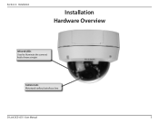
Installation Installation Hardware Overview Infrared LEDs Used to illuminate the camera's field of view at night Camera Lens Motorized varifocal autofocus lens D-Link DCS-6511 User Manual 5 Section 2 -
Installation Installation Hardware Overview Infrared LEDs Used to illuminate the camera's field of view at night Camera Lens Motorized varifocal autofocus lens D-Link DCS-6511 User Manual 5 Section 2 -
Product Manual
Page 6
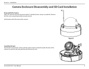
Lift the dome off of the base of the camera. Install the SD Card Push the SD card into the slot. Figure A. Installation Camera Enclosure Disassembly and SD Card Installation Disassemble the Camera Open the camera enclosure by removing the 3 standard screws using the provided security wrench. Remove the 4th screw using a screwdriver. To eject the SD card, push the SD card into the camera with the gold contacts oriented towards the base of the camera. D-Link DCS-6511 User Manual 6 Section 2 -
Lift the dome off of the base of the camera. Install the SD Card Push the SD card into the slot. Figure A. Installation Camera Enclosure Disassembly and SD Card Installation Disassemble the Camera Open the camera enclosure by removing the 3 standard screws using the provided security wrench. Remove the 4th screw using a screwdriver. To eject the SD card, push the SD card into the camera with the gold contacts oriented towards the base of the camera. D-Link DCS-6511 User Manual 6 Section 2 -
Product Manual
Page 7
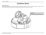
Section 2 - Press and hold the reset button for approximately 10 seconds to factory default settings D-Link DCS-6511 User Manual 7 Reset Button Resets camera to reset the camera. Installation Hardware Reset Resetting the Camera If the camera is malfunctioning, you may use the hardware reset button located on the bottom of the camera apparatus to reset the camera to factory default settings.
Section 2 - Press and hold the reset button for approximately 10 seconds to factory default settings D-Link DCS-6511 User Manual 7 Reset Button Resets camera to reset the camera. Installation Hardware Reset Resetting the Camera If the camera is malfunctioning, you may use the hardware reset button located on the bottom of the camera apparatus to reset the camera to factory default settings.
Product Manual
Page 8
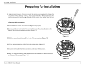
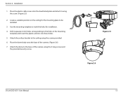
..., when using a screwdriver. (Figure 1.1) 3. Changing Cable Orientation: 1. Lift the camera bracket up and off from the connectors at the base of the camera. (Figure 1.4) Figure 1.2 D-Link DCS-6511 User Manual 8 Installation Preparing for Installation A. Loosen, but do not remove, the two screws that secure the camera bracket to the base of the enclosure using the Surface...
..., when using a screwdriver. (Figure 1.1) 3. Changing Cable Orientation: 1. Lift the camera bracket up and off from the connectors at the base of the camera. (Figure 1.4) Figure 1.2 D-Link DCS-6511 User Manual 8 Installation Preparing for Installation A. Loosen, but do not remove, the two screws that secure the camera bracket to the base of the enclosure using the Surface...
Product Manual
Page 9
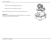
Section 2 - Replace the chrome nut and tighten it into place B. Replace the dome enclosure over the IP camera and tighten the 4 screws. Safety Notice: Installation and servicing should be done by certified technicians so as to conform to all local codes and prevent voiding your warranty. Replace the chrome plug and tighten it into place. 8. Figure 1.3 D-Link DCS-6511 User Manual 9 Installation 7.
Section 2 - Replace the chrome nut and tighten it into place B. Replace the dome enclosure over the IP camera and tighten the 4 screws. Safety Notice: Installation and servicing should be done by certified technicians so as to conform to all local codes and prevent voiding your warranty. Replace the chrome plug and tighten it into place. 8. Figure 1.3 D-Link DCS-6511 User Manual 9 Installation 7.
Product Manual
Page 10
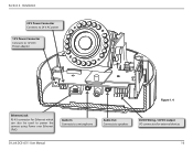
Section 2 - Installation 24 V Power Connector Connects to 24 V AC power 12 V Power Connector Connects to 12 V DC Power adapter Figure 1.4 Ethernet Jack RJ-45 connector for Ethernet which can also be used to power the camera using Power over Ethernet (PoE) Audio In Connects to a microphone Audio Out Connects to speakers DI/DO Wiring, 12V DC output I/O connectors for external devices D-Link DCS-6511 User Manual 10
Section 2 - Installation 24 V Power Connector Connects to 24 V AC power 12 V Power Connector Connects to 12 V DC Power adapter Figure 1.4 Ethernet Jack RJ-45 connector for Ethernet which can also be used to power the camera using Power over Ethernet (PoE) Audio In Connects to a microphone Audio Out Connects to speakers DI/DO Wiring, 12V DC output I/O connectors for external devices D-Link DCS-6511 User Manual 10
Product Manual
Page 11
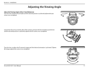
Installation Adjusting the Viewing Angle Adjust the Viewing Angle of the camera, and turn the lens module up and down until the desired orientation is achieved; tighten the tilt screws once completed. Turn the lens to adjust the IP camera's image until the desired position is achieved; Tighten the image adjustment screw once completed. Loosen the tilt screws on both sides of the 3-Axis Mechanism Turn the lens module left and right until the desired position is achieved. D-Link DCS-6511 User Manual 11 tighten the pan screw once completed. Section 2 -
Installation Adjusting the Viewing Angle Adjust the Viewing Angle of the camera, and turn the lens module up and down until the desired orientation is achieved; tighten the tilt screws once completed. Turn the lens to adjust the IP camera's image until the desired position is achieved; Tighten the image adjustment screw once completed. Loosen the tilt screws on both sides of the 3-Axis Mechanism Turn the lens module left and right until the desired position is achieved. D-Link DCS-6511 User Manual 11 tighten the pan screw once completed. Section 2 -
Product Manual
Page 12
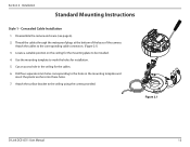
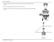
... to mark the holes for the mounting plate to the holes in the ceiling for the cables. 6. Disassemble the camera enclosure (see page 6). 2. Locate a suitable position on the ceiling for installation. 5. Figure 2.1 D-Link DCS-6511 User Manual 12 Cut an access hole in the mounting template and insert the plastic anchors into these holes...
... to mark the holes for the mounting plate to the holes in the ceiling for the cables. 6. Disassemble the camera enclosure (see page 6). 2. Locate a suitable position on the ceiling for installation. 5. Figure 2.1 D-Link DCS-6511 User Manual 12 Cut an access hole in the mounting template and insert the plastic anchors into these holes...
Product Manual
Page 13
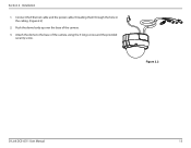
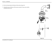
Connect the Ethernet cable and the power cable, threading them through the hole in the ceiling. (Figure 2.2) 2. Push the dome body up over the base of the camera using the 3 long screws and the provided security screw. Figure 2.2 D-Link DCS-6511 User Manual 13 Section 2 - Attach the dome to the base of the camera. 3. Installation 1.
Connect the Ethernet cable and the power cable, threading them through the hole in the ceiling. (Figure 2.2) 2. Push the dome body up over the base of the camera using the 3 long screws and the provided security screw. Figure 2.2 D-Link DCS-6511 User Manual 13 Section 2 - Attach the dome to the base of the camera. 3. Installation 1.
Product Manual
Page 14
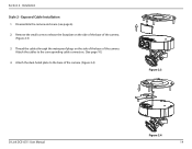
Installation Style 2 - Thread the cables through the waterproof plugs on the side of the base of the camera. (Figure 2.3) 3. Remove the small screw to release the faceplate on the side of the base of the camera. (Figure 2.4) Figure 2.3 D-Link DCS-6511 User Manual Figure 2.4 14 Attach the cables to the base of the camera. Attach the dual-holed plate to the corresponding cable connectors. (See page 10.) 4. Section 2 - Disassemble the camera enclosure (see page 6). 2. Exposed Cable Installation 1.
Installation Style 2 - Thread the cables through the waterproof plugs on the side of the base of the camera. (Figure 2.3) 3. Remove the small screw to release the faceplate on the side of the base of the camera. (Figure 2.4) Figure 2.3 D-Link DCS-6511 User Manual Figure 2.4 14 Attach the cables to the base of the camera. Attach the dual-holed plate to the corresponding cable connectors. (See page 10.) 4. Section 2 - Disassemble the camera enclosure (see page 6). 2. Exposed Cable Installation 1.
Product Manual
Page 15
Drill 4 separate 6 mm holes corresponding to the base of the camera. (Figure 2.6) 7. Figure 2.5 Figure 2.6 D-Link DCS-6511 User Manual 15 Attach the dome to the holes in the mounting template and insert the plastic anchors into these holes. 5. Place the plastic cable ... to be installed. 3. Installation 1. Attach the surface bracket to the ceiling using the screw. (Figure 2.5) 2. Section 2 - Place the dome body onto the base of the camera using the 3 long screws and the provided security screw.
Drill 4 separate 6 mm holes corresponding to the base of the camera. (Figure 2.6) 7. Figure 2.5 Figure 2.6 D-Link DCS-6511 User Manual 15 Attach the dome to the holes in the mounting template and insert the plastic anchors into these holes. 5. Place the plastic cable ... to be installed. 3. Installation 1. Attach the surface bracket to the ceiling using the screw. (Figure 2.5) 2. Section 2 - Place the dome body onto the base of the camera using the 3 long screws and the provided security screw.
Product Manual
Page 17
Section 2 - Figure 3.3 D-Link DCS-6511 User Manual Figure 3.4 17 Attach the dome to the base of the camera. (Figure 3.3) 11. Connect the Ethernet cable and the power cable and thread them through the pendant bracket. 10. Place the dome body onto the base of the camera using the 3 long screws and the provided security screw. Installation 9.
Section 2 - Figure 3.3 D-Link DCS-6511 User Manual Figure 3.4 17 Attach the dome to the base of the camera. (Figure 3.3) 11. Connect the Ethernet cable and the power cable and thread them through the pendant bracket. 10. Place the dome body onto the base of the camera using the 3 long screws and the provided security screw. Installation 9.
Product Manual
Page 19
Bent Bracket Dome Camera Figure 4.3 D-Link DCS-6511 User Manual Figure 4.4 19 Installation 10. Section 2 - Place the dome body onto the base of the camera using the 3 long screws and the provided security screw. Attach the dome to the base of the camera. (Figure 4.3) 11.
Bent Bracket Dome Camera Figure 4.3 D-Link DCS-6511 User Manual Figure 4.4 19 Installation 10. Section 2 - Place the dome body onto the base of the camera using the 3 long screws and the provided security screw. Attach the dome to the base of the camera. (Figure 4.3) 11.
Product Manual
Page 20
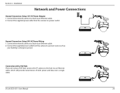
.... Connect the supplied power cable from the camera to a hub via an Ethernet cable. 2. Connection with a PoE Hub If you are using a PoE hub, connect the IP camera to a power source such as your building's emergency power. D-Link DCS-6511 User Manual 20 General Connection Using 24 V... AC Power Wiring 1. Connect the supplied power cable from the camera to the hub via an Ethernet cable, which ...
.... Connect the supplied power cable from the camera to a hub via an Ethernet cable. 2. Connection with a PoE Hub If you are using a PoE hub, connect the IP camera to a power source such as your building's emergency power. D-Link DCS-6511 User Manual 20 General Connection Using 24 V... AC Power Wiring 1. Connect the supplied power cable from the camera to the hub via an Ethernet cable, which ...
Product Manual
Page 24
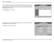
Click the Wizard button to the next page. If your network does not use a DHCP server, the network camera's default static IP address 192.168.0.20 will appear and display the MAC address and IP address of your network, a valid IP Address will be displayed. Enter the Admin ID and password. When logging in for the first time, the default Admin ID is admin with the password left blank. Configuration The Setup Wizard will be displayed. D-Link DCS-6511 User Manual 24 Click Next, to proceed to continue. Section 3 - If you have a DHCP server on your camera(s).
Click the Wizard button to the next page. If your network does not use a DHCP server, the network camera's default static IP address 192.168.0.20 will appear and display the MAC address and IP address of your network, a valid IP Address will be displayed. Enter the Admin ID and password. When logging in for the first time, the default Admin ID is admin with the password left blank. Configuration The Setup Wizard will be displayed. D-Link DCS-6511 User Manual 24 Click Next, to proceed to continue. Section 3 - If you have a DHCP server on your camera(s).

Product Manual
Page 25
Take a moment to the next page. Configuration Select DHCP if your settings and click Restart. Click Next, to proceed to confirm your camera obtains an IP address automatically when it is started. D-Link DCS-6511 User Manual 25 Select Static IP if the camera will use the same IP address each time it boots up. Section 3 -
Take a moment to the next page. Configuration Select DHCP if your settings and click Restart. Click Next, to proceed to confirm your camera obtains an IP address automatically when it is started. D-Link DCS-6511 User Manual 25 Select Static IP if the camera will use the same IP address each time it boots up. Section 3 -
Product Manual
Page 26
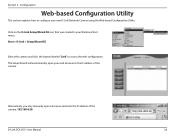
... configure your Windows Start menu. Alternatively, you may manually open your web browser to the IP address of the camera: 192.168.0.20 D-Link DCS-6511 User Manual 26 Section 3 - Configuration Web-based Configuration Utility This section explains how to access the web configuration. The Setup Wizard will automatically open a browser ...
... configure your Windows Start menu. Alternatively, you may manually open your web browser to the IP address of the camera: 192.168.0.20 D-Link DCS-6511 User Manual 26 Section 3 - Configuration Web-based Configuration Utility This section explains how to access the web configuration. The Setup Wizard will automatically open a browser ...
Product Manual
Page 27
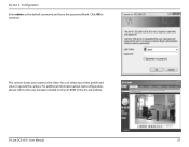
You can select your camera's live video. For additional information about web configuration, please refer to continue. D-Link DCS-6511 User Manual 27 Configuration Enter admin as the default username and leave the password blank. This section shows your video profile and view or operate the camera. Section 3 - Click OK to the user manual included on the CD-ROM or the D-Link website.
You can select your camera's live video. For additional information about web configuration, please refer to continue. D-Link DCS-6511 User Manual 27 Configuration Enter admin as the default username and leave the password blank. This section shows your video profile and view or operate the camera. Section 3 - Click OK to the user manual included on the CD-ROM or the D-Link website.
Product Manual
Page 30
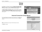
... to choose. Note: Select DHCP if you may click Manual Internet Connection Setup to manually configure your Network Camera and skip to continue. D-Link DCS-6511 User Manual 30 Configuration Setup Wizard To configure your Network Camera's motion detection settings, click Motion Detection Setup Wizard. If you through a step-by-step process to configure your... wizard, click Manual Motion Detection Setup and skip to the internet. Internet Connection Setup Wizard This wizard will guide you want to enter your new D-Link Camera and connect the camera to page 27.
... to choose. Note: Select DHCP if you may click Manual Internet Connection Setup to manually configure your Network Camera and skip to continue. D-Link DCS-6511 User Manual 30 Configuration Setup Wizard To configure your Network Camera's motion detection settings, click Motion Detection Setup Wizard. If you through a step-by-step process to configure your... wizard, click Manual Motion Detection Setup and skip to the internet. Internet Connection Setup Wizard This wizard will guide you want to enter your new D-Link Camera and connect the camera to page 27.


