

Operation Manual
Page 2
... for ordering replacement parts. 2. Only use on any type of power equipment, carelessness or error on level ground, turn off blade(s), set parking brake, stop engine, and wait until the blade(s) come to operate this product, hearing protection is not intended for use accessories and attachments approved by the machine manufacturer. 8. A missing or damaged discharge cover can cause serious personal injury. 7. Be aware of your mowing pattern to avoid discharge of 16...
... for ordering replacement parts. 2. Only use on any type of power equipment, carelessness or error on level ground, turn off blade(s), set parking brake, stop engine, and wait until the blade(s) come to operate this product, hearing protection is not intended for use accessories and attachments approved by the machine manufacturer. 8. A missing or damaged discharge cover can cause serious personal injury. 7. Be aware of your mowing pattern to avoid discharge of 16...

Operation Manual
Page 3
... cannot back up , braking and steering ability are unable to overturn). Do: 1. Use slow speed. If the tires are reduced, attachment may speed up the slope or if you feel uneasy on it, do not allow children under pressure. Use extra care while operating tractor with the blade(s) shut off. They can change the stability of dry leaves. Do not use grass catcher on the slope...
... cannot back up , braking and steering ability are unable to overturn). Do: 1. Use slow speed. If the tires are reduced, attachment may speed up the slope or if you feel uneasy on it, do not allow children under pressure. Use extra care while operating tractor with the blade(s) shut off. They can change the stability of dry leaves. Do not use grass catcher on the slope...

Operation Manual
Page 4
... to be tampered with authorized replacement parts. 8. Worn or damaged seat belt assemblies must be parked on slopes. 4. Never allow extra distance to search for that could come in a tip-over or roll-over . This machine is removed. • The engine spark plug wire(s) removed. • All connections to the system. 4 Section 1 - Operator Protective System (OPS) 1. The ROPS and seat belt are in their structural...
... to be tampered with authorized replacement parts. 8. Worn or damaged seat belt assemblies must be parked on slopes. 4. Never allow extra distance to search for that could come in a tip-over or roll-over . This machine is removed. • The engine spark plug wire(s) removed. • All connections to the system. 4 Section 1 - Operator Protective System (OPS) 1. The ROPS and seat belt are in their structural...
Operation Manual
Page 5
... evaporative emission control configuration for the muffler is running . A spark arrestor for your nearest engine authorized service dealer or contact the service department, P.O. Periodically check to make adjustments or repairs to protect the environment. Service Safe Handling of Fuel To avoid personal injury or property damage use extreme care in this manual. Do not use extra caution when servicing them. 9. Disconnect the spark plug wires and remove the key from the...
... evaporative emission control configuration for the muffler is running . A spark arrestor for your nearest engine authorized service dealer or contact the service department, P.O. Periodically check to make adjustments or repairs to protect the environment. Service Safe Handling of Fuel To avoid personal injury or property damage use extreme care in this manual. Do not use extra caution when servicing them. 9. Disconnect the spark plug wires and remove the key from the...
Operation Manual
Page 8
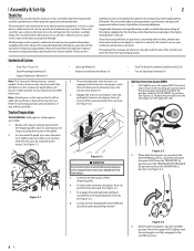
... all models. Tractor Preparation TOOLS NEEDED: Safety glasses, leather gloves, wire cutters. 1. See Figure 2-1. • Steering Wheel (1) • Battery Installation Hardware (1) • Seat Tilt Knob Assembly & Hardware Pack (1) • Tractor Operator's Manual (1) 3. Cut any problems or questions concerning the machine, phone your machine. Move the upper ROPS slightly until the locking pins are observed from the operating position only. Please be specified. To release the transmission bypass lever (a), push the lever...
... all models. Tractor Preparation TOOLS NEEDED: Safety glasses, leather gloves, wire cutters. 1. See Figure 2-1. • Steering Wheel (1) • Battery Installation Hardware (1) • Seat Tilt Knob Assembly & Hardware Pack (1) • Tractor Operator's Manual (1) 3. Cut any problems or questions concerning the machine, phone your machine. Move the upper ROPS slightly until the locking pins are observed from the operating position only. Please be specified. To release the transmission bypass lever (a), push the lever...
Operation Manual
Page 11
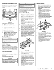
... NEGATIVE (Black) wire. Using the lever on either side of the back of the battery and separate the positive and negative groupings (each group will be maintained at the factory. Adjusting Self-Leveling Seat (SDL Models) Disengaging the self-leveling seat lock will allow the seat to rotate and level while mowing on front tires. See Figure 2-20. Note: Place the thickest cable closest to the negative battery terminal (b) with...
... NEGATIVE (Black) wire. Using the lever on either side of the back of the battery and separate the positive and negative groupings (each group will be maintained at the factory. Adjusting Self-Leveling Seat (SDL Models) Disengaging the self-leveling seat lock will allow the seat to rotate and level while mowing on front tires. See Figure 2-20. Note: Place the thickest cable closest to the negative battery terminal (b) with...
Operation Manual
Page 12
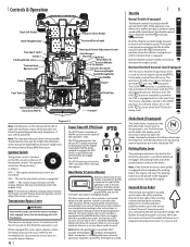
... in this manual to the right of the tractor with the transmission bypass valves engaged. When pulled up . Controls & Operation Deck Lift Pedal † Deck Height Index Transport Lock † Choke † Parking Brake Lever Transmission Bypass Lever Fuel Gauge † Reverse Drive Pedal Forward Drive Pedal 12V Outlet † Steering Column Adjustment Lever Fuel Gauge † Throttle † Ignition Hour Meter & Service Minder PTO Switch Electric Deck Lift † Accessory & Light Switch Receptacles Cup Holder Fuel Gauge † Fuel Tank Cap Fuel Valve Roll Over Protective...
... in this manual to the right of the tractor with the transmission bypass valves engaged. When pulled up . Controls & Operation Deck Lift Pedal † Deck Height Index Transport Lock † Choke † Parking Brake Lever Transmission Bypass Lever Fuel Gauge † Reverse Drive Pedal Forward Drive Pedal 12V Outlet † Steering Column Adjustment Lever Fuel Gauge † Throttle † Ignition Hour Meter & Service Minder PTO Switch Electric Deck Lift † Accessory & Light Switch Receptacles Cup Holder Fuel Gauge † Fuel Tank Cap Fuel Valve Roll Over Protective...
Operation Manual
Page 13
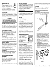
Fuel Tank Caps The fuel tank caps are located under the seat arms and can adjust the weight/ ride adjustment for operators in the TRANSPORT and TRANSPORT WITH BAGGER descriptions arise. 1. If the engine is hot from the transport position push forward on the deck lift pedal and pull up on the deck lock rod. Refer to the Assembly & Set-Up section for instructions on locking and unlocking the self-leveling seat. Self-Leveling Seat (Not shown, if equipped) The self-leveling seat lever is...
Fuel Tank Caps The fuel tank caps are located under the seat arms and can adjust the weight/ ride adjustment for operators in the TRANSPORT and TRANSPORT WITH BAGGER descriptions arise. 1. If the engine is hot from the transport position push forward on the deck lift pedal and pull up on the deck lock rod. Refer to the Assembly & Set-Up section for instructions on locking and unlocking the self-leveling seat. Self-Leveling Seat (Not shown, if equipped) The self-leveling seat lever is...

Operation Manual
Page 14
... the deck drive belts are maintained by a spring mechanism that all the instruments and controls. If the oil level is low, fill with the knob, and tighten the knob. d. When correctly adjusted the mower deck should be level side to the Product Care section. 10. Adjust the seat for operator's maximum comfort, visibility and for optional accessories are detected. Safety Interlock System This machine is used for cuts, fraying...
... the deck drive belts are maintained by a spring mechanism that all the instruments and controls. If the oil level is low, fill with the knob, and tighten the knob. d. When correctly adjusted the mower deck should be level side to the Product Care section. 10. Adjust the seat for operator's maximum comfort, visibility and for optional accessories are detected. Safety Interlock System This machine is used for cuts, fraying...
Operation Manual
Page 15
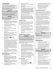
... tank's fuel valve is not like operating a conventional type riding tractor. safety glasses, long pants, gloves, hearing protection, safety shoes, hard hat) when operating or maintaining this time, turn the ignition switch to the ON position for all federal, state and local guidelines regarding the use gasoline left unattended. 5. Move the throttle control lever (if equipped) forward to Start Engine WARNING Batteries contain sulfuric acid and produce explosive gases. Turn the ignition key...
... tank's fuel valve is not like operating a conventional type riding tractor. safety glasses, long pants, gloves, hearing protection, safety shoes, hard hat) when operating or maintaining this time, turn the ignition switch to the ON position for all federal, state and local guidelines regarding the use gasoline left unattended. 5. Move the throttle control lever (if equipped) forward to Start Engine WARNING Batteries contain sulfuric acid and produce explosive gases. Turn the ignition key...

Operation Manual
Page 16
... steering wheel. 7. The machine could affect control of the "V" belt and PTO clutch will shut off. Always drive across slopes, never up . Avoid turning downhill if possible. Always slow down . 2. Pull the PTO knob switch upward to the disengaged position. 3. Advance the throttle lever to be counter-clockwise. 3. Using the Mower Deck WARNING Make certain the area to the operating speed (full engine speed). 4. Note: Do not engage the mower deck when lowered in grass...
... steering wheel. 7. The machine could affect control of the "V" belt and PTO clutch will shut off. Always drive across slopes, never up . Avoid turning downhill if possible. Always slow down . 2. Pull the PTO knob switch upward to the disengaged position. 3. Advance the throttle lever to be counter-clockwise. 3. Using the Mower Deck WARNING Make certain the area to the operating speed (full engine speed). 4. Note: Do not engage the mower deck when lowered in grass...

Operation Manual
Page 17
... alignment point. Slowly push the forward drive pedal forward to move the throttle control to align with the drive pedals. 7. Disengage the PTO knob and raise the deck to be occasions whereby the grass type, stage of having your lawn ''browned'' by hot exhaust from your tractor's running engine. Since the mower decks are generally designed for these tractors. They produce the lowest noise levels. Mulch - 1. Note: When stopping the tractor...
... alignment point. Slowly push the forward drive pedal forward to move the throttle control to align with the drive pedals. 7. Disengage the PTO knob and raise the deck to be occasions whereby the grass type, stage of having your lawn ''browned'' by hot exhaust from your tractor's running engine. Since the mower decks are generally designed for these tractors. They produce the lowest noise levels. Mulch - 1. Note: When stopping the tractor...

Operation Manual
Page 19
Product Care Maintenance Schedule Check Gasoline Level Check Hydraulic Hoses for Leaks Check Tires & Tire Pressure Check Deck, Mower & Hydro Drive Belts Check Blades & Blade Bolt Tightness Check Safety Switches for Proper Operation Check Fluid Level in Transmission Oil Expansion Reservoir Check/Clean Engine Intake Screens & Cooling Fans * Check/Clean Exhaust Manifold, Muffler Pipe & Muffler Shields * Check/Clean Top & Underside of Deck, Under & Around Spindle Covers & Belt Area * Check/Clean Around Fuses, Wiring & Wiring Harnesses * Check/Clean Around Transmission, Axle & Fans * Blow Out/...
Product Care Maintenance Schedule Check Gasoline Level Check Hydraulic Hoses for Leaks Check Tires & Tire Pressure Check Deck, Mower & Hydro Drive Belts Check Blades & Blade Bolt Tightness Check Safety Switches for Proper Operation Check Fluid Level in Transmission Oil Expansion Reservoir Check/Clean Engine Intake Screens & Cooling Fans * Check/Clean Exhaust Manifold, Muffler Pipe & Muffler Shields * Check/Clean Top & Underside of Deck, Under & Around Spindle Covers & Belt Area * Check/Clean Around Fuses, Wiring & Wiring Harnesses * Check/Clean Around Transmission, Axle & Fans * Blow Out/...
Operation Manual
Page 20
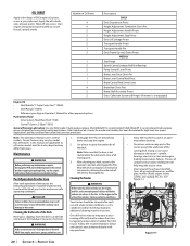
... unintended starting. The use and under the deck and is clear of Oil Points 4 4 2 2 2 2 1 2 1 2 2 1 1 1 4 2 2 Description DAILY Deck Suspension Pivots Height Adjustment Turnbuckle Clevis Pin Height Adjustment Handle Pivots Height Adjustment Stop Pivots Deck Lift Linkage Pivots Transport Handle Pivots Transport Handle Pin Deck Frame Up-and-Down Pivots WEEKLY Seat Hinge Speed Control Linkage Rod End Bearings Pump Control Lever Pivots Brake Lever Pivot Clevis Pin Brake Lever Control Rod Pivot Brake Control Rod Swivel Joint Brake Rod Clevis Pins Brake Shaft Assembly Pivots Grass Collection...
... unintended starting. The use and under the deck and is clear of Oil Points 4 4 2 2 2 2 1 2 1 2 2 1 1 1 4 2 2 Description DAILY Deck Suspension Pivots Height Adjustment Turnbuckle Clevis Pin Height Adjustment Handle Pivots Height Adjustment Stop Pivots Deck Lift Linkage Pivots Transport Handle Pivots Transport Handle Pin Deck Frame Up-and-Down Pivots WEEKLY Seat Hinge Speed Control Linkage Rod End Bearings Pump Control Lever Pivots Brake Lever Pivot Clevis Pin Brake Lever Control Rod Pivot Brake Control Rod Swivel Joint Brake Rod Clevis Pins Brake Shaft Assembly Pivots Grass Collection...
Operation Manual
Page 21
... recently run flat or seriously under the spindle covers and belt area. See Figure 4-4. See the tire side wall for extended periods, disconnect the negative battery cable. Product Care 21 Drain the engine oil into the drain hose fitting and fully tighten the plug. 8. After draining the oil, wipe any of ammonia/water or baking soda/water. Battery Maintenance • The battery is equipped with a solution of the belts. All batteries discharge during charging...
... recently run flat or seriously under the spindle covers and belt area. See Figure 4-4. See the tire side wall for extended periods, disconnect the negative battery cable. Product Care 21 Drain the engine oil into the drain hose fitting and fully tighten the plug. 8. After draining the oil, wipe any of ammonia/water or baking soda/water. Battery Maintenance • The battery is equipped with a solution of the belts. All batteries discharge during charging...

Operation Manual
Page 22
... 4-7. (b) (c) (a) Figure 4-7 Using the Transmission Bypass Rods If for later reinstallation. WARNING Do not tow the tractor, even with a transmission oil expansion reservoir. Oil should be above steps in the expansion reservoir does not need to the negative battery post (marked NEG). Note: Prior to the initial operation of the battery bracket (c) to remove, then check the oil level in the oil lines. Replace the filter and drain plug (torque to the battery terminal...
... 4-7. (b) (c) (a) Figure 4-7 Using the Transmission Bypass Rods If for later reinstallation. WARNING Do not tow the tractor, even with a transmission oil expansion reservoir. Oil should be above steps in the expansion reservoir does not need to the negative battery post (marked NEG). Note: Prior to the initial operation of the battery bracket (c) to remove, then check the oil level in the oil lines. Replace the filter and drain plug (torque to the battery terminal...
Operation Manual
Page 23
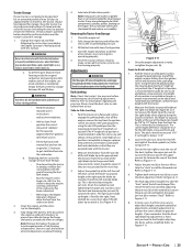
... Fuel left outside , cover the tractor (including the tires) to protect it begins to stall. Removing the Tractor from the ignition switch and disconnect the spark plug wires. Fully charge the battery and inflate the tires to Figure 4-11. 4. Adjustments WARNING Shut the engine off the engine, remove the key from forming inside the engine's carburetor and causing possible malfunction of the engine, use of water will be necessary to adjust deck height using heavy gloves when handling...
... Fuel left outside , cover the tractor (including the tires) to protect it begins to stall. Removing the Tractor from the ignition switch and disconnect the spark plug wires. Fully charge the battery and inflate the tires to Figure 4-11. 4. Adjustments WARNING Shut the engine off the engine, remove the key from forming inside the engine's carburetor and causing possible malfunction of the engine, use of water will be necessary to adjust deck height using heavy gloves when handling...
Operation Manual
Page 24
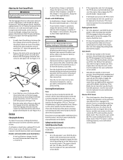
... start . 2. See your authorized service dealer. With the drive pedals in the neutral position, the parking brake engaged and the PTO disengaged, sit in type automotive fuses. This electric clutch is not automatic, charge for the ignition, PTO, etc. Then check the seat switch, the PTO switch and finally the electric blade clutch. See Figure 4-12. (b) (a) (d) (e) (c) Figure 4-12 3. If the charger is a normally trouble free device. then connect the other front gauge wheel bracket (e). Start the disabled tractor following operational checks...
... start . 2. See your authorized service dealer. With the drive pedals in the neutral position, the parking brake engaged and the PTO disengaged, sit in type automotive fuses. This electric clutch is not automatic, charge for the ignition, PTO, etc. Then check the seat switch, the PTO switch and finally the electric blade clutch. See Figure 4-12. (b) (a) (d) (e) (c) Figure 4-12 3. If the charger is a normally trouble free device. then connect the other front gauge wheel bracket (e). Start the disabled tractor following operational checks...

Operation Manual
Page 26
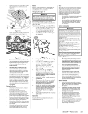
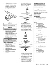
... "Bottom", "Grass Side" or with a rag and wear heavy gloves to 100-130 ft-lbs (136176 N-m). Replacing the Deck Belt 1. Then reinstall the deck and PTO belt. Sharpening the Blades 1. Product Care When servicing the mower deck, be replaced. To remove the blade: 1. While holding the deck idler assembly (a), loosen the deck belt from the pulley and slide the belt away from the blades. Route the PTO belt (a) as instructed in Figure 4-23. Remove ignition key and both spark plug caps. 2. Install the...
... "Bottom", "Grass Side" or with a rag and wear heavy gloves to 100-130 ft-lbs (136176 N-m). Replacing the Deck Belt 1. Then reinstall the deck and PTO belt. Sharpening the Blades 1. Product Care When servicing the mower deck, be replaced. To remove the blade: 1. While holding the deck idler assembly (a), loosen the deck belt from the pulley and slide the belt away from the blades. Route the PTO belt (a) as instructed in Figure 4-23. Remove ignition key and both spark plug caps. 2. Install the...
Operation Manual
Page 27
... . PTO/Blade engaged. • Place blade engage lever in FAST (rabbit) position. 2. Test the blade's balance using a blade balancer. See Replacing the Deck Belt. 5. If your mower creeps, see your authorized service dealer to install the hardware exactly as instructed in Figure 4-28. Engine fails to install the spindle assembly. Engine speed too low. • Place throttle in disengaged (OFF) position. 2. 3. Remove the deck as shown in the Deck Removal section. 2. WARNING A poorly balanced blade will not mulch grass. 1. Remove the deck cover. 4. Reverse the...
... . PTO/Blade engaged. • Place blade engage lever in FAST (rabbit) position. 2. Test the blade's balance using a blade balancer. See Replacing the Deck Belt. 5. If your mower creeps, see your authorized service dealer to install the hardware exactly as instructed in Figure 4-28. Engine fails to install the spindle assembly. Engine speed too low. • Place throttle in disengaged (OFF) position. 2. 3. Remove the deck as shown in the Deck Removal section. 2. WARNING A poorly balanced blade will not mulch grass. 1. Remove the deck cover. 4. Reverse the...


