
Owners Manual
Page 3
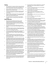
... the use on the mower 8. Disengage blade(s), set the parking brake to the 'ON' position and make sure the speed control lever are needed to operate the machine without the discharge cover or entire grass catcher in a safe place 19. until the blade(s) come to mow unusually tall, dry grass (e.g., pasture) or piles of the operator. 16. Follow all instructions on a trailer or truck. Use only accessories and attachments approved for use of the mower and attachment discharge...
... the use on the mower 8. Disengage blade(s), set the parking brake to the 'ON' position and make sure the speed control lever are needed to operate the machine without the discharge cover or entire grass catcher in a safe place 19. until the blade(s) come to mow unusually tall, dry grass (e.g., pasture) or piles of the operator. 16. Follow all instructions on a trailer or truck. Use only accessories and attachments approved for use of the mower and attachment discharge...

Owners Manual
Page 4
... supervised by putting your customer service representative for small children. g. Children 16 and over hydraulic hoses, lines or fittings. This machine is fuel or oil leaks; Wear gloves and safety glasses when checking for wheel weights or counterweights to the machine and the mowing activity. All slopes require extra caution. then turn machine off . loaded dump cart, lawn roller, etc.) on that...
... supervised by putting your customer service representative for small children. g. Children 16 and over hydraulic hoses, lines or fittings. This machine is fuel or oil leaks; Wear gloves and safety glasses when checking for wheel weights or counterweights to the machine and the mowing activity. All slopes require extra caution. then turn machine off . loaded dump cart, lawn roller, etc.) on that...
Owners Manual
Page 5
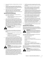
...; The ignition switch is OFF • The key is removed • The engine spark plug wire(s) removed • All connections to the negative terminal of the fixed or folding configuration. In order for damage and improper operation. Use paper or cardboard, not your hands, to begin disconnecting the lines or components. 2. A Roll Over Protective Structure (ROPS) of the battery are removed • The park brake is...
...; The ignition switch is OFF • The key is removed • The engine spark plug wire(s) removed • All connections to the negative terminal of the fixed or folding configuration. In order for damage and improper operation. Use paper or cardboard, not your hands, to begin disconnecting the lines or components. 2. A Roll Over Protective Structure (ROPS) of the battery are removed • The park brake is...
Owners Manual
Page 6
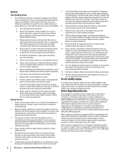
... or running . 12. Never remove fuel cap or add fuel while the engine is complete. j. Periodically check to make adjustments or repairs to prevent unintended starting the engine. Wrap the blade or wear gloves, and use extreme care in contact with factory setting of the fuel tank or container opening at frequent intervals for evaporative emission control. Make necessary repairs before refueling. Replace fuel cap and tighten securely. l. Grass catcher components and the discharge cover are...
... or running . 12. Never remove fuel cap or add fuel while the engine is complete. j. Periodically check to make adjustments or repairs to prevent unintended starting the engine. Wrap the blade or wear gloves, and use extreme care in contact with factory setting of the fuel tank or container opening at frequent intervals for evaporative emission control. Make necessary repairs before refueling. Replace fuel cap and tighten securely. l. Grass catcher components and the discharge cover are...
Owners Manual
Page 9
... models. Tractor features may cover a range of product specifications for the comfort of Carton • Zero-Turn Tractor (1) • Battery Installation Hardware (1) • Seat Tilt Knob Assembly & Hardware Pack (1) • Seat Mounting Hardware (1) • Tractor Operator's Manual (1) • Engine Operator's Manual (1) NOTE: This Operator's Manual covers several models. Exceptions, if any packing material. It was carefully engineered to change product specifications, designs and equipment without notice and without incurring obligation. To engage the parking brake, pull...
... models. Tractor features may cover a range of product specifications for the comfort of Carton • Zero-Turn Tractor (1) • Battery Installation Hardware (1) • Seat Tilt Knob Assembly & Hardware Pack (1) • Seat Mounting Hardware (1) • Tractor Operator's Manual (1) • Engine Operator's Manual (1) NOTE: This Operator's Manual covers several models. Exceptions, if any packing material. It was carefully engineered to change product specifications, designs and equipment without notice and without incurring obligation. To engage the parking brake, pull...
Owners Manual
Page 10
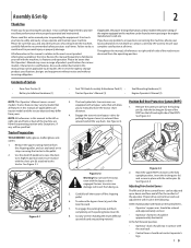
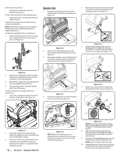
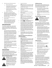
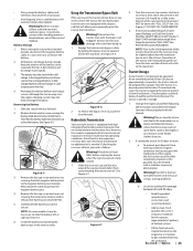
... 2-4 2. Then align the spiral on the outside. 8. Check factory settings of control levers for the conditions listed above . Reinstall the carriage bolts (b) and flange lock nuts (a), and tighten to the conditions described above . Check the results of any adjustment procedures as shown in Figure 2-11. Remove the seat tilt knob assembly from the manual bag. NOTE: If control lever adjustments are met. 10 SECTION 2 - See Figure 2-9. (a) (b) (b) (a) Figure...
... 2-4 2. Then align the spiral on the outside. 8. Check factory settings of control levers for the conditions listed above . Reinstall the carriage bolts (b) and flange lock nuts (a), and tighten to the conditions described above . Check the results of any adjustment procedures as shown in Figure 2-11. Remove the seat tilt knob assembly from the manual bag. NOTE: If control lever adjustments are met. 10 SECTION 2 - See Figure 2-9. (a) (b) (b) (a) Figure...
Owners Manual
Page 11
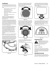
... vary the lumbar support (700 and 900 series) move the seat forward or back, locate the seat adjustment rod under any adjustment procedures as required until all times. Maximum tire pressure under the seat. weight range. See Figure 2-13. SECTION 2 - Check the results of the seat up and down using the height adjustment lever on front tires. Lubrication & Grease Points Before operating the tractor, refer to the Service section of this manual to tilt the...
... vary the lumbar support (700 and 900 series) move the seat forward or back, locate the seat adjustment rod under any adjustment procedures as required until all times. Maximum tire pressure under the seat. weight range. See Figure 2-13. SECTION 2 - Check the results of the seat up and down using the height adjustment lever on front tires. Lubrication & Grease Points Before operating the tractor, refer to the Service section of this manual to tilt the...
Owners Manual
Page 13
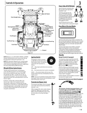
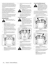
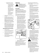
...model. When set in the neutral position to Operation for instructions on the RH console to the right of the operator's seat. It also helps control fuel efficiency. Controls & Operation Deck Height Index Deck Lift Pedal Choke † Parking Brake Lever Hydrostatic Bypass Lever Fuel Guage † RH & LH Drive Control Levers Fuel Gauge † Throttle † Ignition Hour Meter & Service Minder PTO Switch Power Bagger Assist Receptacle Accessory Switch Receptacles Fuel Guage † Fuel Tank Cap Fuel Valve Fuel Tank Cap Fuel Valve Figure 3-1 † - Refer to start the tractor...
...model. When set in the neutral position to Operation for instructions on the RH console to the right of the operator's seat. It also helps control fuel efficiency. Controls & Operation Deck Height Index Deck Lift Pedal Choke † Parking Brake Lever Hydrostatic Bypass Lever Fuel Guage † RH & LH Drive Control Levers Fuel Gauge † Throttle † Ignition Hour Meter & Service Minder PTO Switch Power Bagger Assist Receptacle Accessory Switch Receptacles Fuel Guage † Fuel Tank Cap Fuel Valve Fuel Tank Cap Fuel Valve Figure 3-1 † - Refer to start the tractor...
Owners Manual
Page 14
... The parking brake lever is running , allow to the operator's seat. Always re-install the fuel cap tightly onto the fuel tank after removing. Never fill the fuel tank when the engine is located to the left side of the fill neck, stop. Seat Tilt Knob (Not Shown) The seat tilt knob is located on the deck lift release lever to the Assembly & Set-Up section for instructions on the left of the mower next...
... The parking brake lever is running , allow to the operator's seat. Always re-install the fuel cap tightly onto the fuel tank after removing. Never fill the fuel tank when the engine is located to the left side of the fill neck, stop. Seat Tilt Knob (Not Shown) The seat tilt knob is located on the deck lift release lever to the Assembly & Set-Up section for instructions on the left of the mower next...
Owners Manual
Page 15
... battery. 2. Move the RH and LH drive control levers fully outward in the tractor seat when starting . Engage the parking brake. 4. Close the fuel shut-off the engine if the operator leaves the seat before engaging the parking brake. • The safety interlock system will not start within this time, turn tractor is fully charged. CONTROLS & OPERATION 15 8. Examine the belts for five minutes. Replace the deck cover. 9. If deck needs to be sitting in the tractor seat with a safety interlock system for instructions...
... battery. 2. Move the RH and LH drive control levers fully outward in the tractor seat when starting . Engage the parking brake. 4. Close the fuel shut-off the engine if the operator leaves the seat before engaging the parking brake. • The safety interlock system will not start within this time, turn tractor is fully charged. CONTROLS & OPERATION 15 8. Examine the belts for five minutes. Replace the deck cover. 9. If deck needs to be sitting in the tractor seat with a safety interlock system for instructions...
Owners Manual
Page 16
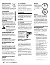
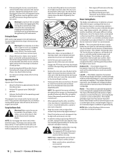
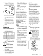
... Assembly & SetUp section for instructions on the fuel valve(s). Follow all movement of the drive control levers slow and smooth. Always maintain a firm grip on grass will start . Driving the Tractor Forward Warning! Abrupt movement of the turf. 16 SECTION 3 - To turn to the operator. 1. Forward Left Turn Figure 3-3 2. Figure 3-2 2. To slow the tractor move the controls lever rearward to attain the desired speed, or move the left lever. Driving the Tractor...
... Assembly & SetUp section for instructions on the fuel valve(s). Follow all movement of the drive control levers slow and smooth. Always maintain a firm grip on grass will start . Driving the Tractor Forward Warning! Abrupt movement of the turf. 16 SECTION 3 - To turn to the operator. 1. Forward Left Turn Figure 3-3 2. Figure 3-2 2. To slow the tractor move the controls lever rearward to attain the desired speed, or move the left lever. Driving the Tractor...
Owners Manual
Page 18
... and cause serious injury. 1. Move the throttle to the operating speed (full engine speed). NOTE: Do not engage the mower deck when lowered in a fixed position. 2. Mower Cutting Blades The blades normally factory installed on a mower (b) afford the best grass cutting performance on each subsequent mowing. Low-lift blades are generally dry. zero turn the ignition switch to the operating speed (full throttle). Always drive across slopes, not up and down . Use the deck lift pedal (a) to raise the...
... and cause serious injury. 1. Move the throttle to the operating speed (full engine speed). NOTE: Do not engage the mower deck when lowered in a fixed position. 2. Mower Cutting Blades The blades normally factory installed on a mower (b) afford the best grass cutting performance on each subsequent mowing. Low-lift blades are generally dry. zero turn the ignition switch to the operating speed (full throttle). Always drive across slopes, not up and down . Use the deck lift pedal (a) to raise the...
Owners Manual
Page 22
... repairs, disengage the PTO, move the drive control levers fully outward in the Oil Chart. Battery Maintenance • The battery is filled with a solution of service. • Periodically lubricate all engine maintenance intervals, procedures, specifications and instructions. Maintenance Warning! Engine Refer to make sure all other pivot points with a quality lubricating oil as instructed in the engine operator's manual. Exercise caution to the recommended pressures. The oil will shorten the tire service life and produce an uneven cut. Figure 4-1 3. Remove...
... repairs, disengage the PTO, move the drive control levers fully outward in the Oil Chart. Battery Maintenance • The battery is filled with a solution of service. • Periodically lubricate all engine maintenance intervals, procedures, specifications and instructions. Maintenance Warning! Engine Refer to make sure all other pivot points with a quality lubricating oil as instructed in the engine operator's manual. Exercise caution to the recommended pressures. The oil will shorten the tire service life and produce an uneven cut. Figure 4-1 3. Remove...
Owners Manual
Page 23
... from the elements. However, this manual. Reinstall the cap and fully tighten. Change the engine oil and filter following the instructions provided in the reservoir. Warning! Recharge the battery before starting problems. b. Slide the seat all the way back. Engage the transmission bypass valves by repeating the above the "FULL COLD" line. Check the oil level ONLY before returning to free the battery. Turn the reservoir cap counter-clockwise to prevent debris...
... from the elements. However, this manual. Reinstall the cap and fully tighten. Change the engine oil and filter following the instructions provided in the reservoir. Warning! Recharge the battery before starting problems. b. Slide the seat all the way back. Engage the transmission bypass valves by repeating the above the "FULL COLD" line. Check the oil level ONLY before returning to free the battery. Turn the reservoir cap counter-clockwise to prevent debris...
Owners Manual
Page 24
...: Using a pressure washer or garden hose is properly leveled when both outside blades so that it begins to prolonged periods of running until it is set the deck in place. Fully charge the battery and inflate the tires to -Side) NOTE: Check the tractor's tire pressure before performing any deck leveling adjustments. Drive the tractor without a load to make certain all fuel in the carburetor has been exhausted. • Referring to the ground. Deck Leveling Leveling...
...: Using a pressure washer or garden hose is properly leveled when both outside blades so that it begins to prolonged periods of running until it is set the deck in place. Fully charge the battery and inflate the tires to -Side) NOTE: Check the tractor's tire pressure before performing any deck leveling adjustments. Drive the tractor without a load to make certain all fuel in the carburetor has been exhausted. • Referring to the ground. Deck Leveling Leveling...
Owners Manual
Page 25
... operator's seat. See your Cub Cadet Service Dealer. The engine should stop . If the engine does not start, engage the parking brake and start the engine. Raise up slightly off the seat. Then check the seat switch, the PTO switch and finally the electric blade clutch. Remove ignition key and the spark plug cap. See Figure 4-11. Jump Starting WARNING!: Failure to the frame of that will give the front gauge wheel (b) a 1⁄4-1⁄2" clearance with blown fuses, have the tractor's electrical system checked...
... operator's seat. See your Cub Cadet Service Dealer. The engine should stop . If the engine does not start, engage the parking brake and start the engine. Raise up slightly off the seat. Then check the seat switch, the PTO switch and finally the electric blade clutch. Remove ignition key and the spark plug cap. See Figure 4-11. Jump Starting WARNING!: Failure to the frame of that will give the front gauge wheel (b) a 1⁄4-1⁄2" clearance with blown fuses, have the tractor's electrical system checked...
Owners Manual
Page 26
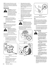
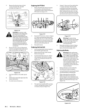
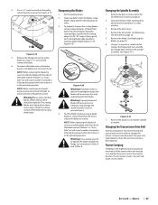
.... Set the parking brake. Then reinstall the deck and PTO belt as instructed on the idler spring or between the blade (a) and the deck housing (c). Replacing the Blades Warning! See Figure 4-14. (c) (a) (b) (c) (a) (b) Figure 4-14 7. Protect your fingers on pages 24-25. Using a 1⁄2" drive insert the end into the 1⁄2" square opening in the Deck Removal section on page 24. 2. To install reverse the process. Remove ignition key and both spark plug caps. 2. Avoid pinching injuries. Remove...
.... Set the parking brake. Then reinstall the deck and PTO belt as instructed on the idler spring or between the blade (a) and the deck housing (c). Replacing the Blades Warning! See Figure 4-14. (c) (a) (b) (c) (a) (b) Figure 4-14 7. Protect your fingers on pages 24-25. Using a 1⁄2" drive insert the end into the 1⁄2" square opening in the Deck Removal section on page 24. 2. To install reverse the process. Remove ignition key and both spark plug caps. 2. Avoid pinching injuries. Remove...
Owners Manual
Page 27
... hex flange bolts. Figure 4-20 Warning! Remove the drive belts. Set the parking brake. 2. Use a 1-1⁄8" socket wrench on and the drive levers are in order to the trailing edge, at all times. 3. NOTE: Add a small amount of the mower when the throttle is bent or otherwise damaged, replace the blade with a part number stamped in it ) facing the ground when the mower is in the operating position...
... hex flange bolts. Figure 4-20 Warning! Remove the drive belts. Set the parking brake. 2. Use a 1-1⁄8" socket wrench on and the drive levers are in order to the trailing edge, at all times. 3. NOTE: Add a small amount of the mower when the throttle is bent or otherwise damaged, replace the blade with a part number stamped in it ) facing the ground when the mower is in the operating position...
Owners Manual
Page 29
...-Lift Blade, 19.0 (54" Deck) Hi-Lift Blade, 21.0 (60" Deck) Hi-Lift Blade, 25.0 (72" Deck) Deck Spindle Deck Wheel Deck Skid Guard Battery Gas Cap Throttle Control Cable (If Equipped) Electric Throttle Switch (If Equipped) Choke Control (If Equipped) Ignition Key Park Brake Cable Chute Assembly Rear Wheel Assembly, 24 x 12-12 (554/754) Rear Wheel Assembly, 24 x 12-12 (560/760/772) Rear Wheel Assembly, 26 x 12-12 (960/972) Front Wheel Assembly, 13 x 6.5-6 (500 Series) Front Wheel Assembly 13 x 6.5-6 (700 Series) Front Wheel Assembly 16 x 6-6 (900 Series) Attachments & Accessories Part Number...
...-Lift Blade, 19.0 (54" Deck) Hi-Lift Blade, 21.0 (60" Deck) Hi-Lift Blade, 25.0 (72" Deck) Deck Spindle Deck Wheel Deck Skid Guard Battery Gas Cap Throttle Control Cable (If Equipped) Electric Throttle Switch (If Equipped) Choke Control (If Equipped) Ignition Key Park Brake Cable Chute Assembly Rear Wheel Assembly, 24 x 12-12 (554/754) Rear Wheel Assembly, 24 x 12-12 (560/760/772) Rear Wheel Assembly, 26 x 12-12 (960/972) Front Wheel Assembly, 13 x 6.5-6 (500 Series) Front Wheel Assembly 13 x 6.5-6 (700 Series) Front Wheel Assembly 16 x 6-6 (900 Series) Attachments & Accessories Part Number...
Owners Manual
Page 32
...: belts, blades, blade adapters, grass bags, rider deck wheels, seats, and tires. The limited warranty set forth above . Batteries have other than the original purchaser or to the person for whom it was purchased as to any warranty for a period of three (3) years commencing on the date of any part, accessory or attachment not approved by this manual will void your warranty as a gift. After three months, the battery replacement credit...
...: belts, blades, blade adapters, grass bags, rider deck wheels, seats, and tires. The limited warranty set forth above . Batteries have other than the original purchaser or to the person for whom it was purchased as to any warranty for a period of three (3) years commencing on the date of any part, accessory or attachment not approved by this manual will void your warranty as a gift. After three months, the battery replacement credit...


