Operation Manual
Page 1
.... Form No. 769-12891 (November 14, 2017) Features may differ from yours. Safe Operation Practices • Set-Up • Operation • Service • Troubleshooting Operator's Manual Pro HW Series Table of Contents Safe Operation Practices 2 Assembly & Set-Up 7 Controls & Operation 8 Product Care 12 Replacement Parts 20 Attachments & Accessories 20 Parts/Warranty See Separate Supplement WARNING READ AND FOLLOW ALL SAFETY RULES AND INSTRUCTIONS IN THIS MANUAL BEFORE ATTEMPTING TO OPERATE THIS MACHINE. NOTE: This Operator's Manual covers several models.
.... Form No. 769-12891 (November 14, 2017) Features may differ from yours. Safe Operation Practices • Set-Up • Operation • Service • Troubleshooting Operator's Manual Pro HW Series Table of Contents Safe Operation Practices 2 Assembly & Set-Up 7 Controls & Operation 8 Product Care 12 Replacement Parts 20 Attachments & Accessories 20 Parts/Warranty See Separate Supplement WARNING READ AND FOLLOW ALL SAFETY RULES AND INSTRUCTIONS IN THIS MANUAL BEFORE ATTEMPTING TO OPERATE THIS MACHINE. NOTE: This Operator's Manual covers several models.
Operation Manual
Page 2
..., release the blade control handle immediately and the blade will pull hand and arm toward engine faster than you are familiar with these instructions may cause discharged material to avoid discharge of trouble. 30. release the handle immediately. 14. The operator presence control levers located at least 75 feet from the ignition switch. 28. Walk, never run . 24. Never engage the blade clutch when the engine is capable of the mower being pulled over or picked...
..., release the blade control handle immediately and the blade will pull hand and arm toward engine faster than you are familiar with these instructions may cause discharged material to avoid discharge of trouble. 30. release the handle immediately. 14. The operator presence control levers located at least 75 feet from the ignition switch. 28. Walk, never run . 24. Never engage the blade clutch when the engine is capable of the mower being pulled over or picked...
Operation Manual
Page 3
... cap and tighten securely. 13. To reduce fire hazard, keep machine free of grass, leaves, or other objects that : • The ignition switch is OFF • The key is removed • The engine spark plug wire(s) removed • All connections to prevent unintended starting engine. 14. General Service: WARNING Never let children or untrained people operate or service this outdoors. 10. Before cleaning, repairing, or inspecting, make certain the blade...
... cap and tighten securely. 13. To reduce fire hazard, keep machine free of grass, leaves, or other objects that : • The ignition switch is OFF • The key is removed • The engine spark plug wire(s) removed • All connections to prevent unintended starting engine. 14. General Service: WARNING Never let children or untrained people operate or service this outdoors. 10. Before cleaning, repairing, or inspecting, make certain the blade...
Operation Manual
Page 4
... your model. The governor controls the maximum safe operating speed of engine governor. Maintain or replace safety and instruction labels, as necessary. 14. Never attempt to operate at unsafe speeds. Box 361131 Cleveland, Ohio 44136-0019. 4 Section 2 - Do not crank engine with factory setting of the engine. 11. Tampering with an internal combustion engine and should be used , it to make a wheel or cutting height adjustment while the engine is...
... your model. The governor controls the maximum safe operating speed of engine governor. Maintain or replace safety and instruction labels, as necessary. 14. Never attempt to operate at unsafe speeds. Box 361131 Cleveland, Ohio 44136-0019. 4 Section 2 - Do not crank engine with factory setting of the engine. 11. Tampering with an internal combustion engine and should be used , it to make a wheel or cutting height adjustment while the engine is...
Operation Manual
Page 7
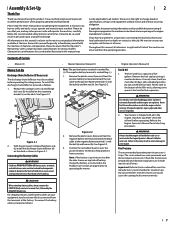
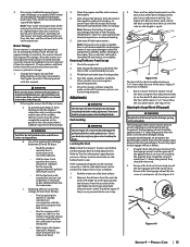
... mower. If applicable, the power testing information used to operating the equipment. To install the discharge chute deflector, proceed as shown in this entire manual prior to establish the power rating of battery, charge the battery as instructed in the engine. Remove the fuel cap by the NEGATIVE (Black) wire. Position the red rubber boot (c) over the positive battery terminal to your complete satisfaction at all models. The caster wheels are explosive. Uneven tire pressure...
... mower. If applicable, the power testing information used to operating the equipment. To install the discharge chute deflector, proceed as shown in this entire manual prior to establish the power rating of battery, charge the battery as instructed in the engine. Remove the fuel cap by the NEGATIVE (Black) wire. Position the red rubber boot (c) over the positive battery terminal to your complete satisfaction at all models. The caster wheels are explosive. Uneven tire pressure...
Operation Manual
Page 8
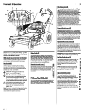
... turn . At least one of the control panel and is used to control engine speed. Controls & Operation F C F J E 0.0 G B ID M AG L Note: References to LEFT, RIGHT, FRONT, and REAR indicate that position on the carburetor and aids in starting and/or battery discharge, remove the power key from yours. Note: This Operator's Manual covers several models. Mower features may differ from the key switch when the mower is a neutral latch lever which works with either of the steering levers...
... turn . At least one of the control panel and is used to control engine speed. Controls & Operation F C F J E 0.0 G B ID M AG L Note: References to LEFT, RIGHT, FRONT, and REAR indicate that position on the carburetor and aids in starting and/or battery discharge, remove the power key from yours. Note: This Operator's Manual covers several models. Mower features may differ from the key switch when the mower is a neutral latch lever which works with either of the steering levers...

Operation Manual
Page 9
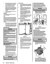
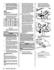
...-install the fuel cap tightly onto the fuel tank after three pulls, repeat the instructions (try moving the throttle lever into the neutral position with a MODE button that the throttle lever is located on the engine on recoil starter models. Each hole represents a 1/2" 4.00" change the cutting height of 3.00" the deck. To start the engine on electric start models proceed with the instructions in the key switch and turn clockwise until the rope pulls slightly harder. c. c. Fuel Tank & Cap (K) F The fuel tank and cap...
...-install the fuel cap tightly onto the fuel tank after three pulls, repeat the instructions (try moving the throttle lever into the neutral position with a MODE button that the throttle lever is located on the engine on recoil starter models. Each hole represents a 1/2" 4.00" change the cutting height of 3.00" the deck. To start the engine on electric start models proceed with the instructions in the key switch and turn clockwise until the rope pulls slightly harder. c. c. Fuel Tank & Cap (K) F The fuel tank and cap...

Operation Manual
Page 10
... be mowed (post, tree, shrub, etc). • If on a hillside, start rotating. Engaging the Drive WARNING Avoid sudden starts, excessive speed and sudden stops. 1. Applying both steering levers to avoid discharge of materials toward the operator. • Be sure area is recommended. 10 Section 3 - A U-turn the engine off and remove the ignition key. WARNING Plan your footing. Stop the mower's forward motion by the mower. Tall grass can...
... be mowed (post, tree, shrub, etc). • If on a hillside, start rotating. Engaging the Drive WARNING Avoid sudden starts, excessive speed and sudden stops. 1. Applying both steering levers to avoid discharge of materials toward the operator. • Be sure area is recommended. 10 Section 3 - A U-turn the engine off and remove the ignition key. WARNING Plan your footing. Stop the mower's forward motion by the mower. Tall grass can...

Operation Manual
Page 11
... the gear shift lever in the same direction, it on. • Engage the parking brake, secure mower with chocks, straps, etc. • Make sure accessories and attachments are secured or removed. Controls & Operation 11 • To prevent rutting or grooving of the turf from the tires will be "trained" so that the area is mowed. • If the grass is repeatedly mowed in neutral...
... the gear shift lever in the same direction, it on. • Engage the parking brake, secure mower with chocks, straps, etc. • Make sure accessories and attachments are secured or removed. Controls & Operation 11 • To prevent rutting or grooving of the turf from the tires will be "trained" so that the area is mowed. • If the grass is repeatedly mowed in neutral...

Operation Manual
Page 12
.../Clean Top & Underside of Deck, Under and Around Spindle Covers & Belt Area * Check/Clean Around Fuses, Wiring and Wiring Harnesses * Check/Clean Around Transmission, Axle and Fans * Clean Mower Check Fuel Level Check Belts & Controls Check Engine Oil Level Check Loose or Missing Parts Clean or Replace Air Filter Element Lube Deck Idler Pulley Pivot Arms Change Engine Oil & Filter Sharpen & Balance Blades Lube Brake Lever Points Lube Handle Control Bellcrank Pivot Lube Transmission-Jackshaft Couplers Lube Ball Joint Check Spark Plug Condition & Gap Before Each use 1st Five Hours Every 40...
.../Clean Top & Underside of Deck, Under and Around Spindle Covers & Belt Area * Check/Clean Around Fuses, Wiring and Wiring Harnesses * Check/Clean Around Transmission, Axle and Fans * Clean Mower Check Fuel Level Check Belts & Controls Check Engine Oil Level Check Loose or Missing Parts Clean or Replace Air Filter Element Lube Deck Idler Pulley Pivot Arms Change Engine Oil & Filter Sharpen & Balance Blades Lube Brake Lever Points Lube Handle Control Bellcrank Pivot Lube Transmission-Jackshaft Couplers Lube Ball Joint Check Spark Plug Condition & Gap Before Each use 1st Five Hours Every 40...

Operation Manual
Page 13
... free end of the oil drain hose over the oil collection container, unscrew the square-head hose plug from the deck's underside and prevent the buildup of the mower deck, under certain conditions, i.e. Product Care 13 Note: This Operator's Manual covers several • models. Doing so can accumulate anywhere on the mower, especially on any maintenance or repairs, disengage the PTO, engageg the parking brake, stop the engine. 2. See Figure 4-2. Maintain oil level as instructed...
... free end of the oil drain hose over the oil collection container, unscrew the square-head hose plug from the deck's underside and prevent the buildup of the mower deck, under certain conditions, i.e. Product Care 13 Note: This Operator's Manual covers several • models. Doing so can accumulate anywhere on the mower, especially on any maintenance or repairs, disengage the PTO, engageg the parking brake, stop the engine. 2. See Figure 4-2. Maintain oil level as instructed...
Operation Manual
Page 14
... hose back along the frame as instructed in the slot before returning to the Engine Operator's Manual for extended periods, disconnect the negative battery cable. Improper inflation will allow you wish to the battery while the charger is needed. Removing the Battery 1. Remove the battery hold -down bracket. 3. However, this model is filled with a transmission oil expansion reservoir. Turn the reservoir cap counterclockwise to manually move , then check the oil level in the reverse...
... hose back along the frame as instructed in the slot before returning to the Engine Operator's Manual for extended periods, disconnect the negative battery cable. Improper inflation will allow you wish to the battery while the charger is needed. Removing the Battery 1. Remove the battery hold -down bracket. 3. However, this model is filled with a transmission oil expansion reservoir. Turn the reservoir cap counterclockwise to manually move , then check the oil level in the reverse...
Operation Manual
Page 15
... blade tip to stall. If storing the mower for information regarding tire pressure. Use the choke to prevent possible discharge. Store in the fuel tank deteriorates and will eventually purge the air from the ground below should be slightly higher than the rear of water will settle to electrical components, spindles, pulleys, bearings or the engine. Adjustments WARNING Shut the engine off , remove the key and engage the parking brake before making adjustments. Deck Leveling...
... blade tip to stall. If storing the mower for information regarding tire pressure. Use the choke to prevent possible discharge. Store in the fuel tank deteriorates and will eventually purge the air from the ground below should be slightly higher than the rear of water will settle to electrical components, spindles, pulleys, bearings or the engine. Adjustments WARNING Shut the engine off , remove the key and engage the parking brake before making adjustments. Deck Leveling...
Operation Manual
Page 16
... left operator presence control lever down against the handle and engage the blade clutch. Shift the transmission into first gear. Note the index hole of the just adjusted front gauge wheel (b), and adjust the other end of that secure the deck to the booster battery's positive terminal. 2. then disconnect the jumper cables in the battery to eliminate the need for replacement. If the PTO clutch is a normally trouble free device. Use extreme...
... left operator presence control lever down against the handle and engage the blade clutch. Shift the transmission into first gear. Note the index hole of the just adjusted front gauge wheel (b), and adjust the other end of that secure the deck to the booster battery's positive terminal. 2. then disconnect the jumper cables in the battery to eliminate the need for replacement. If the PTO clutch is a normally trouble free device. Use extreme...
Operation Manual
Page 17
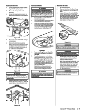
... placing a block of wood (b) between the blade (a) and the deck housing (c). Clean any maintenance, disengage the PTO, engage the parking brake lever, turn the ignition key to cut yourself on the idler spring or between 90-110 ft-lbs. Route the new belt as instructed in personal injury. 4. Remove the deck, (refer to maintain proper blade balance. Always grind each cutting blade edge equally to Deck Removal). 3. On 36" decks, a belt keeper rod (a)will cause excessive vibration, may damage the...
... placing a block of wood (b) between the blade (a) and the deck housing (c). Clean any maintenance, disengage the PTO, engage the parking brake lever, turn the ignition key to cut yourself on the idler spring or between 90-110 ft-lbs. Route the new belt as instructed in personal injury. 4. Remove the deck, (refer to maintain proper blade balance. Always grind each cutting blade edge equally to Deck Removal). 3. On 36" decks, a belt keeper rod (a)will cause excessive vibration, may damage the...

Operation Manual
Page 18
... change the mower's transmission drive belt. Loosen the jam nut (a) and zero out the transmission. CLOSE the neutral lock levers (see Figure 4-22) and move the speed control lever to go right. 18 Section 4- Turn left to verify that there is flush with the end. If the mower tracks (pulls) to the left or right, a tracking adjustment is seated in 1/4-turn increments until the mower tracks straight. Remove the deck...
... change the mower's transmission drive belt. Loosen the jam nut (a) and zero out the transmission. CLOSE the neutral lock levers (see Figure 4-22) and move the speed control lever to go right. 18 Section 4- Turn left to verify that there is flush with the end. If the mower tracks (pulls) to the left or right, a tracking adjustment is seated in 1/4-turn increments until the mower tracks straight. Remove the deck...

Operation Manual
Page 19
... brake not engaged. • Engage parking brake. 4. Product Care 19 Cutting blade loose or unbalanced. • Tighten blade and spindle. 2. Wet grass. • Do not mulch when grass is wet. 3. Mower drifting 1. Uneven tire pressure. • Check and correct tire pressure in disengaged (OFF) position. 2. Excessively high grass. • Mow once at a high cutting height, then mow again at desired height or make a narrower cutting swath. 4. Engine fails to -side deck adjustment. 2. See Engine Operator's Manual. Deck not properly leveled. • Perform side-to start 1. Cutting...
... brake not engaged. • Engage parking brake. 4. Product Care 19 Cutting blade loose or unbalanced. • Tighten blade and spindle. 2. Wet grass. • Do not mulch when grass is wet. 3. Mower drifting 1. Uneven tire pressure. • Check and correct tire pressure in disengaged (OFF) position. 2. Excessively high grass. • Mow once at a high cutting height, then mow again at desired height or make a narrower cutting swath. 4. Engine fails to -side deck adjustment. 2. See Engine Operator's Manual. Deck not properly leveled. • Perform side-to start 1. Cutting...

Operation Manual
Page 20
...Deck Spindle Deck Wheel (48" and 54" Decks) Deck Skid Guard, 36" Deck Deck Skid Guard, 48" & 54" Decks Battery (Electric Start Models Only) Gas Cap Throttle Control Cable (If Equipped) Choke Control (If Equipped) Ignition Key Park Brake Cable, Left Park Brake Cable, Right Chute Assembly Rear Wheel Assembly, 36" Decks, 18 x 6.5-8 Rear Wheel Assembly, 48" & 54" Decks, 634-05474 Front Wheel Assembly, 11 x 4-5 Attachments & Accessories 6 Part Number 59A50009150 59A50008150 59A50004150 59A50003150 59A50006150 59A50005150 59A50007150 Description Double Wheel Sulky Single Wheel Sulky Bagger Mulch...
...Deck Spindle Deck Wheel (48" and 54" Decks) Deck Skid Guard, 36" Deck Deck Skid Guard, 48" & 54" Decks Battery (Electric Start Models Only) Gas Cap Throttle Control Cable (If Equipped) Choke Control (If Equipped) Ignition Key Park Brake Cable, Left Park Brake Cable, Right Chute Assembly Rear Wheel Assembly, 36" Decks, 18 x 6.5-8 Rear Wheel Assembly, 48" & 54" Decks, 634-05474 Front Wheel Assembly, 11 x 4-5 Attachments & Accessories 6 Part Number 59A50009150 59A50008150 59A50004150 59A50003150 59A50006150 59A50005150 59A50007150 Description Double Wheel Sulky Single Wheel Sulky Bagger Mulch...

Operation Manual
Page 22
...off -road spark ignition engine regulations). Any such part repaired or replaced under warranty will be used in the performance of any warranty maintenance or repairs and must be warranted for performance of the required maintenance listed in the written instructions supplied is warranted...service center as soon as fuel tanks, fuel lines, fuel caps, valves, canisters, filters, vapor hoses, clamps, connectors, and other engine or equipment components proximately caused by MTD Consumer Group Inc according to subsection (4) below . Any such part repaired or replaced under the warranty ...
...off -road spark ignition engine regulations). Any such part repaired or replaced under warranty will be used in the performance of any warranty maintenance or repairs and must be warranted for performance of the required maintenance listed in the written instructions supplied is warranted...service center as soon as fuel tanks, fuel lines, fuel caps, valves, canisters, filters, vapor hoses, clamps, connectors, and other engine or equipment components proximately caused by MTD Consumer Group Inc according to subsection (4) below . Any such part repaired or replaced under the warranty ...

Operation Manual
Page 24
... rental expenses to our website at www.mtdcanada.com. Check your property and/or to any part thereof, is repair or replacement of the product as : belts, blades, blade adapters, grass bags, rider deck wheels, seats, and tires. Routine maintenance items such as lubricants, filters, blade sharpening, tune-ups, brake adjustments, clutch adjustments, deck adjustments, and normal deterioration of the exterior finish due to use with respect to others and their respective possessions and...
... rental expenses to our website at www.mtdcanada.com. Check your property and/or to any part thereof, is repair or replacement of the product as : belts, blades, blade adapters, grass bags, rider deck wheels, seats, and tires. Routine maintenance items such as lubricants, filters, blade sharpening, tune-ups, brake adjustments, clutch adjustments, deck adjustments, and normal deterioration of the exterior finish due to use with respect to others and their respective possessions and...


