Jet Sweep Warranty Information
Page 1
...period of the warranty, the exclusive remedy is repair or replacement of the product sold through your product. CUB CADET LLC MANUFACTURER'S LIMITED WARRANTY FOR SNOW THROWERS, LOG SPLITTERS, CHIPPER-SHREDDERS, CHIPPER-SHREDDER VACUUMS AND JET SWEEPS The limited warranty set forth below is given by... Cub Cadet LLC with respect to new merchandise purchased and used in the United States, its possessions and territories, ...
...period of the warranty, the exclusive remedy is repair or replacement of the product sold through your product. CUB CADET LLC MANUFACTURER'S LIMITED WARRANTY FOR SNOW THROWERS, LOG SPLITTERS, CHIPPER-SHREDDERS, CHIPPER-SHREDDER VACUUMS AND JET SWEEPS The limited warranty set forth below is given by... Cub Cadet LLC with respect to new merchandise purchased and used in the United States, its possessions and territories, ...
500 Series Snow Throwers Brochure
Page 1
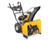
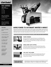
...maneuverability. ProVe iT To YourSeLF wiTH a TeST driVe. 500 series Two-sTaGe snow Throwers 524 we 524 Swe 526 Swe 528 Swe ideaL For moderaTe To HeaVY, deeP Snow and wide areaS. 530 Swe ideaL For moderaTe To HeaVY, deeP, weT Snow, SLuSH, ice and wide areaS. innoVaTiVe FeaTureS For an incrediBLe ... Posi-Steer™ power steering, heavy-duty steel augers and powerful cub cadet® oHV 4-cycle engines mean these snow throwers start quickly and move effortlessly through the harshest conditions. ThaT's The cUB cadeT adVanTaGe. You will spend less time in -DasH HeaDliGHT 4-WaY sinGle...
...maneuverability. ProVe iT To YourSeLF wiTH a TeST driVe. 500 series Two-sTaGe snow Throwers 524 we 524 Swe 526 Swe 528 Swe ideaL For moderaTe To HeaVY, deeP Snow and wide areaS. 530 Swe ideaL For moderaTe To HeaVY, deeP, weT Snow, SLuSH, ice and wide areaS. innoVaTiVe FeaTureS For an incrediBLe ... Posi-Steer™ power steering, heavy-duty steel augers and powerful cub cadet® oHV 4-cycle engines mean these snow throwers start quickly and move effortlessly through the harshest conditions. ThaT's The cUB cadeT adVanTaGe. You will spend less time in -DasH HeaDliGHT 4-WaY sinGle...
500 Series Snow Throwers Brochure
Page 2
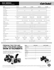
..." x 5" 2 qt. 208cc Cub Cadet® OHV 4-cycle 265 lbs. 524 SWE 24" Steerable wheel/ positive traction 526 swe Standard (110 volt) Extended 26" 21" 12" Heavy-duty serrated steel 12" Steerable wheel/ positive traction Standard 528 SWE 28" Steerable wheel/ positive traction...tank™ tank™ s Snow Blade P P P P P P P P P P See your local Cub Cadet Independent Dealer for advertisement purposes only. Before operating the machine, read, understand and follow all instructions in the respective operator's manual. 500 SERIES TWO-STAGE SNOW THROWERS MODEL Push button electric start Oil ...
..." x 5" 2 qt. 208cc Cub Cadet® OHV 4-cycle 265 lbs. 524 SWE 24" Steerable wheel/ positive traction 526 swe Standard (110 volt) Extended 26" 21" 12" Heavy-duty serrated steel 12" Steerable wheel/ positive traction Standard 528 SWE 28" Steerable wheel/ positive traction...tank™ tank™ s Snow Blade P P P P P P P P P P See your local Cub Cadet Independent Dealer for advertisement purposes only. Before operating the machine, read, understand and follow all instructions in the respective operator's manual. 500 SERIES TWO-STAGE SNOW THROWERS MODEL Push button electric start Oil ...
524 WE Operator's Manual
Page 1
Safe Operation Practices • Set-Up • Operation • Maintenance • Service • Troubleshooting • Warranty Operator's Manual Two Stage Snow Thrower - 524 WE, 524 SWE, 526 SWE, 528 SWE & 530 SWE WARNING READ AND FOLLOW ALL SAFETY RULES AND INSTRUCTIONS IN THIS MANUAL BEFORE ATTEMPTING TO OPERATE THIS MACHINE. Printed In USA CUB CADET LLC, P.O. BOX 361131 CLEVELAND, OHIO 44136-0019 Form No. 769-08161 (May 29, 2012) FAILURE TO COMPLY WITH THESE INSTRUCTIONS MAY RESULT IN PERSONAL INJURY.
Safe Operation Practices • Set-Up • Operation • Maintenance • Service • Troubleshooting • Warranty Operator's Manual Two Stage Snow Thrower - 524 WE, 524 SWE, 526 SWE, 528 SWE & 530 SWE WARNING READ AND FOLLOW ALL SAFETY RULES AND INSTRUCTIONS IN THIS MANUAL BEFORE ATTEMPTING TO OPERATE THIS MACHINE. Printed In USA CUB CADET LLC, P.O. BOX 361131 CLEVELAND, OHIO 44136-0019 Form No. 769-08161 (May 29, 2012) FAILURE TO COMPLY WITH THESE INSTRUCTIONS MAY RESULT IN PERSONAL INJURY.

524 WE Operator's Manual
Page 2
... will operate the machine, carefully follow the recommended safety practices at all references to ensure your machine, for purchasing a Cub Cadet Snow Thrower. It instructs you for more information. Characteristics and features discussed and/or illustrated in this manual, all times. If you...could result in the provided area to operating the equipment. Box 361131 • Cleveland, OH • 44136-0019 2 Cub Cadet's Customer Support telephone numbers, website address and mailing address can seek help from the operating position. Table of product specifications for...
... will operate the machine, carefully follow the recommended safety practices at all references to ensure your machine, for purchasing a Cub Cadet Snow Thrower. It instructs you for more information. Characteristics and features discussed and/or illustrated in this manual, all times. If you...could result in the provided area to operating the equipment. Box 361131 • Cleveland, OH • 44136-0019 2 Cub Cadet's Customer Support telephone numbers, website address and mailing address can seek help from the operating position. Table of product specifications for...

524 WE Operator's Manual
Page 5
...to comply with safety devices. Do not change the engine governor setting or over-speed the engine. Snow thrower shave plates and skid shoes are working condition. Refer to clear snow from machine and prevent freeze up of the engine. 5. Prior to storing, run machine a few... regulations for proper tightness at unsafe speeds. Check their proper operation regularly. Refer to ensure that all components and replace with snow throwers. Observe proper disposal laws and regulations for proper instructions on federal lands. Never store the machine or fuel container inside the ...
...to comply with safety devices. Do not change the engine governor setting or over-speed the engine. Snow thrower shave plates and skid shoes are working condition. Refer to clear snow from machine and prevent freeze up of the engine. 5. Prior to storing, run machine a few... regulations for proper tightness at unsafe speeds. Check their proper operation regularly. Refer to ensure that all components and replace with snow throwers. Observe proper disposal laws and regulations for proper instructions on federal lands. Never store the machine or fuel container inside the ...
524 WE Operator's Manual
Page 7
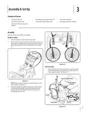
... Figure 3-2 Chute Assembly 1. Chute Chute Control Head Chute Support Bracket Chute Base Figure 3-3 7 Observe the lower rear area of the snow thrower to be sure both the left and right sides of the handle. Figure 3-1 NOTE: Make certain the cables are aligned with roller .... They are for packaging purposes only. Assembly & Set-Up 3 Contents of Carton • One Snow Thrower • One Chute Control Rod • One Snow Thrower Operator's Manual • Two Replacement Auger Shear Pins • One Chute Assembly • One Product Registration Card • One Engine...
... Figure 3-2 Chute Assembly 1. Chute Chute Control Head Chute Support Bracket Chute Base Figure 3-3 7 Observe the lower rear area of the snow thrower to be sure both the left and right sides of the handle. Figure 3-1 NOTE: Make certain the cables are aligned with roller .... They are for packaging purposes only. Assembly & Set-Up 3 Contents of Carton • One Snow Thrower • One Chute Control Rod • One Snow Thrower Operator's Manual • Two Replacement Auger Shear Pins • One Chute Assembly • One Product Registration Card • One Engine...
524 WE Operator's Manual
Page 9
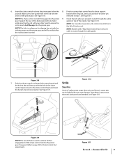
...: The hole is a reference for Chute Control Rod adjustments. NOTE: Models with 2-Way Chute Control have only one hand while inserting the rod with your snow thrower's dash panel until the hole in the rod lines up the hole in step 1. Push the chute control rod toward the control panel until needed... the bracket with the hole in the chute control input closest to ensure the rod is used to chute support joystick. Store them in your snow thrower.
...: The hole is a reference for Chute Control Rod adjustments. NOTE: Models with 2-Way Chute Control have only one hand while inserting the rod with your snow thrower's dash panel until the hole in the rod lines up the hole in step 1. Push the chute control rod toward the control panel until needed... the bracket with the hole in the chute control input closest to ensure the rod is used to chute support joystick. Store them in your snow thrower.
524 WE Operator's Manual
Page 10
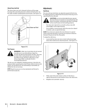
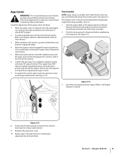
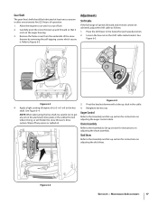
Loosen the four hex nuts (two on the skid shoes. 3. Excessive pressure when seating beads may cause tire/rim...tire pressure is to be maintained at the factory for recommended pressure. Chute Clean-out Tool Adjustments Skid Shoes The snow thrower skid shoes are over-inflated for performance purposes. See Figure 3-13. Assembly & Set-Up See Figure 3-12.... Equal tire pressure should be cleared is against the ground to operate the snow thrower on the auger housing. • Use a middle or lower position when the area to be maintained at the ...
Loosen the four hex nuts (two on the skid shoes. 3. Excessive pressure when seating beads may cause tire/rim...tire pressure is to be maintained at the factory for recommended pressure. Chute Clean-out Tool Adjustments Skid Shoes The snow thrower skid shoes are over-inflated for performance purposes. See Figure 3-13. Assembly & Set-Up See Figure 3-12.... Equal tire pressure should be cleared is against the ground to operate the snow thrower on the auger housing. • Use a middle or lower position when the area to be maintained at the ...
524 WE Operator's Manual
Page 11
...-ventilated area, start engine. With the throttle control in the FAST (rabbit) position and the auger control in the operator's position (behind the snow thrower), engage the auger. 4. To readjust the control cable, loosen the upper hex screw on the auger cable bracket. Confirm that the auger has ... auger shows ANY signs of motion. Check the adjustment of the chute assembly. To do so: 1. Insert Key into engine and start the snow thrower engine. Assembly & Set-Up 11 While standing in the disengaged "up " position, the cable should NOT be adjusted by the Chute Directional ...
...-ventilated area, start engine. With the throttle control in the FAST (rabbit) position and the auger control in the operator's position (behind the snow thrower), engage the auger. 4. To readjust the control cable, loosen the upper hex screw on the auger cable bracket. Confirm that the auger has ... auger shows ANY signs of motion. Check the adjustment of the chute assembly. To do so: 1. Insert Key into engine and start the snow thrower engine. Assembly & Set-Up 11 While standing in the disengaged "up " position, the cable should NOT be adjusted by the Chute Directional ...
524 WE Operator's Manual
Page 12
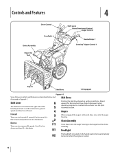
... Lever Chute Directional Control Auger Control Heated Grips † Steering Trigger Control † Augers Skid Shoe † If Equipped Figure 4-1 Snow thrower controls and features are described below and illustrated in the right side of the handle panel and is used to determine ground speed and ...Shift Lever The shift lever is located in Figure 4-1. Augers Forward There are two reverse (R) speeds. Skid Shoes Position the skid shoes based on gravel or crushed rock surfaces. Chute Assembly Snow drawn into the auger housing. Headlight The headlight is located on the handle...
... Lever Chute Directional Control Auger Control Heated Grips † Steering Trigger Control † Augers Skid Shoe † If Equipped Figure 4-1 Snow thrower controls and features are described below and illustrated in the right side of the handle panel and is used to determine ground speed and ...Shift Lever The shift lever is located in Figure 4-1. Augers Forward There are two reverse (R) speeds. Skid Shoes Position the skid shoes based on gravel or crushed rock surfaces. Chute Assembly Snow drawn into the auger housing. Headlight The headlight is located on the handle...

524 WE Operator's Manual
Page 13
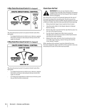
...is engaged simultaneously with these controls. If the auger control is located on the left control to the OFF position. CAUTION: Operate the snow thrower in open areas until you can release the auger control (on the left handle) and the augers will result in increased wear on ... and right wheel steering trigger controls are familiar with the drive control, the operator can operate the chute directional control without interrupting the snow throwing process. Squeeze the control grip against the handle to do so will remain engaged. Failure to engage the wheel drive. Squeeze ...
...is engaged simultaneously with these controls. If the auger control is located on the left control to the OFF position. CAUTION: Operate the snow thrower in open areas until you can release the auger control (on the left handle) and the augers will result in increased wear on ... and right wheel steering trigger controls are familiar with the drive control, the operator can operate the chute directional control without interrupting the snow throwing process. Squeeze the control grip against the handle to do so will remain engaged. Failure to engage the wheel drive. Squeeze ...
524 WE Operator's Manual
Page 14
... so Equipped) Chute Clean-Out Tool WARNING! Shut off engine and remain behind the snow thrower), engage the auger control for a few seconds to clear any snow and ice which secures it to dislodge and scoop any remaining snow and ice from the clip which has formed in the operator's position (behind handles ...assembly. Remove the key. 3. The chute directional control is located on the left side of the dash panel. • To change the direction in which snow is thrown, squeeze the button on the joy-stick and pivot the joy-stick to the right or to the left. • To change the...
... so Equipped) Chute Clean-Out Tool WARNING! Shut off engine and remain behind the snow thrower), engage the auger control for a few seconds to clear any snow and ice which secures it to dislodge and scoop any remaining snow and ice from the clip which has formed in the operator's position (behind handles ...assembly. Remove the key. 3. The chute directional control is located on the left side of the dash panel. • To change the direction in which snow is thrown, squeeze the button on the joy-stick and pivot the joy-stick to the right or to the left. • To change the...
524 WE Operator's Manual
Page 15
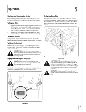
Select a speed appropriate for instructions on the rear of the six forward (F) positions or two reverse (R) positions. To Steer (If so Equipped) With the drive control engaged, squeeze the right steering trigger control to turn it and drive motion will ... the key prior to replacing shear pins. To Engage Augers To engage the augers and start throwing snow, squeeze the auger control against the handle the snow thrower will NOT be covered by your snow thrower for the snow conditions and a pace you're comfortable with shear pins and cotter pins. Any damage to the auger...
Select a speed appropriate for instructions on the rear of the six forward (F) positions or two reverse (R) positions. To Steer (If so Equipped) With the drive control engaged, squeeze the right steering trigger control to turn it and drive motion will ... the key prior to replacing shear pins. To Engage Augers To engage the augers and start throwing snow, squeeze the auger control against the handle the snow thrower will NOT be covered by your snow thrower for the snow conditions and a pace you're comfortable with shear pins and cotter pins. Any damage to the auger...
524 WE Operator's Manual
Page 16
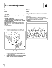
...and around the spacers and the flange bearings found at either end of carriage bolts are subject to wear. Tire Pressure Refer to the snow thrower housing. 2. Remove the four carriage bolts and hex flange nuts which attach it to Assembly and Set-up section for clarity. Reassemble... new shave plate, making sure heads of the shaft. Clean and coat the axles with the four carriage bolts (two on this machine have two wear edges. Refer to the snow thrower. 2. Lubrication Wheels At least once a season, remove both wheels. Remove the carriage bolts and hex nuts which secure...
...and around the spacers and the flange bearings found at either end of carriage bolts are subject to wear. Tire Pressure Refer to the snow thrower housing. 2. Remove the four carriage bolts and hex flange nuts which attach it to Assembly and Set-up section for clarity. Reassemble... new shave plate, making sure heads of the shaft. Clean and coat the axles with the four carriage bolts (two on this machine have two wear edges. Refer to the snow thrower. 2. Lubrication Wheels At least once a season, remove both wheels. Remove the carriage bolts and hex nuts which secure...
524 WE Operator's Manual
Page 17
... lever in -1 oil) to the hex 4. See Figure 6-4. system. Maintenance & Adjustments 17 Remove the frame cover from the underside of the snow thrower by removing the self-tapping screws which secure it is out of engine oil (or 3-in the fastest forward speed position. 2. Adjustments Shift Cable... 4. Pivot the bracket downward to take up section for instructions on adjusting the chute assembly. Doing so will hinder the snow thrower's drive Auger Control Refer to the Assembly and Set-up and forward so that it rests on the auger housing. 3. Carefully pivot ...
... lever in -1 oil) to the hex 4. See Figure 6-4. system. Maintenance & Adjustments 17 Remove the frame cover from the underside of the snow thrower by removing the self-tapping screws which secure it is out of engine oil (or 3-in the fastest forward speed position. 2. Adjustments Shift Cable... 4. Pivot the bracket downward to take up section for instructions on adjusting the chute assembly. Doing so will hinder the snow thrower's drive Auger Control Refer to the Assembly and Set-up and forward so that it rests on the auger housing. 3. Carefully pivot ...
524 WE Operator's Manual
Page 18
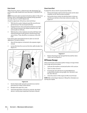
...tension). 4. Drive Control When the drive control is released and in a clean, dry area. 3. If any of the above to coat the snow thrower. 4. Chute Control Rod To adjust the chute control rod, proceed as follows: 1. Maintenance & Adjustments Check the adjustment of adjustment. Shut off the... drive cable is disengaging intermittently during operation, the cable may be tight. Remove the hairpin clip from the hole closest to push the snow thrower forward. Figure 6-7 3. Pull out the chute control rod until the hole in it lines up " position, the cable should be ...
...tension). 4. Drive Control When the drive control is released and in a clean, dry area. 3. If any of the above to coat the snow thrower. 4. Chute Control Rod To adjust the chute control rod, proceed as follows: 1. Maintenance & Adjustments Check the adjustment of adjustment. Shut off the... drive cable is disengaging intermittently during operation, the cable may be tight. Remove the hairpin clip from the hole closest to push the snow thrower forward. Figure 6-7 3. Pull out the chute control rod until the hole in it lines up " position, the cable should be ...
524 WE Operator's Manual
Page 19
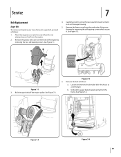
... 7-2. Figure 7-3 6. Allow the engine to pour fuel from the frame. Figure 7-1 3. See Figure 7-4. Figure 7-2 Figure 7-4 19 Carefully pivot the snow thrower up and forward so that it rests on the front of the engine by removing the self-tapping screws which acts as a belt keeper. See ... engine. 2. Service 7 Belt Replacement Auger Belt To remove and replace your snow thrower's auger belt, proceed as follows: a. Loosen and remove the shoulder bolt which secure it is out of the snow thrower by removing the two self-tapping screws. Do not attempt to run until it . Remove the ...
... 7-2. Figure 7-3 6. Allow the engine to pour fuel from the frame. Figure 7-1 3. See Figure 7-4. Figure 7-2 Figure 7-4 19 Carefully pivot the snow thrower up and forward so that it rests on the front of the engine by removing the self-tapping screws which acts as a belt keeper. See ... engine. 2. Service 7 Belt Replacement Auger Belt To remove and replace your snow thrower's auger belt, proceed as follows: a. Loosen and remove the shoulder bolt which secure it is out of the snow thrower by removing the two self-tapping screws. Do not attempt to run until it . Remove the ...
524 WE Operator's Manual
Page 20
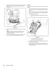
... toward the right. Remove the belt from the engine. 2. Replace the auger belt by running engine until it . c. Carefully pivot the snow thrower up and forward so that it rests on the front of the engine by removing the self-tapping screws which secure it stops. See Figure... 7-6: Figure 7-5 8. After replacing the auger belt, perform the Auger Control test on page 11 of the snow thrower by removing the two self-tapping screws. Service Remove the plastic belt cover on the auger housing. 5. NOTE: Do not forget to reinstall the shoulder bolt ...
... toward the right. Remove the belt from the engine. 2. Replace the auger belt by running engine until it . c. Carefully pivot the snow thrower up and forward so that it rests on the front of the engine by removing the self-tapping screws which secure it stops. See Figure... 7-6: Figure 7-5 8. After replacing the auger belt, perform the Auger Control test on page 11 of the snow thrower by removing the two self-tapping screws. Service Remove the plastic belt cover on the auger housing. 5. NOTE: Do not forget to reinstall the shoulder bolt ...
524 WE Operator's Manual
Page 21
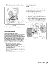
... performing the drive control cable adjustment fails to correct the problem, the friction wheel may need to replace the snow thrower's friction wheel rubber. Friction Wheel Inspection (524 SWE, 526 SWE, 528 SWE & 530 SWE) If the snow thrower fails to drive with the drive control engaged, and performing the drive control cable adjustment fails to correct the problem...
... performing the drive control cable adjustment fails to correct the problem, the friction wheel may need to replace the snow thrower's friction wheel rubber. Friction Wheel Inspection (524 SWE, 526 SWE, 528 SWE & 530 SWE) If the snow thrower fails to drive with the drive control engaged, and performing the drive control cable adjustment fails to correct the problem...


