
Operation Manual
Page 2
... Thoroughly inspect the area where the equipment is in moving parts. Do not operate without proper instruction. 5. Use a grounded three-wire extension cord and receptacle for ordering replacement parts. 2. Never attempt to assemble and operate. Read, understand, and follow all control levers before attempting to make any type of power equipment, carelessness or error on the part of age to the eyes. 2. Children 14 and over...
... Thoroughly inspect the area where the equipment is in moving parts. Do not operate without proper instruction. 5. Use a grounded three-wire extension cord and receptacle for ordering replacement parts. 2. Never attempt to assemble and operate. Read, understand, and follow all control levers before attempting to make any type of power equipment, carelessness or error on the part of age to the eyes. 2. Children 14 and over...

Operation Manual
Page 3
... fuel is extremely flammable and the vapors are explosive. Repair any damage before storing. 11. SAFE OPERATION PRACTICES SAFE HANDLING OF GASOLINE To avoid personal injury or property damage use extreme care in the auger housing or chute assembly. Replace gasoline cap and tighten securely. 8. If possible, remove gas-powered equipment from your skin and change clothing immediately. 9. Never operate machine at least 5 minutes before starting the engine...
... fuel is extremely flammable and the vapors are explosive. Repair any damage before storing. 11. SAFE OPERATION PRACTICES SAFE HANDLING OF GASOLINE To avoid personal injury or property damage use extreme care in the auger housing or chute assembly. Replace gasoline cap and tighten securely. 8. If possible, remove gas-powered equipment from your skin and change clothing immediately. 9. Never operate machine at least 5 minutes before starting the engine...

Operation Manual
Page 4
... control levers, stop . 3. Check bolts and screws for any way. At the end of auger. 10. Use only attachments and accessories approved by an authorized service dealer to wear and damage. Observe proper disposal laws and regulations for cracks or leaks. Check fuel line, tank, cap, and fittings frequently for gas, oil, etc. Failure to a complete stop the engine, remove the safety key or disconnect spark plug wire. Wait until the auger...
... control levers, stop . 3. Check bolts and screws for any way. At the end of auger. 10. Use only attachments and accessories approved by an authorized service dealer to wear and damage. Observe proper disposal laws and regulations for cracks or leaks. Check fuel line, tank, cap, and fittings frequently for gas, oil, etc. Failure to a complete stop the engine, remove the safety key or disconnect spark plug wire. Wait until the auger...

Operation Manual
Page 5
... the use of the snow blower to clear the auger housing, never use your hand. WARNING- Do not touch. AVOID AMPUTATION INJURY, AUGER HOUSING: Do not put hands near or into the discharge chute while the engine is running . ELECTRICAL SHOCK: Do not plug in and use clean-out tool to persons who read, understand and follow all warnings and instructions on the snow blower and engine. Always use the engine's electric starter in...
... the use of the snow blower to clear the auger housing, never use your hand. WARNING- Do not touch. AVOID AMPUTATION INJURY, AUGER HOUSING: Do not put hands near or into the discharge chute while the engine is running . ELECTRICAL SHOCK: Do not plug in and use clean-out tool to persons who read, understand and follow all warnings and instructions on the snow blower and engine. Always use the engine's electric starter in...
Operation Manual
Page 6
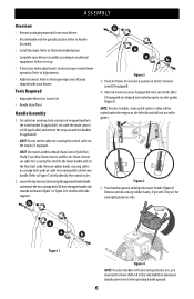
... chute control rod or upper handle to ensure proper snow blower operation. NOTE: On select models, chute-pitch control cables will not use roller guides. Remove rubber bands securing cables to carriage bolts and cut the cable tie securing the control cables to lower handle. Remove and discard any rubber bands, if present. Tools Required • Adjustable Wrench or Socket Set • Needle Nose Pliers Handle Assembly 1. NOTE: Do not cut cable tie securing shift rod to the engine...
... chute control rod or upper handle to ensure proper snow blower operation. NOTE: On select models, chute-pitch control cables will not use roller guides. Remove rubber bands securing cables to carriage bolts and cut the cable tie securing the control cables to lower handle. Remove and discard any rubber bands, if present. Tools Required • Adjustable Wrench or Socket Set • Needle Nose Pliers Handle Assembly 1. NOTE: Do not cut cable tie securing shift rod to the engine...
Operation Manual
Page 7
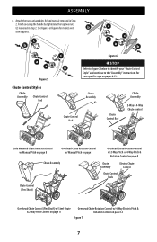
... & Rotation Control on pages 8-13. See Figure 5 or Figure 6 for your specific style on page 12 Figure 7 7 Finish securing the handle by tightening the top two nuts (c) loosened in Step 2. Attach the two carriage bolts (b) and nuts (a) removed in Step 2. c b c c a a b c a a b Figure 5 Figure 6 STOP Refer to Figure 7 below to identify your "Chute Control Style" and continue to the "Assembly" instructions for models with b side supports. ASSEMBLY 6.
... & Rotation Control on pages 8-13. See Figure 5 or Figure 6 for your specific style on page 12 Figure 7 7 Finish securing the handle by tightening the top two nuts (c) loosened in Step 2. Attach the two carriage bolts (b) and nuts (a) removed in Step 2. c b c c a a b c a a b Figure 5 Figure 6 STOP Refer to Figure 7 below to identify your "Chute Control Style" and continue to the "Assembly" instructions for models with b side supports. ASSEMBLY 6.
Operation Manual
Page 8
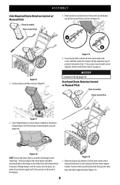
... Set-Up (page 14). The lower edge of chute control rod into place. Figure 12 1. ASSEMBLY Side Mounted Chute Rotation Control w/ Manual Pitch Chute Assembly Chute Control Rod 3. If flange keepers will click into place, use palm of your hand to apply swift, firm pressure to the flange on page 16. Position chute assembly over chute base and chute support bracket (Figure 13). 8 Remove wing nut (a) and hex screw (b) from chute control head and clevis pin...
... Set-Up (page 14). The lower edge of chute control rod into place. Figure 12 1. ASSEMBLY Side Mounted Chute Rotation Control w/ Manual Pitch Chute Assembly Chute Control Rod 3. If flange keepers will click into place, use palm of your hand to apply swift, firm pressure to the flange on page 16. Position chute assembly over chute base and chute support bracket (Figure 13). 8 Remove wing nut (a) and hex screw (b) from chute control head and clevis pin...

Operation Manual
Page 11
... chute control head to chute support bracket with hairpin clip (a) removed in Step 1. Remove lock nuts (a) and hex screws (b)from rear of chute control rod into rear of the chute control rod. 4. STOP Continue to Product Care section for Chute Control Rod adjustments. 8. a b Figure 26 1. Refer to Set-Up (page 14). Overhead Chute Control (Flex Shaft) w/ Steel Chute & 2-Way Pitch Control Steel Chute Assembly 2-Way Pitch Control Chute Base Chute Support Bracket Figure 27 2. Place steel chute assembly onto chute base and chute control head...
... chute control head to chute support bracket with hairpin clip (a) removed in Step 1. Remove lock nuts (a) and hex screws (b)from rear of chute control rod into rear of the chute control rod. 4. STOP Continue to Product Care section for Chute Control Rod adjustments. 8. a b Figure 26 1. Refer to Set-Up (page 14). Overhead Chute Control (Flex Shaft) w/ Steel Chute & 2-Way Pitch Control Steel Chute Assembly 2-Way Pitch Control Chute Base Chute Support Bracket Figure 27 2. Place steel chute assembly onto chute base and chute control head...
Operation Manual
Page 12
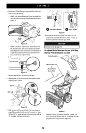
... chute control rod coupling under handle panel. A Non-Hydro Models B Hydro Models Figure 33 10. Make sure the shift lever on end of flex shaft into chute control rod coupling under handle panel (Figure 30). ASSEMBLY 6. Insert other end of the transmission is in Step 8 (Figure 32). Remove cotter pin (a), wing nut (b) and hex screw (c) from chute control head. Make sure to Set-Up (page 14). Overhead Chute Rotation Control w/ 4-Way Electric Pitch & Rotation Control Chute Assembly...
... chute control rod coupling under handle panel. A Non-Hydro Models B Hydro Models Figure 33 10. Make sure the shift lever on end of flex shaft into chute control rod coupling under handle panel (Figure 30). ASSEMBLY 6. Insert other end of the transmission is in Step 8 (Figure 32). Remove cotter pin (a), wing nut (b) and hex screw (c) from chute control head. Make sure to Set-Up (page 14). Overhead Chute Rotation Control w/ 4-Way Electric Pitch & Rotation Control Chute Assembly...
Operation Manual
Page 13
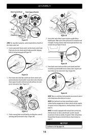
... cotter pin (e) removed in Step 1 (Figure 40). STOP Continue to chute control head is positioned above lower handle. Insert round end of chute assembly, if required. Push rod as far into coupler below handle panel. Make sure to Adjustments, Overhead Chute Control on page 22. Secure chute control head to chute support bracket with manual chute control rods, the hole closest to Set-Up (page 14). 13 Push chute control rod toward the control panel...
... cotter pin (e) removed in Step 1 (Figure 40). STOP Continue to chute control head is positioned above lower handle. Insert round end of chute assembly, if required. Push rod as far into coupler below handle panel. Make sure to Adjustments, Overhead Chute Control on page 22. Secure chute control head to chute support bracket with manual chute control rods, the hole closest to Set-Up (page 14). 13 Push chute control rod toward the control panel...

Operation Manual
Page 14
...-Adjustable 1. Check that secure each drift cutter, and remove them in a safe place until needed. Remove two carriage bolts (a) and lock nuts (b)that all cables are provided in the rear of auger housing (Figure 44). 14 b a Figure 43 2. NOTE: The number of cables routed through cable guide on top of the engine and/or through the wire guide below the chute control head (Figure 41). Attach drift cutters with 2-way or 4-way chute controls, electric chute control...
...-Adjustable 1. Check that secure each drift cutter, and remove them in a safe place until needed. Remove two carriage bolts (a) and lock nuts (b)that all cables are provided in the rear of auger housing (Figure 44). 14 b a Figure 43 2. NOTE: The number of cables routed through cable guide on top of the engine and/or through the wire guide below the chute control head (Figure 41). Attach drift cutters with 2-way or 4-way chute controls, electric chute control...
Operation Manual
Page 15
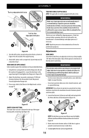
... shoes. 1. Check tire pressure before operating. Move skid shoes to carriage bolts (b). 15 Make certain entire bottom surface of the auger a housing with carriage bolts (a) and wing nuts (b) removed in position for maximum clearance between the shave plate (e) and the ground. Figure 46 3. Turn the drift cutters around and position them upward or downward, if desired, prior to operating. SKID SHOES Snow blower skid shoes...
... shoes. 1. Check tire pressure before operating. Move skid shoes to carriage bolts (b). 15 Make certain entire bottom surface of the auger a housing with carriage bolts (a) and wing nuts (b) removed in position for maximum clearance between the shave plate (e) and the ground. Figure 46 3. Turn the drift cutters around and position them upward or downward, if desired, prior to operating. SKID SHOES Snow blower skid shoes...

Operation Manual
Page 16
... rear skid shoe nuts (a) on front of chute control head. 1. Loosen the two carriage bolts (a) and wing nuts (b) that it is out of auger housing. Slide the drift cutters to chute assembly on left side of chute assembly. Remove hairpin clip (a) from the engine. Remove safety key or disconnect spark plug wire. 2. b b Figure 48 2. MANUAL CHUTE PITCH ADJUSTMENT (IF EQUIPPED) NOTE: For models without manual chute pitch, see Controls and Operation on front of auger housing. 3. a Figure 51...
... rear skid shoe nuts (a) on front of chute control head. 1. Loosen the two carriage bolts (a) and wing nuts (b) that it is out of auger housing. Slide the drift cutters to chute assembly on left side of chute assembly. Remove hairpin clip (a) from the engine. Remove safety key or disconnect spark plug wire. 2. b b Figure 48 2. MANUAL CHUTE PITCH ADJUSTMENT (IF EQUIPPED) NOTE: For models without manual chute pitch, see Controls and Operation on front of auger housing. 3. a Figure 51...

Operation Manual
Page 17
... engine, remove safety key or disconnect spark plug wire. Place shift lever in fastest forward speed position. 2. Repeat this several times. 5. Reinstall and securely tighten all adjustments to one of the alternate holes in cable. 4. Place shift lever in fastest forward speed position. 2. If further adjustment is released and in the operator's position (behind the handles), depress the auger control lever to verify proper adjustment has been achieved. ADJUSTMENTS a a a b b b b b d c c c c Figure 53 NOTE: 3-Stage model...
... engine, remove safety key or disconnect spark plug wire. Place shift lever in fastest forward speed position. 2. Repeat this several times. 5. Reinstall and securely tighten all adjustments to one of the alternate holes in cable. 4. Place shift lever in fastest forward speed position. 2. If further adjustment is released and in the operator's position (behind the handles), depress the auger control lever to verify proper adjustment has been achieved. ADJUSTMENTS a a a b b b b b d c c c c Figure 53 NOTE: 3-Stage model...

Operation Manual
Page 18
... present in drive cable or if drive is in need of drive control lever as necessary until it lines up with drive control lever released, move shift lever back and forth between the R2 position and the F6 position several times. Loosen lower hex screw (a) on drive cable bracket (b) (Figure 59). With drive control lever released, push snow blower gently forward. Position bracket upward to provide more slack (or downward to the Engine Operator's Manual. Check for information...
... present in drive cable or if drive is in need of drive control lever as necessary until it lines up with drive control lever released, move shift lever back and forth between the R2 position and the F6 position several times. Loosen lower hex screw (a) on drive cable bracket (b) (Figure 59). With drive control lever released, push snow blower gently forward. Position bracket upward to provide more slack (or downward to the Engine Operator's Manual. Check for information...

Operation Manual
Page 20
... transmission models. SHIFT LEVER (6-SPEED TRANSMISSION) (IF EQUIPPED) The shift lever is located on the handle panel and is operating safely and properly. Adjust upward for the surface conditions and the snow to the left or right side of the handle panel is/are automatically turned ON when the engine is discharged out the chute assembly. DRIVE CONTROL LEVER/AUGER CLUTCH LOCK* (IF EQUIPPED) The drive control lever is the fastest. Release to stop augers and wheel drive. G. Position...
... transmission models. SHIFT LEVER (6-SPEED TRANSMISSION) (IF EQUIPPED) The shift lever is located on the handle panel and is operating safely and properly. Adjust upward for the surface conditions and the snow to the left or right side of the handle panel is/are automatically turned ON when the engine is discharged out the chute assembly. DRIVE CONTROL LEVER/AUGER CLUTCH LOCK* (IF EQUIPPED) The drive control lever is the fastest. Release to stop augers and wheel drive. G. Position...

Operation Manual
Page 24
... head shear pins (b) - If the augers will NOT be covered by your snow blower's warranty. Re-fasten the clean-out tool to the spiral shaft using round head shear pins (a) - While standing in the operator's position (behind the snow blower), engage the auger control lever for a few seconds to the auger gearbox or other than OEM Part No. 738-04124A (round head replacement shear pins), 738-05273 (black colored, round head replacement shear pins) or 73806654 (hex head replacement shear pins). OEM Part No. 738-04124A. 3-STAGE SNOW BLOWER REPLACEMENT SHEAR PINS...
... head shear pins (b) - If the augers will NOT be covered by your snow blower's warranty. Re-fasten the clean-out tool to the spiral shaft using round head shear pins (a) - While standing in the operator's position (behind the snow blower), engage the auger control lever for a few seconds to the auger gearbox or other than OEM Part No. 738-04124A (round head replacement shear pins), 738-05273 (black colored, round head replacement shear pins) or 73806654 (hex head replacement shear pins). OEM Part No. 738-04124A. 3-STAGE SNOW BLOWER REPLACEMENT SHEAR PINS...
Operation Manual
Page 25
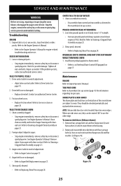
... 76 c b b 25 SERVICE AND MAINTENANCE WARNING Before servicing, repairing or inspecting the snow blower, disengage the auger control lever. Repair as directed in depth. • Increase ground speed and always operate snow blower engine at FULL throttle. FAILS TO PROPEL ITSELF 1. FAILS TO DISCHARGE SNOW 1. Chute assembly clogged. • Stop engine immediately, remove safety key or disconnect spark plug wire. Chute assembled incorrectly. • Disassemble chute control and reassemble as needed. PUSHES SNOW INSTEAD OF THROWING 1. Remove four carriage bolts (a) and hex...
... 76 c b b 25 SERVICE AND MAINTENANCE WARNING Before servicing, repairing or inspecting the snow blower, disengage the auger control lever. Repair as directed in depth. • Increase ground speed and always operate snow blower engine at FULL throttle. FAILS TO PROPEL ITSELF 1. FAILS TO DISCHARGE SNOW 1. Chute assembly clogged. • Stop engine immediately, remove safety key or disconnect spark plug wire. Chute assembled incorrectly. • Disassemble chute control and reassemble as needed. PUSHES SNOW INSTEAD OF THROWING 1. Remove four carriage bolts (a) and hex...

Operation Manual
Page 26
... remain in -1 oil. Lubrication WHEELS At least once a season, remove both wheels and auger housing on auger housing. 3. SERVICE AND MAINTENANCE To remove shave plate: 1. Remove frame cover from the engine. Figure 79 NOTE: When lubricating hex shaft, be careful not to run until next season, follow the storage instructions below. 1. a b Figure 77 4. Clean and coat axles with 3-in the upright position with both wheels. SIDE MOUNTED CHUTE ROTATION CONTROL (IF EQUIPPED...
... remain in -1 oil. Lubrication WHEELS At least once a season, remove both wheels and auger housing on auger housing. 3. SERVICE AND MAINTENANCE To remove shave plate: 1. Remove frame cover from the engine. Figure 79 NOTE: When lubricating hex shaft, be careful not to run until next season, follow the storage instructions below. 1. a b Figure 77 4. Clean and coat axles with 3-in the upright position with both wheels. SIDE MOUNTED CHUTE ROTATION CONTROL (IF EQUIPPED...

Operation Manual
Page 28
... cover from engine. Allow engine to drain fuel from underside by removing four selftapping screws (Figure 78). 4. Do not attempt to run until it rests on auger housing. 4. Carefully pivot snow blower up and forward so that it between support bracket and auger pulley (Figure 85). Figure 86 5. FRICTION WHEEL INSPECTION (STEERABLE 500 AND 800 SERIES & NON-STEERABLE SINGLE SPEED 600 SERIES) If snow blower fails to drive with drive control lever engaged, and performing drive control cable adjustment...
... cover from engine. Allow engine to drain fuel from underside by removing four selftapping screws (Figure 78). 4. Do not attempt to run until it rests on auger housing. 4. Carefully pivot snow blower up and forward so that it between support bracket and auger pulley (Figure 85). Figure 86 5. FRICTION WHEEL INSPECTION (STEERABLE 500 AND 800 SERIES & NON-STEERABLE SINGLE SPEED 600 SERIES) If snow blower fails to drive with drive control lever engaged, and performing drive control cable adjustment...

