Cub Cadet 2X 30 inch MAX Support and Manuals
Get Help and Manuals for this Cub Cadet item

View All Support Options Below
Free Cub Cadet 2X 30 inch MAX manuals!
Problems with Cub Cadet 2X 30 inch MAX?
Ask a Question
Free Cub Cadet 2X 30 inch MAX manuals!
Problems with Cub Cadet 2X 30 inch MAX?
Ask a Question
Popular Cub Cadet 2X 30 inch MAX Manual Pages
Operation Manual - Page 1
NOTE: This Operator's Manual covers several models. Features may result in this manual before attempting to comply with a local authorized service dealer. Model Number Serial Number
WARNING
Read and follow all safety rules and instructions in personal injury - SAVE THESE INSTRUCTIONS.
Failure to operate this manual are applicable to cause cancer and birth defects or ...
Operation Manual - Page 4

... with snow blowers. MAINTENANCE & STORAGE 1. Before cleaning, repairing, or inspecting machine, disengage all components and replace with the governor setting can let go. Remain behind handles until resistance is an open flame, spark or pilot light such as necessary.
8. Maintain or replace safety and instruction labels, as a water heater, furnace, clothes dryer, etc...
Operation Manual - Page 6
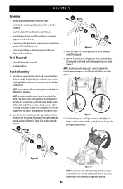
...set aside the chute control rod (if applicable) and remove the wrap around the handles (if applicable). NOTE: On models with Overhead Chute Control (with side supports. Place shift lever in roller guides (Figure 3). NOTE: On select models... Set-up.
• If necessary make adjustments to Handle Assembly.
• Install the chute.
Tools Required
• Adjustable Wrench or Socket Set
...
Operation Manual - Page 7
c b
c
c a
a b
c
a
a
b
Figure 5
Figure 6
STOP
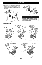
Refer to Figure 7 below to the "Assembly" instructions for models with
b
side supports. See Figure 5 or Figure 6 for your "Chute Control Style" and continue to identify your specific style on page 12
Figure 7
7 Chute Control Styles
Chute Assembly
Chute Control Rod
Chute Assembly
Chute Control Rod
Chute Control Rod
Chute Assembly
...
Operation Manual - Page 8
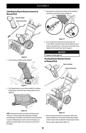
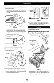
Overhead Chute Rotation Control w/ Manual Pitch
Chute Assembly
Chute Control Rod
Figure 9
2. Figure 10
NOTE: Ensure the lower chute is secured to Set-Up (page 14). Figure 12
1. Position ...back of chute control rod into place.
Position chute assembly over chute base and chute support bracket (Figure 13).
8 Flange keepers will not easily click into place when properly secured...
Operation Manual - Page 12
...31
7.
A Non-Hydro Models B Hydro Models
Figure 33 10.
Remove... cotter pin (a) and washer (b) from ferrule on the back of the transmission is in Step 8 (Figure 32). Remove cotter pin (a), wing nut (b) and hex screw (c) from chute support...need to Set-Up ...8226; Models with ...models without hydro transmission or Detail "B" for models with Electric Chute Control - Figure...
Operation Manual - Page 13
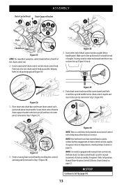
...is positioned above lower handle. NOTE: For models equipped with manual chute control rods, the hole closest to ...Set-Up (page 14).
13 Finish securing chute control head by installing hex screw (c)
and wing nut (b) removed in Step 1 (Figure 37). Figure 36
3. a
e
Figure 37 4.
Refer to the left of chute control rod into chute control head. ASSEMBLY
Chute Control Head Chute Support...
Operation Manual - Page 15
...15.
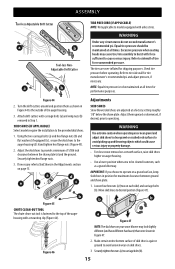
Make certain entire bottom surface of 1/8th inch clearance between ground and shave plate.
1. ASSEMBLY
Tool...(b).
15 Equal tire pressure should be maintained at a factory setting roughly 1/8" below the shave plate.
The tires are adjusted...Figure 44
Adjustments
2. SKID SHOES (IF APPLICABLE) Select models require the installation to cause serious injury. Adjust the skid shoes to ...
Operation Manual - Page 17

... position. 2. Wait for ALL moving parts to take up slack in the shift cable index bracket. a
b
Figure 55 SHIFT ROD (IF EQUIPPED) If full range of 2 mounting positions. Reinstall and securely tighten all instructions below. Re-tighten hex nut. 5. AUGER CONTROL
WARNING
Prior to verify your Engine Operator's Manual.
3. In a well-ventilated area...
Operation Manual - Page 18

...control. If necessary
repeat Steps 2-4 to the Engine Operator's Manual. 2. ADJUSTMENTS
2. DRIVE CONTROL (NON-HYDRO MODELS) (IF EQUIPPED) When drive control lever is released and ...). Loosen lower hex screw (a) on drive cable bracket (b)
(Figure 59). A
B
NON-HYDRO MODELS
HYDRO MODELS
Figure 57
4. If any of adjustment. 1. Position drive cable bracket upward to provide more slack ...
Operation Manual - Page 20

...: Refer to the Auger Control information in the Assembly & Set-Up section prior to be cleared. G. H.
I.
B. Adjust...models except the hydro transmission models. ENGINE CONTROLS Refer to your Engine Operator's Manual for location and description of travel. SKID SHOES Skid shoes provide the proper clearance of the handle panel is/are from yours.
Read and follow all instructions...
Operation Manual - Page 21
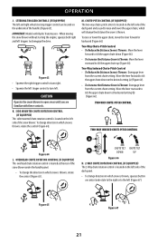
... in which snow is Thrown: Disengage lever from the current chute setting. OVERHEAD CHUTE ROTATION CONTROL (IF EQUIPPED) The overhead chute rotation ...Disengage lever
from the current chute setting.
M.
Move the lever rearward to tilt the upper chute down to the desired setting (a) (Figure 66). •...the desired setting (b) (Figure 66). TWO-WAY CHUTE-PITCH CONTROL
TWO-WAY ...
Operation Manual - Page 25
...Auger Belt Replacement on page 17.
4. Engine fails to on Overhead Chute Control (If Equipped) on page 23.
2. If the problem persists, contact an authorized service center. Insufficient preload applied to chute control.
• Refer to start, runs erratic, skips (hesitates) or idles
poorly. Troubleshooting
ENGINE 1. Refer to prevent unintended starting.
See Engine Operator's Manual...
Operation Manual - Page 26

...
hex shaft (Figure 79). NON-HYDRO MODELS (IF EQUIPPED) The friction wheel hex ... to Engine Operator's Manual for information on page 26. 3. NOTE: Refer to run until it is out of fuel. Lubricate machine as instructed on storing your engine...out of fuel. IMPORTANT: When storing or when it is not being serviced, it rests on the auger housing. 3. Lubrication
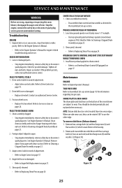
WHEELS At least once...
Operation Manual - Page 28

...to correct problem, the friction wheel may need to have drive belt replaced or contact Customer Support. SERVICE AND ...replaced or contact Customer Support. To inspect friction wheel, proceed as follows: 1.
Remove right-hand wheel by following instructions in Assembly & Set-Up section (page 17). Ball Bearing
a
Figure 87 NOTE: Be careful not to frame after installing a replacement...
Cub Cadet 2X 30 inch MAX Reviews
We have not received any reviews for Cub Cadet yet.