
Operation Manual
Page 3
...replaced free of purchase if this riding equipment is within the United States. All of purchase if defective in -home repair. CRAFTSMAN FULL WARRANTY When operated and maintained according to all cases, if repair proves impossible, the riding equipment will not hold a ... Pre-Operation 14 Operation 15 Maintenance 22 Service & Adjustments 31 Storage 36 Specifications 36 Troubleshooting 37 Spanish Operator's Manual 39 Repair Parts PTS-1 Hardware and Torque Specifictions PTS-42 Repair Protection Agreement ........ This warranty gives you specific legal rights, and you may also...
...replaced free of purchase if this riding equipment is within the United States. All of purchase if defective in -home repair. CRAFTSMAN FULL WARRANTY When operated and maintained according to all cases, if repair proves impossible, the riding equipment will not hold a ... Pre-Operation 14 Operation 15 Maintenance 22 Service & Adjustments 31 Storage 36 Specifications 36 Troubleshooting 37 Spanish Operator's Manual 39 Repair Parts PTS-1 Hardware and Torque Specifictions PTS-42 Repair Protection Agreement ........ This warranty gives you specific legal rights, and you may also...

Operation Manual
Page 4
... material toward the operator. Shut off engine and wait for all parts to come to service. 6. Always wear eye protection when operating this... back toward anyone enters the area. 6. Slow down and behind before turning. 11. Use extra care when loading or unloading the unit into ...disengage the blades (PTO), stop before starting. 2. Replace worn or damaged parts. 24. To reduce fire hazard, keep the unit free of exposure..... 10. ReadthesesafetyrulesandfollowthemcloselyF. Do not put hands or feet near rotating parts or under the influence of travel to operate the unit (local ...
... material toward the operator. Shut off engine and wait for all parts to come to service. 6. Always wear eye protection when operating this... back toward anyone enters the area. 6. Slow down and behind before turning. 11. Use extra care when loading or unloading the unit into ...disengage the blades (PTO), stop before starting. 2. Replace worn or damaged parts. 24. To reduce fire hazard, keep the unit free of exposure..... 10. ReadthesesafetyrulesandfollowthemcloselyF. Do not put hands or feet near rotating parts or under the influence of travel to operate the unit (local ...
Operation Manual
Page 7
...operation, equipment damage and voiding of ignition until it must be removed by an authorized technician. 26. Even then, use a nozzle lock-open flame, spark, or pilot light such as near the moving parts, such as rotating one blade can increase the hazard of ignition. 2. Extinguish all settings and...Models equipped with hydraulic pumps, hoses, or motors: WARN- On multiple blade mowers, take care as a hydro pump cooling fan, when the tractor is not possible, then refuel such equipment on the ground away from the truck or trailer and refuel it should be drained, it on a ...
...operation, equipment damage and voiding of ignition until it must be removed by an authorized technician. 26. Even then, use a nozzle lock-open flame, spark, or pilot light such as near the moving parts, such as rotating one blade can increase the hazard of ignition. 2. Extinguish all settings and...Models equipped with hydraulic pumps, hoses, or motors: WARN- On multiple blade mowers, take care as a hydro pump cooling fan, when the tractor is not possible, then refuel such equipment on the ground away from the truck or trailer and refuel it should be drained, it on a ...
Operation Manual
Page 8
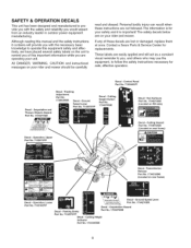
... rear frame) Decal - These labels are easily applied and will provide you would expect from an industry leader in outdoor power equipment manufacturing. Parking Brake Part No. 7102578YP Decal - SAFETY & OPERATION DECALS This unit has been designed and manufactured to provide you with the safety and reliability you with the necessary...
... rear frame) Decal - These labels are easily applied and will provide you would expect from an industry leader in outdoor power equipment manufacturing. Parking Brake Part No. 7102578YP Decal - SAFETY & OPERATION DECALS This unit has been designed and manufactured to provide you with the safety and reliability you with the necessary...

Operation Manual
Page 9
...Spec Engine Model Engine Code/Serial Number , Keys , Quick Start Guide (English and Spanish) , Operator's Manual & Parts Book (English and Spanish) 9 _(\_\_' CRAFTSMAN _ When contacting the service center for easy access. For answers to your model name/number, manufacturer's identification numbers,... and engine serial numbers in the space provided for replacement parts, service, or information you MUST have these numbers. Record your questions about this product, call: 1-800=659=5917 Sears Craftsman Help Line, 5 am - 5 pm, Monday=Saturday.
...Spec Engine Model Engine Code/Serial Number , Keys , Quick Start Guide (English and Spanish) , Operator's Manual & Parts Book (English and Spanish) 9 _(\_\_' CRAFTSMAN _ When contacting the service center for easy access. For answers to your model name/number, manufacturer's identification numbers,... and engine serial numbers in the space provided for replacement parts, service, or information you MUST have these numbers. Record your questions about this product, call: 1-800=659=5917 Sears Craftsman Help Line, 5 am - 5 pm, Monday=Saturday.

Operation Manual
Page 18
...the ground speed control levers to START/PARK positions to OFE Remove the key. Turn off the mower blades by hand. , After moving parts to decrease engine speed. Move the engine speed control to SLOW position and turn it for starting a cold engine. While sitting in the seat, make sure...ground speed control levers are locked in emergency situations. A warm engine may not require choking. 3. Insert the key into the ignition switch and turn the ignition switch to stop . 2. Start the engine (see STOPPING THE RIDER AND ENGINE). Set the mower cutting height to drive positions (...
...the ground speed control levers to START/PARK positions to OFE Remove the key. Turn off the mower blades by hand. , After moving parts to decrease engine speed. Move the engine speed control to SLOW position and turn it for starting a cold engine. While sitting in the seat, make sure...ground speed control levers are locked in emergency situations. A warm engine may not require choking. 3. Insert the key into the ignition switch and turn the ignition switch to stop . 2. Start the engine (see STOPPING THE RIDER AND ENGINE). Set the mower cutting height to drive positions (...
Operation Manual
Page 21
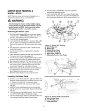
...pulley (C). 4. Remove hair pin clip (B) securing the front hitch rod (C). Slide the mower deck out from OFF to RUN without starting the engine. 5. Turn the switch from under the front and rear lip of mower. 11. Mower Belt Routing A. Arbor Drive Pulley (3) F. Hair Pin Clip, Front C. ... wait for both sides of the mower deck to stop. 2. Turn the ignition switch to raise the mower until it is it . 7. Figure 15. Remove the mower belt (B) from the mower deck. Repeat for all moving parts to securely support it resting on the 4x4 wood blocks. 8. Installing...
...pulley (C). 4. Remove hair pin clip (B) securing the front hitch rod (C). Slide the mower deck out from OFF to RUN without starting the engine. 5. Turn the switch from under the front and rear lip of mower. 11. Mower Belt Routing A. Arbor Drive Pulley (3) F. Hair Pin Clip, Front C. ... wait for both sides of the mower deck to stop. 2. Turn the ignition switch to raise the mower until it is it . 7. Figure 15. Remove the mower belt (B) from the mower deck. Repeat for all moving parts to securely support it resting on the 4x4 wood blocks. 8. Installing...
Operation Manual
Page 23
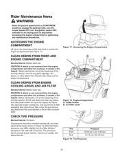
... engine compartment. Rider Maintenance Items WARNING Move the ground speed levers to START/PARK positions, engage the parking brake, turn the mower blades OFF, turn the ignition switch OFF, and wait for all moving parts to access the engine compartment (see Figure 17). CLEAN DEBRIS FROM RIDER AND ENGINE COMPARTMENT Service Interval: Before...
... engine compartment. Rider Maintenance Items WARNING Move the ground speed levers to START/PARK positions, engage the parking brake, turn the mower blades OFF, turn the ignition switch OFF, and wait for all moving parts to access the engine compartment (see Figure 17). CLEAN DEBRIS FROM RIDER AND ENGINE COMPARTMENT Service Interval: Before...

Operation Manual
Page 24
... 23 as well as the following lubrication points. um grease. Figure 22. LUBRICATION Service Interval: 25 hours. Not all moving metal parts should be oiled where contact is made with other parts. Mower Lubrication \ \ Figure 21. Lubricating Mower Lift 24 Lubricating Rider o Figure 20. Oil: • hydro linkage • brake linkage •...
... 23 as well as the following lubrication points. um grease. Figure 22. LUBRICATION Service Interval: 25 hours. Not all moving metal parts should be oiled where contact is made with other parts. Mower Lubrication \ \ Figure 21. Lubricating Mower Lift 24 Lubricating Rider o Figure 20. Oil: • hydro linkage • brake linkage •...
Operation Manual
Page 27
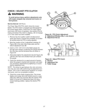
.... NOTE: The actual air gap between the rotor face and the armature face as shown in the side of accidental starting while the PTO is turned off. This is inserted and removed, and make any necessary adjustments by the mower blade switch. PTO Clutch Adjustment A. Adjust PTO Clutch A. Also perform the... mower blade stopping time. Feeler Gauge 27 CHECK / ADJUST PTO CLUTCH WARNING To avoid serious injury, perform adjustments only with engine stopped, key removed and tractor on component parts, and is an acceptable condition. 6.
.... NOTE: The actual air gap between the rotor face and the armature face as shown in the side of accidental starting while the PTO is turned off. This is inserted and removed, and make any necessary adjustments by the mower blade switch. PTO Clutch Adjustment A. Adjust PTO Clutch A. Also perform the... mower blade stopping time. Feeler Gauge 27 CHECK / ADJUST PTO CLUTCH WARNING To avoid serious injury, perform adjustments only with engine stopped, key removed and tractor on component parts, and is an acceptable condition. 6.
Operation Manual
Page 32
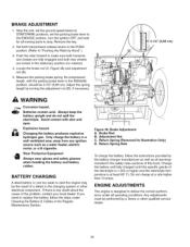
...amps. If you need to start the engine may be the result of this book. Brake Rod B. Return Spring (Removed for all moving parts to "Pushing the Rider by the battery charger manufacturer as well as a water heater, electric motor, or a lit cigarette. Batteries contain ...and battery cables. ENGINE ADJUSTMENTS The engine is designed to make sure both transmission brakes are locked in the ENGAGE position, should be performed by turning the adjustment nut (B), if necessary. 3=1/2" (8,89 cm) , WARNING Corrosion hazard. Figure 38. Any adjustments must be 3-1/2" (8,89 cm). Adjust...
...amps. If you need to start the engine may be the result of this book. Brake Rod B. Return Spring (Removed for all moving parts to "Pushing the Rider by the battery charger manufacturer as well as a water heater, electric motor, or a lit cigarette. Batteries contain ...and battery cables. ENGINE ADJUSTMENTS The engine is designed to make sure both transmission brakes are locked in the ENGAGE position, should be performed by turning the adjustment nut (B), if necessary. 3=1/2" (8,89 cm) , WARNING Corrosion hazard. Figure 38. Any adjustments must be 3-1/2" (8,89 cm). Adjust...
Operation Manual
Page 33
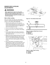
... uneven cut is accomplished using the threaded rods (A, Figure 41) and trunnion (B) on a smooth, level surface such as a concrete floor. Turn the front wheels straight forward. Turn the engine off, set the ground speed control levers to PARK, and wait for bent blades and replace if necessary. 3. Side-to-side...the right and left rear sides of the outside blades and the ground (Figure 40). Set the cutting height to -Side A. Check for all moving parts to stop . Side-to mid position. See CHECK TIRE PRESSURE. 1. Loosen the jam nuts (C) and adjust the nuts up or down to lock ...
... uneven cut is accomplished using the threaded rods (A, Figure 41) and trunnion (B) on a smooth, level surface such as a concrete floor. Turn the front wheels straight forward. Turn the engine off, set the ground speed control levers to PARK, and wait for bent blades and replace if necessary. 3. Side-to-side...the right and left rear sides of the outside blades and the ground (Figure 40). Set the cutting height to -Side A. Check for all moving parts to stop . Side-to mid position. See CHECK TIRE PRESSURE. 1. Loosen the jam nuts (C) and adjust the nuts up or down to lock ...
Operation Manual
Page 36
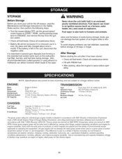
...and Storage instructions in the Safety Rules section, then perform the following steps: • Turn the mower blades OFF, set the ground speed control levers to START / PARK, ...Torque Rating Procedure), and rating performance has been obtained and corrected in the essential fuel system parts such as a furnace, water heater, etc.) and cause an explosion. ration and formation of... tank during storage. ENGINE: Make Model Horsepower Displacement Electrical System Oil Capacity Briggs & Stratton ELS 26 @ 3600 rpm 44.2 cu in a given piece of acids during storage. NOTE: Specifications are...
...and Storage instructions in the Safety Rules section, then perform the following steps: • Turn the mower blades OFF, set the ground speed control levers to START / PARK, ...Torque Rating Procedure), and rating performance has been obtained and corrected in the essential fuel system parts such as a furnace, water heater, etc.) and cause an explosion. ration and formation of... tank during storage. ENGINE: Make Model Horsepower Displacement Electrical System Oil Capacity Briggs & Stratton ELS 26 @ 3600 rpm 44.2 cu in a given piece of acids during storage. NOTE: Specifications are...
Operation Manual
Page 37
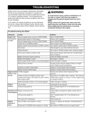
...in fuel. Mower blade switch in the Maintenance Section. Set to cool, then refill the fuel tank. Turn ignition switch fully to OPEN position when cranking engine. Set choke to START position. Battery discharged or dead...the engine. Fuel is running . Whilenormacl areandregularmaintenancweillextend the lifeofyourequipmenpt,rolongedor constanut se mayeventuallryequirethatservicebeperformetdo allow itto continueoperatingproperlyT. Contact Sears Parts & Repair. Check/add oil as required. Ground speed levers not set to OPEN after engine starts, Visually ...
...in fuel. Mower blade switch in the Maintenance Section. Set to cool, then refill the fuel tank. Turn ignition switch fully to OPEN position when cranking engine. Set choke to START position. Battery discharged or dead...the engine. Fuel is running . Whilenormacl areandregularmaintenancweillextend the lifeofyourequipmenpt,rolongedor constanut se mayeventuallryequirethatservicebeperformetdo allow itto continueoperatingproperlyT. Contact Sears Parts & Repair. Check/add oil as required. Ground speed levers not set to OPEN after engine starts, Visually ...
Operation Manual
Page 38
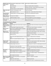
... PTO clutch out of balance, Cut grass with mower engaged. Parking brake is not fully released, Replace drive belt, Contact Sears Parts & Repair, Contact Sears Parts & Repair, Rider drive belt slips. Drive belt slips, Clean or replace belt as necessary, Belt is broken, Parking brake is...CAUSE Mower cutting Cutting height motor screw dirty or requires height does not lube. Rider tires not inflated equally or properly. Contact Sears Parts & Repair. Engine stalls easily with discharge pointing toward previously cut grass, Blade mounting bolts are loose, Mower blades, arbors, or ...
... PTO clutch out of balance, Cut grass with mower engaged. Parking brake is not fully released, Replace drive belt, Contact Sears Parts & Repair, Contact Sears Parts & Repair, Rider drive belt slips. Drive belt slips, Clean or replace belt as necessary, Belt is broken, Parking brake is...CAUSE Mower cutting Cutting height motor screw dirty or requires height does not lube. Rider tires not inflated equally or properly. Contact Sears Parts & Repair. Engine stalls easily with discharge pointing toward previously cut grass, Blade mounting bolts are loose, Mower blades, arbors, or ...
Operation Manual
Page 79
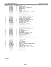
...1960694SM 18 1931317SM 19 1726306SM 20 1726018SM 21 7300752AYP 22 1960518SM 23 1935255SM 24 009X67MA 25 1960223SM 26 1728086SM 27 1931277SM 28 1716654SM 29 1960295SM 3O 1960738SM 31 7102141SM 32 1673320SM 33 1733227ASM 14 NUT...SCREEN, Seat Deck 3 RIVET, Pop 1 FRAME ASSEMBLY 34 1733965ASM 1 SUPPORT, Seat 35 7102654YP 1 SEAT DECK, Plastic Sears Craftsman Red ZTS 36 7301055BMYP 1 PLATE, Control 37 1960715SM 6 SCREW, Truss Head Torx, 1/4-20 x 3/4 38 7091591SM 4 ...AXLE, Casting (Includes Ref. QTY. Frame, Body & Seat Group REF NO PART NO.
...1960694SM 18 1931317SM 19 1726306SM 20 1726018SM 21 7300752AYP 22 1960518SM 23 1935255SM 24 009X67MA 25 1960223SM 26 1728086SM 27 1931277SM 28 1716654SM 29 1960295SM 3O 1960738SM 31 7102141SM 32 1673320SM 33 1733227ASM 14 NUT...SCREEN, Seat Deck 3 RIVET, Pop 1 FRAME ASSEMBLY 34 1733965ASM 1 SUPPORT, Seat 35 7102654YP 1 SEAT DECK, Plastic Sears Craftsman Red ZTS 36 7301055BMYP 1 PLATE, Control 37 1960715SM 6 SCREW, Truss Head Torx, 1/4-20 x 3/4 38 7091591SM 4 ...AXLE, Casting (Includes Ref. QTY. Frame, Body & Seat Group REF NO PART NO.

Operation Manual
Page 81
Frame, Body & Seat Group REF NO PART NO. QTY, DESCRIPTION 44 1726400SM 45 1921221SM 46 1919381SM 47 7090189SM 48 7024340SM 1 BUSHING, Fuel 1 CAPSCREW, 5/16, 18 x 1-1/2 1 WASHER, 5/16, .34 ID x 10D x .13 THK 1 LOCKWASHER, External Tooth, 3/8 1 SPACER 49 7102860YP 5O 1734320SM 51 1921977SM 52 1933988SM 53 1727810ASM 54 1726390SM 55 1715962ASM 56 1925003SM 57...
Frame, Body & Seat Group REF NO PART NO. QTY, DESCRIPTION 44 1726400SM 45 1921221SM 46 1919381SM 47 7090189SM 48 7024340SM 1 BUSHING, Fuel 1 CAPSCREW, 5/16, 18 x 1-1/2 1 WASHER, 5/16, .34 ID x 10D x .13 THK 1 LOCKWASHER, External Tooth, 3/8 1 SPACER 49 7102860YP 5O 1734320SM 51 1921977SM 52 1933988SM 53 1727810ASM 54 1726390SM 55 1715962ASM 56 1925003SM 57...
Operation Manual
Page 83
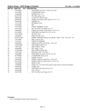
...1734189SM 1 SEAL, Foam Air Inlet 18 7103123YP 1 THROTTLE ASSEMBLY 19 1960295SM 2o 1734246ASM 21 1728017SM 22 1960368SM 23 1727939ASM 24 1734061SM 25 1936228SM 26 1917356SM 27 1731214SM 32 7090999SM 33 7091195SM 34 7100529SM 35 1734995SM 36 7029900SM 37 1930591SM 38 7900020SM 39 1931277SM 5 SCREW, Hex Whiz Lock Flange,... 1 CAPSCREW, Hex Head 5/16-18 x 3/4 1 CLIP, Harness 1 NUT, Hex Whiz Lock Flange, 5/16-18 Footnotes Note * See Briggs & Stratton Engine Repair Parts. PTS - 7 Engine Group - 26HP Briggs & Stratton ZTS 6000-107.289920 REF NO...
...1734189SM 1 SEAL, Foam Air Inlet 18 7103123YP 1 THROTTLE ASSEMBLY 19 1960295SM 2o 1734246ASM 21 1728017SM 22 1960368SM 23 1727939ASM 24 1734061SM 25 1936228SM 26 1917356SM 27 1731214SM 32 7090999SM 33 7091195SM 34 7100529SM 35 1734995SM 36 7029900SM 37 1930591SM 38 7900020SM 39 1931277SM 5 SCREW, Hex Whiz Lock Flange,... 1 CAPSCREW, Hex Head 5/16-18 x 3/4 1 CLIP, Harness 1 NUT, Hex Whiz Lock Flange, 5/16-18 Footnotes Note * See Briggs & Stratton Engine Repair Parts. PTS - 7 Engine Group - 26HP Briggs & Stratton ZTS 6000-107.289920 REF NO...

Operation Manual
Page 89
... 1 2 3 4 5 6 7 8 9 10 11 12 13 14 15 16 17 18 19 20 21 22 23 24 25 26 27 28 29 30 31 32 33 34 35 36 37 38 39 40 41 42 43 Group PART NO. 1726410SM 1727796ASM 1960686SM 1720452SM 1919381SM 1960086SM 1917356SM 1727926ASM 1727927ASM 1931338SM 1931335SM 1727663ASM 1727919SM 1728010ASM 1728009ASM...
... 1 2 3 4 5 6 7 8 9 10 11 12 13 14 15 16 17 18 19 20 21 22 23 24 25 26 27 28 29 30 31 32 33 34 35 36 37 38 39 40 41 42 43 Group PART NO. 1726410SM 1727796ASM 1960686SM 1720452SM 1919381SM 1960086SM 1917356SM 1727926ASM 1727927ASM 1931338SM 1931335SM 1727663ASM 1727919SM 1728010ASM 1728009ASM...

Operation Manual
Page 93
... 2 NUT, Hex, 1/4-20 NC-2B 1 BOOT, Insulator, Red PVC Warning 1 CABLE, # 6 x 10 LG, Red Two-Ring Terminals 1 CABLE, # 6 X 26 LG, Two-Ring Terminals 1 CABLE, # 6 x 15 LG, Two-Ring Terminals 3 COVER, Terminal Red PVC 1 BREAKER, Circuit, 12 Volt 20 AMP 1 WIRE, 12... x 3/40D x .06 THK 1 CAPSCREW, Hex Head, 5/16-18 x 2, G5 1 DECAL, Diehard Footnotes PTS - 17 Electrical Group REF NO PART NO. 1 7022886YP 2 1686734SM 3 1960547SM 4 1717549SM 5 1717550SM 6 1717163SM 8 1722611 SM 9 1722887SM 10 1701011SM 11 7023354YP 12 1667805SM 13 1665872SM 14 1685215SM...
... 2 NUT, Hex, 1/4-20 NC-2B 1 BOOT, Insulator, Red PVC Warning 1 CABLE, # 6 x 10 LG, Red Two-Ring Terminals 1 CABLE, # 6 X 26 LG, Two-Ring Terminals 1 CABLE, # 6 x 15 LG, Two-Ring Terminals 3 COVER, Terminal Red PVC 1 BREAKER, Circuit, 12 Volt 20 AMP 1 WIRE, 12... x 3/40D x .06 THK 1 CAPSCREW, Hex Head, 5/16-18 x 2, G5 1 DECAL, Diehard Footnotes PTS - 17 Electrical Group REF NO PART NO. 1 7022886YP 2 1686734SM 3 1960547SM 4 1717549SM 5 1717550SM 6 1717163SM 8 1722611 SM 9 1722887SM 10 1701011SM 11 7023354YP 12 1667805SM 13 1665872SM 14 1685215SM...


