
Operation Manual
Page 1
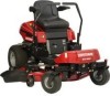
... Craftsman website: www.sears.com/craftsman 7103149 Revision F Rev. Operator's anual T ° ZTS Zero-Turn Rear Engine Riders with Electric Start Model No. 107.289920 (26HP Briggs & Stratton Engine with 52" Mower) CAUTION: Before using this Nota: Una traducci6n en espaSol de este Manual del Operador puede encontrarse en la pagina 39. Sat about this product, read the manual and follow all its Safety Rules and Operating Instructions...
... Craftsman website: www.sears.com/craftsman 7103149 Revision F Rev. Operator's anual T ° ZTS Zero-Turn Rear Engine Riders with Electric Start Model No. 107.289920 (26HP Briggs & Stratton Engine with 52" Mower) CAUTION: Before using this Nota: Una traducci6n en espaSol de este Manual del Operador puede encontrarse en la pagina 39. Sat about this product, read the manual and follow all its Safety Rules and Operating Instructions...
Operation Manual
Page 3
... 3 Safety Rules & Information 4 Identification Numbers 9 Assembly 10 Pre-Operation 14 Operation 15 Maintenance 22 Service & Adjustments 31 Storage 36 Specifications 36 Troubleshooting 37 Spanish Operator's Manual 39 Repair Parts PTS-1 Hardware and Torque Specifictions PTS-42 Repair Protection Agreement ........ Sears, Roebuck and Co., Hoffman Estates, IL 60179 3 CRAFTSMAN FULL WARRANTY When operated and maintained according to the instructions contained in the operator's manual. • Engine (fuel system) cleaning or repairs caused by punctures from outside...
... 3 Safety Rules & Information 4 Identification Numbers 9 Assembly 10 Pre-Operation 14 Operation 15 Maintenance 22 Service & Adjustments 31 Storage 36 Specifications 36 Troubleshooting 37 Spanish Operator's Manual 39 Repair Parts PTS-1 Hardware and Torque Specifictions PTS-42 Repair Protection Agreement ........ Sears, Roebuck and Co., Hoffman Estates, IL 60179 3 CRAFTSMAN FULL WARRANTY When operated and maintained according to the instructions contained in the operator's manual. • Engine (fuel system) cleaning or repairs caused by punctures from outside...

Operation Manual
Page 4
... unattended, lower the cutting means unless a positive mechanical lock is clear of alcohol or drugs. 15 Watch for proper start-up and thrown by the blade(s). 5. Always follow the engine manual instructions for traffic when operating near rotating parts or under the influence of other people before starting. 2. Clear the area of hearing protection when exposed to use of objects such as...
... unattended, lower the cutting means unless a positive mechanical lock is clear of alcohol or drugs. 15 Watch for proper start-up and thrown by the blade(s). 5. Always follow the engine manual instructions for traffic when operating near rotating parts or under the influence of other people before starting. 2. Clear the area of hearing protection when exposed to use of objects such as...
Operation Manual
Page 7
... pressure may ignite. If leaks occur, have dissipated. 13. Stop the engine and wait until it must be drained outdoors. 14. Use only approved gasoline containers. 3. Service & Maintenance 1. Keep nuts and bolts, especially blade attachment bolts, tight and keep equipment in handling gasoline and other fuels. Mower blades are in serious personal injury. Check brake operation frequently. Do not remove the fuel filter when the engine is spilled, do not attempt to start the engine...
... pressure may ignite. If leaks occur, have dissipated. 13. Stop the engine and wait until it must be drained outdoors. 14. Use only approved gasoline containers. 3. Service & Maintenance 1. Keep nuts and bolts, especially blade attachment bolts, tight and keep equipment in handling gasoline and other fuels. Mower blades are in serious personal injury. Check brake operation frequently. Do not remove the fuel filter when the engine is spilled, do not attempt to start the engine...

Operation Manual
Page 14
... document. Use fuel stabilizer to the oil fill tube. Pressure: 10=12 PSI Front Tire Pressure: 18=20 PSi Check Engine Oil Level Note: Engine is not covered under your fuel, and always store fuel in the operator's manual. Remove and check the engine oil level. Fuel Tank Capacity: 4.0 Gallons (15,14 L) Start the Engine and Drive the Unit Off the Crate Refer to the correct pressures for battery charging information. 14 Insert the dip stick into service after...
... document. Use fuel stabilizer to the oil fill tube. Pressure: 10=12 PSI Front Tire Pressure: 18=20 PSi Check Engine Oil Level Note: Engine is not covered under your fuel, and always store fuel in the operator's manual. Remove and check the engine oil level. Fuel Tank Capacity: 4.0 Gallons (15,14 L) Start the Engine and Drive the Unit Off the Crate Refer to the correct pressures for battery charging information. 14 Insert the dip stick into service after...
Operation Manual
Page 16
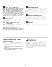
... a specific control functions, or have not yet thoroughly read all of ALL controls. 16 Ignition Switch The ignition switch starts and stops the engine; Fuel Tank To remove the fuel tank cap, turn it has three positions: OFF Stops the engine and shuts off . The cutting height gauge indicates the position of the switch. To decrease mower cutting height (lower the mower deck), press the bottom of the mower deck. Mower Cutting Height Switch To increase the mower cutting height (raise the mower deck), press...
... a specific control functions, or have not yet thoroughly read all of ALL controls. 16 Ignition Switch The ignition switch starts and stops the engine; Fuel Tank To remove the fuel tank cap, turn it has three positions: OFF Stops the engine and shuts off . The cutting height gauge indicates the position of the switch. To decrease mower cutting height (lower the mower deck), press the bottom of the mower deck. Mower Cutting Height Switch To increase the mower cutting height (raise the mower deck), press...
Operation Manual
Page 17
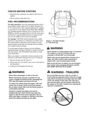
... rear wheels of this zero-turn rider on a trailer or truck using ethanol or methanol) can damage the fuel system of an engine while in storage. Install and hand tighten the fuel cap. Mow across the face of slopes, not up to a maximum of grass, leaves and excess grease. Before leaving the operator's position for any spills. Never fill the tank when the engine is...
... rear wheels of this zero-turn rider on a trailer or truck using ethanol or methanol) can damage the fuel system of an engine while in storage. Install and hand tighten the fuel cap. Mow across the face of slopes, not up to a maximum of grass, leaves and excess grease. Before leaving the operator's position for any spills. Never fill the tank when the engine is...

Operation Manual
Page 18
... speed control levers are locked in across the operator's lap). 7. For normal engine shut down ). 9. Engage the parking brake. 3. Warm the engine by running it for starting a cold engine. Locate the transmission release levers (C, Figure 8) at full throttle. 6. Pull the ground speed control levers in STOPPING THE RIDER AND ENGINE. Do not use another vehicle or object. Turn off the mower blades by pushing the mower blade switch down to release the transmissions (position B, Figure 8). 4. Move the throttle/choke control to the CHOKE position...
... speed control levers are locked in across the operator's lap). 7. For normal engine shut down ). 9. Engage the parking brake. 3. Warm the engine by running it for starting a cold engine. Locate the transmission release levers (C, Figure 8) at full throttle. 6. Pull the ground speed control levers in STOPPING THE RIDER AND ENGINE. Do not use another vehicle or object. Turn off the mower blades by pushing the mower blade switch down to release the transmissions (position B, Figure 8). 4. Move the throttle/choke control to the CHOKE position...
Operation Manual
Page 22
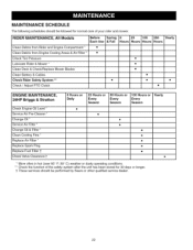
... and Engine Compartment * • Clean Debris from Engine Cooling Areas & Air Filter * • Check Tire Pressure Lubricate Rider & Mower * Clean Deck & Check/Replace Mower Blades Clean Battery & Cables Check Rider Safety System ** • Check / Adjust PTO Clutch • • • • • • • ENGINE MAINTENANCE, 26HP Briggs & Stratton Check Engine Oil Level * Service Air Pre-Cleaner * Change Oil * Service Air Filter * Change Oil & Filter * Clean Cooling Fins * Replace Air Filter * Replace Spark Plug Replace Fuel Filter 1 Check Valve Clearance...
... and Engine Compartment * • Clean Debris from Engine Cooling Areas & Air Filter * • Check Tire Pressure Lubricate Rider & Mower * Clean Deck & Check/Replace Mower Blades Clean Battery & Cables Check Rider Safety System ** • Check / Adjust PTO Clutch • • • • • • • ENGINE MAINTENANCE, 26HP Briggs & Stratton Check Engine Oil Level * Service Air Pre-Cleaner * Change Oil * Service Air Filter * Change Oil & Filter * Clean Cooling Fins * Replace Air Filter * Replace Spark Plug Replace Fuel Filter 1 Check Valve Clearance...

Operation Manual
Page 26
... the battery cables: first attach the positive cable (see A, Figure 27), then attach the negative cable (B). . Figure 27. These safety systems are not in their START/PARK positions, AND • Parking brake lever is equipped with petroleum jelly or non-conducting grease. Clean the battery and battery compartment with a wire brush until shiny. 5. Negative (-) Battery Cable CHECK RIDER SAFETY SYSTEM Service Interval: Every 100 hours, every spring/fall, and after the mower blade switch is...
... the battery cables: first attach the positive cable (see A, Figure 27), then attach the negative cable (B). . Figure 27. These safety systems are not in their START/PARK positions, AND • Parking brake lever is equipped with petroleum jelly or non-conducting grease. Clean the battery and battery compartment with a wire brush until shiny. 5. Negative (-) Battery Cable CHECK RIDER SAFETY SYSTEM Service Interval: Every 100 hours, every spring/fall, and after the mower blade switch is...
Operation Manual
Page 27
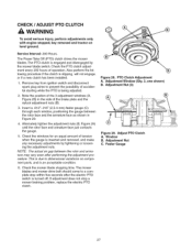
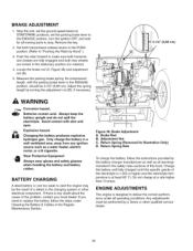
...a new clutch has been installed. 1. Window B. Adjustment Nut C. Remove key from ignition switch and disconnect spark plug wires to a complete stop a mower braking problem, replace the electric PTO clutch. Figure 28. Adjust PTO Clutch A. Insert a .012"-.015" (2,5-4 mm) feeler gauge (C) through each window, positioning the gauge between the rotor and armature may vary even after the electric PTO switch is being adjusted. 2. Check the mower blade stopping time. Adjustment Nut (3) Figure 29. The Power Take Off (PTO) clutch drives the mower blades. If adjustment does...
...a new clutch has been installed. 1. Window B. Adjustment Nut C. Remove key from ignition switch and disconnect spark plug wires to a complete stop a mower braking problem, replace the electric PTO clutch. Figure 28. Adjust PTO Clutch A. Insert a .012"-.015" (2,5-4 mm) feeler gauge (C) through each window, positioning the gauge between the rotor and armature may vary even after the electric PTO switch is being adjusted. 2. Check the mower blade stopping time. Adjustment Nut (3) Figure 29. The Power Take Off (PTO) clutch drives the mower blades. If adjustment does...

Operation Manual
Page 28
... oil drain tube (A). 2. Thread the cap back into the engine. Start and run the engine to warm. 1. Clean the area around the dip stick (C, Figure 31) and oil drain (A). 2. Oil Change A. Test run the engine at SLOW speed for 30 seconds. Engine Maintenance Items CHECK ENGINE OIL LEVEL Service Interval: Before each use of the new filter. 5. Fill the crankcase with oil. NOTE: Change engine oil while the engine is warm. Insert the dip stick back into the tube (D). 5. Remove the oil drain plug...
... oil drain tube (A). 2. Thread the cap back into the engine. Start and run the engine to warm. 1. Clean the area around the dip stick (C, Figure 31) and oil drain (A). 2. Oil Change A. Test run the engine at SLOW speed for 30 seconds. Engine Maintenance Items CHECK ENGINE OIL LEVEL Service Interval: Before each use of the new filter. 5. Fill the crankcase with oil. NOTE: Change engine oil while the engine is warm. Insert the dip stick back into the tube (D). 5. Remove the oil drain plug...
Operation Manual
Page 31
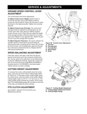
... CLUTCH ADJUSTMENT See CHECK / ADJUST PTO CLUTCH in the maximum forward position, the top speed of the mower deck. Cutting Height Gauge 31 GROUND SPEED CONTROL LEVER ADJUSTMENT The control levers have three adjustments: To Adjust Control Lever Height: Pull the levers in across the operator's lap to the desired position. Loosen the mount bolts (D, Figure 36) and raise or lower the levers to their DRIVE positions. Tighten the mounting bolts.(D). To Adjust Control Lever End Gap: The control lever end gap should be balanced by removing the...
... CLUTCH ADJUSTMENT See CHECK / ADJUST PTO CLUTCH in the maximum forward position, the top speed of the mower deck. Cutting Height Gauge 31 GROUND SPEED CONTROL LEVER ADJUSTMENT The control levers have three adjustments: To Adjust Control Lever Height: Pull the levers in across the operator's lap to the desired position. Loosen the mount bolts (D, Figure 36) and raise or lower the levers to their DRIVE positions. Tighten the mounting bolts.(D). To Adjust Control Lever End Gap: The control lever end gap should be balanced by removing the...
Operation Manual
Page 32
... of the problem, contact your local dealer. Brake Adjustment A. Any adjustments must be 3-1/2" (8,89 cm). BRAKE ADJUSTMENT 1. Stop the unit, set the ground speed levers to START/PARK positions, set the parking brake lever to the ENGAGE position, turn the ignition OFF, and wait for Illustration Only) D. Adjust the spring length by a Sears or other electrical component. Explosion hazard. Only charge the battery in the charging system or other qualified service dealer. 32...
... of the problem, contact your local dealer. Brake Adjustment A. Any adjustments must be 3-1/2" (8,89 cm). BRAKE ADJUSTMENT 1. Stop the unit, set the ground speed levers to START/PARK positions, set the parking brake lever to the ENGAGE position, turn the ignition OFF, and wait for Illustration Only) D. Adjust the spring length by a Sears or other electrical component. Explosion hazard. Only charge the battery in the charging system or other qualified service dealer. 32...
Operation Manual
Page 33
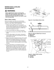
... Figure 40. Mower Deck B. Arrange the mower blades so that they are pointing from the spark plug. Figure 39. Orient Blades Side-to Front To Back Leveling. 6. Threaded Rod B. Side to Step 6. See CHECK TIRE PRESSURE. 1. Jam Nuts Leveling 33 Check the tire pressures. MOWER DECK LEVELING ADJUSTMENTS WARNING Before adjusting the mower, turn the mower blades OFF, turn the ignition switch OFF, remove the key, and allow all moving parts to stop . 2. Disconnect the spark plug wire and fasten it...
... Figure 40. Mower Deck B. Arrange the mower blades so that they are pointing from the spark plug. Figure 39. Orient Blades Side-to Front To Back Leveling. 6. Threaded Rod B. Side to Step 6. See CHECK TIRE PRESSURE. 1. Jam Nuts Leveling 33 Check the tire pressures. MOWER DECK LEVELING ADJUSTMENTS WARNING Before adjusting the mower, turn the mower blades OFF, turn the ignition switch OFF, remove the key, and allow all moving parts to stop . 2. Disconnect the spark plug wire and fasten it...
Operation Manual
Page 36
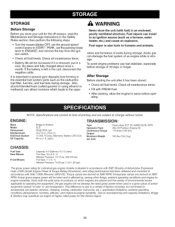
... to operating the equipment, the gas engine will be increased if it has been stored: • Check all fluid levels. Fuel vapor is important to prevent gum deposits from the ignition switch. • Check all fluid levels. Also, alcohol blended fuels (called gasohol or using ethanol or methanol) can travel to an ignition source (such as the carburetor, fuel filter, fuel line, and fuel tank during storage. Check all maintenance items. • Battery...
... to operating the equipment, the gas engine will be increased if it has been stored: • Check all fluid levels. Fuel vapor is important to prevent gum deposits from the ignition switch. • Check all fluid levels. Also, alcohol blended fuels (called gasohol or using ethanol or methanol) can travel to an ignition source (such as the carburetor, fuel filter, fuel line, and fuel tank during storage. Check all maintenance items. • Battery...
Operation Manual
Page 37
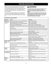
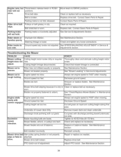
... oil. Check/add oil as required. Using wrong weight oil. Choke set to START/PARK. iTroubleshooting the Rider PROBLEM CAUSE REMEDY Engine will not turnover i or start. Ground speed levers not set to prevent accidental starting of fuel. Set to START/PARK. Set to START/PARK. Turn ignition switch fully to OPEN position when cranking engine. Battery discharged or dead. Clean the battery terminals. Wiring loose or broken. Contact Sears Parts & Repair Replace. Low oil level. Too much oil in CLOSED position. See "Change Engine Oil" in ON position. Always remove...
... oil. Check/add oil as required. Using wrong weight oil. Choke set to START/PARK. iTroubleshooting the Rider PROBLEM CAUSE REMEDY Engine will not turnover i or start. Ground speed levers not set to prevent accidental starting of fuel. Set to START/PARK. Set to START/PARK. Turn ignition switch fully to OPEN position when cranking engine. Battery discharged or dead. Clean the battery terminals. Wiring loose or broken. Contact Sears Parts & Repair Replace. Low oil level. Too much oil in CLOSED position. See "Change Engine Oil" in ON position. Always remove...
Operation Manual
Page 38
... Ground Speed, Cut tall grass at maximum cutting height during first pass, Remove mower deck and clean underside, Excessive mower vibration, Discharge chute jamming with cut is Engine speed too slow, Always set too low. Engineruns,but Transmissiorneleaseleversin PUSH MoveleverstoDRIVEpositions. See Service & Adjustments Section, Rider steers or handles poorly. Steering linkage is oily or Clean or replace belt as necessary, Replace or balance blades, See Maintenance Section, Belt installed incorrectly, Reinstall correctly, Mower drive belt Idler pulley spring broken or...
... Ground Speed, Cut tall grass at maximum cutting height during first pass, Remove mower deck and clean underside, Excessive mower vibration, Discharge chute jamming with cut is Engine speed too slow, Always set too low. Engineruns,but Transmissiorneleaseleversin PUSH MoveleverstoDRIVEpositions. See Service & Adjustments Section, Rider steers or handles poorly. Steering linkage is oily or Clean or replace belt as necessary, Replace or balance blades, See Maintenance Section, Belt installed incorrectly, Reinstall correctly, Mower drive belt Idler pulley spring broken or...

Operation Manual
Page 105
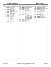
... interchangeable) Seat-O Ring (Oil Pump Cover) Cover-Oil Pump Nipple-Oil Filter Screen-Oil Pump Pump-Oil Filter-Oil 277103 Operator's Manual 44Q777-0037-G1 (Replacement Engine) 273521 Repair Manual MCS000001 Assemblies include all parts shown in frames. 29 12/22/2008 DESCRIPTION 796223 690957 794389 792651 691108 690442 690283 691029 691036 691032 691037 690552 690553 690311 LeverGovernor Control Retainer-Breather Collector-Oil Washer (Governor Control Lever) Screw (Dipstick Tube) Washer (Governor Crank) Plug (Oil Pressure Switch Hole) Nut (Governor Control Lever) Dipstick Seal-Dipstick...
... interchangeable) Seat-O Ring (Oil Pump Cover) Cover-Oil Pump Nipple-Oil Filter Screen-Oil Pump Pump-Oil Filter-Oil 277103 Operator's Manual 44Q777-0037-G1 (Replacement Engine) 273521 Repair Manual MCS000001 Assemblies include all parts shown in frames. 29 12/22/2008 DESCRIPTION 796223 690957 794389 792651 691108 690442 690283 691029 691036 691032 691037 690552 690553 690311 LeverGovernor Control Retainer-Breather Collector-Oil Washer (Governor Control Lever) Screw (Dipstick Tube) Washer (Governor Crank) Plug (Oil Pressure Switch Hole) Nut (Governor Control Lever) Dipstick Seal-Dipstick...
Operation Manual
Page 109
... Gasket-Cylinder Head 13 793988 Screw (Cylinder Head) 33 793557 Valve-Exhaust 34 793556 Valve-Intake 35 694865 Spring-Valve (Intake) 36 694865 Spring-Valve (Exhaust) 40 690964 Retainer-Valve 42 499586 Keeper-Valve 45 690977 Tappet-Valve REF. NO. PART NO. DESCRIPTION 192 690083 Adjuster-Rocker Arm 337 491055s Plug-Spark 617 697891 Seal-O Ring (Intake Manifold) (Red) 635 66538s Boot-Spark Plug 798 697890 Screw (Rocker Arm...
... Gasket-Cylinder Head 13 793988 Screw (Cylinder Head) 33 793557 Valve-Exhaust 34 793556 Valve-Intake 35 694865 Spring-Valve (Intake) 36 694865 Spring-Valve (Exhaust) 40 690964 Retainer-Valve 42 499586 Keeper-Valve 45 690977 Tappet-Valve REF. NO. PART NO. DESCRIPTION 192 690083 Adjuster-Rocker Arm 337 491055s Plug-Spark 617 697891 Seal-O Ring (Intake Manifold) (Red) 635 66538s Boot-Spark Plug 798 697890 Screw (Rocker Arm...


