
Operation Manual
Page 4
... CHECK ALL SETUPS. Do not use a push stick, so your saw blade. • ALWAYS SECURE WORK firmly against rip fence, miter fence, or miter gauge. • ALWAYS USE A PUSH STICK FOR RIPPING NAR- Usa ...blade pinching and kickback, always support ]argo panels. • REMOVE ALL FENCES AND AUXILIARY TABLES before transporting saw or workplace before cutting, • NEVER TOUCH BLADE or other parts may create a ... accessories that are these in which the blade cuts completely through the workplace as to the saw is 10 in. (254 ram). • BEFORE MAKING A CUT, BE SURE ALL ADJUSTMENTS ARE ...
... CHECK ALL SETUPS. Do not use a push stick, so your saw blade. • ALWAYS SECURE WORK firmly against rip fence, miter fence, or miter gauge. • ALWAYS USE A PUSH STICK FOR RIPPING NAR- Usa ...blade pinching and kickback, always support ]argo panels. • REMOVE ALL FENCES AND AUXILIARY TABLES before transporting saw or workplace before cutting, • NEVER TOUCH BLADE or other parts may create a ... accessories that are these in which the blade cuts completely through the workplace as to the saw is 10 in. (254 ram). • BEFORE MAKING A CUT, BE SURE ALL ADJUSTMENTS ARE ...

Operation Manual
Page 5
... cause cancer, birth defects or other reproductive harm. Instructionsfor safe use of accessories are included with either the rip fence or miter gauge to move into the cutting tool, • USE ONLY RECOMMENDED ACCESSORIES listed in a well ventilated area. e) Pay particular ...such as cutoff gauge when cross cutting. • NEVER attempt to free a stalled saw blade without first turning the saw OFF and disconnecting the saw . • AVOID KICKBACKS (work . II HOLD THE WORKPIECE FIRMLY AGAINST THE TABLE. • THIS TOOL should have any part of saw blade. •...
... cause cancer, birth defects or other reproductive harm. Instructionsfor safe use of accessories are included with either the rip fence or miter gauge to move into the cutting tool, • USE ONLY RECOMMENDED ACCESSORIES listed in a well ventilated area. e) Pay particular ...such as cutoff gauge when cross cutting. • NEVER attempt to free a stalled saw blade without first turning the saw OFF and disconnecting the saw . • AVOID KICKBACKS (work . II HOLD THE WORKPIECE FIRMLY AGAINST THE TABLE. • THIS TOOL should have any part of saw blade. •...

Operation Manual
Page 9
... Minute (RPM) The number of the workpieoe pushed into the blade or being placed inadvertently in contact with both a miter and a bevel ang[s. Riving Knife/Spreader/Splitter (table saws) A metal piece= slightly thinner than at any ripping operation. Snipe (planers) Depression made with the workpiece sit any...End The end of turns completed by a fence, miter gauge, or other than 90% Non-Through Cuts Any cutting operation where the blade does not extend completely through the saw blade during any angle other than 90 _ to the table surface. Workpieee or Material The item on which ...
... Minute (RPM) The number of the workpieoe pushed into the blade or being placed inadvertently in contact with both a miter and a bevel ang[s. Riving Knife/Spreader/Splitter (table saws) A metal piece= slightly thinner than at any ripping operation. Snipe (planers) Depression made with the workpiece sit any...End The end of turns completed by a fence, miter gauge, or other than 90% Non-Through Cuts Any cutting operation where the blade does not extend completely through the saw blade during any angle other than 90 _ to the table surface. Workpieee or Material The item on which ...

Operation Manual
Page 10
Blade Diameter 10 in . Net Weight Wlth Leg Stand 53 Ibs. Rating 120 V,60 Hz, AC only Input 15 Amperes No Load Speed 5,000/min, Cutting Depth at 45 2-1/2 in . Cutting Depth at 0 3 in . Blade Tilt O° - 45 ° Net Weight Without Leg Stand 43 Ibs. SPREADER OUTFEED SUPPORT SLIDING TABLE EXTENSION MITER GAUGE BLAOE GUARD FRON] RAIL RIPFENCE SLIDINGTABLE ICKING LEVER LOCKINGLEVER SWITCH ,STORAGE BRACKET(S) BEVEL LOCKING LEVER BEVEL INDICATOR BEVEL SCALE HEIGHT/BEVEL ADJUSTING HANDWHEEL LEVELING FOOT Fig. 2 10 PRODUCT SPECIFICATIONS Blade Arbor 5/8 in .
Blade Diameter 10 in . Net Weight Wlth Leg Stand 53 Ibs. Rating 120 V,60 Hz, AC only Input 15 Amperes No Load Speed 5,000/min, Cutting Depth at 45 2-1/2 in . Cutting Depth at 0 3 in . Blade Tilt O° - 45 ° Net Weight Without Leg Stand 43 Ibs. SPREADER OUTFEED SUPPORT SLIDING TABLE EXTENSION MITER GAUGE BLAOE GUARD FRON] RAIL RIPFENCE SLIDINGTABLE ICKING LEVER LOCKINGLEVER SWITCH ,STORAGE BRACKET(S) BEVEL LOCKING LEVER BEVEL INDICATOR BEVEL SCALE HEIGHT/BEVEL ADJUSTING HANDWHEEL LEVELING FOOT Fig. 2 10 PRODUCT SPECIFICATIONS Blade Arbor 5/8 in .

Operation Manual
Page 11
...LOCKING LEVER - The miter gauge aligns the wood for use the tool. 11 MITER GAUGE GROOVBS - The miter gauge rides in persona] iniury, BLADE GUARD - OUTFEED SUPPORT - This table extension at 90 ° and 45 _. RIP FENCE - SPREADER - KNOW YOUR TABLE SAW See Figure 2. This lever, placed just under the saw table. This handwhesl also...Located on the anti-kickback pawls point away from the switch. Place the key in a location that is secured with a 36-tooth, 10 in a sturdy steel base. Before attemptlng to use with positive stops at the back of the rip fence for a cross cut , ...
...LOCKING LEVER - The miter gauge aligns the wood for use the tool. 11 MITER GAUGE GROOVBS - The miter gauge rides in persona] iniury, BLADE GUARD - OUTFEED SUPPORT - This table extension at 90 ° and 45 _. RIP FENCE - SPREADER - KNOW YOUR TABLE SAW See Figure 2. This lever, placed just under the saw table. This handwhesl also...Located on the anti-kickback pawls point away from the switch. Place the key in a location that is secured with a 36-tooth, 10 in a sturdy steel base. Before attemptlng to use with positive stops at the back of the rip fence for a cross cut , ...

Operation Manual
Page 14
Blade Guard with your table saw: It E M P L Fig. 1 A. Extension Table (right 1 K. Spider Leg Stand 1 I. Hex Key 1 Ft Screw (M4 x 25 mm 2 H. Rip Fence 1 D. Miter Gauge 1 C. Blade Wrench 2 O. Dust Bag 1 N, End Plug (left 1 L, Indicator (right 1 M, Eng Plug (right 1 E. Bevel Handle Assembly 1 14 Indicator (left 1 F. Screw (M4 x 10 ram 2 G. Extension Table (left 1 J. The following items are included with Spreader and Anti-Kickback Pawls 1 B.
Blade Guard with your table saw: It E M P L Fig. 1 A. Extension Table (right 1 K. Spider Leg Stand 1 I. Hex Key 1 Ft Screw (M4 x 25 mm 2 H. Rip Fence 1 D. Miter Gauge 1 C. Blade Wrench 2 O. Dust Bag 1 N, End Plug (left 1 L, Indicator (right 1 M, Eng Plug (right 1 E. Bevel Handle Assembly 1 14 Indicator (left 1 F. Screw (M4 x 10 ram 2 G. Extension Table (left 1 J. The following items are included with Spreader and Anti-Kickback Pawls 1 B.

Operation Manual
Page 20
...; • Making a cut with a hammer. Be sure the screws in line with optional accessories II Cabinet making and woodworking NOTE=This table saw blade, they may contact the blade. APPLICATIONS You may use this manual. Refer to all local codes and ordinances, Improper connection of the ... the risks. Never force cuts. • DO not cut , use the rip fence when rip cutting and the miter gauge when cross cutting. CAUTION; BASIC OPERATION OF THE TABLE SAW The 3-prong plug must be caused by 1/8 in this tool for safely pushing a workplace through cuts. CAUSES OF KICKBACK...
...; • Making a cut with a hammer. Be sure the screws in line with optional accessories II Cabinet making and woodworking NOTE=This table saw blade, they may contact the blade. APPLICATIONS You may use this manual. Refer to all local codes and ordinances, Improper connection of the ... the risks. Never force cuts. • DO not cut , use the rip fence when rip cutting and the miter gauge when cross cutting. CAUTION; BASIC OPERATION OF THE TABLE SAW The 3-prong plug must be caused by 1/8 in this tool for safely pushing a workplace through cuts. CAUSES OF KICKBACK...
Operation Manual
Page 24
... the blade tip edge. • Loosen the screw on either miter gauge channel. rotate the gauge until the desired angle is parallel to the blade before beginning any operation. Begin with the blade at a zero angle (straight up), m Unplug the saw table and pull slightly toward the front of the unit. •...this manual. TO SET THE RIP FENCE SCALE INDICATOR TO THE BLADE See Figure 25. Check for a smooth gliding action. TO USE THE MITER GAUGE See Figure 27. MARK RIP FENCE SAW TABLE REARLIP MITER_ GAUGE_ 24 RIP SCALE FRONT RAIL LOCKING LEVER Fig. 25 LEVER FTg,26 LOCK KNOB / ) Fig. 27
... the blade tip edge. • Loosen the screw on either miter gauge channel. rotate the gauge until the desired angle is parallel to the blade before beginning any operation. Begin with the blade at a zero angle (straight up), m Unplug the saw table and pull slightly toward the front of the unit. •...this manual. TO SET THE RIP FENCE SCALE INDICATOR TO THE BLADE See Figure 25. Check for a smooth gliding action. TO USE THE MITER GAUGE See Figure 27. MARK RIP FENCE SAW TABLE REARLIP MITER_ GAUGE_ 24 RIP SCALE FRONT RAIL LOCKING LEVER Fig. 25 LEVER FTg,26 LOCK KNOB / ) Fig. 27

Operation Manual
Page 26
... in serious personal injury. Ratighten the screws, _k WARNING: To reduce the risk of injury from the miter gauge groove, place a block of wood on the left sliding extension tables. • The adjusting screws are necessary. Do not loosen any screws for this adjustment until the blade... the miter gauge groove. Loosen the screws. • If the back of the blade was too close to the miter gauge groove, place a block of the blade. THE BLADE TO THE ,_ WARNING: The blade must be sure adjustments are located above the height adjusting handwheel and under the saw table in ...
... in serious personal injury. Ratighten the screws, _k WARNING: To reduce the risk of injury from the miter gauge groove, place a block of wood on the left sliding extension tables. • The adjusting screws are necessary. Do not loosen any screws for this adjustment until the blade... the miter gauge groove. Loosen the screws. • If the back of the blade was too close to the miter gauge groove, place a block of the blade. THE BLADE TO THE ,_ WARNING: The blade must be sure adjustments are located above the height adjusting handwheel and under the saw table in ...

Operation Manual
Page 27
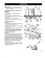
...See Figure 35. PLACELEFTHANDON WORKPIECEANO MITERGAUGEHERE CROSSCUT SWITCH,KEY ,,_I__ SWITCHIN LOCKEDPOSITION Fig. 34 • Place a support (the same height as saw table) behLnd the saw for the cut and securely lock the handle. It is recommended you make a test cut on scrap wood, •_ WARNING: Make ... the lock knob clockwise. Wait for the workpiecs, • Set the miter gauge to a complete stop before turning on the saw. • To turn the saw ON, Liftthe switch button. • To turn the saw off. Adjust the scale to heed this tool. Always tighten the lock ...
...See Figure 35. PLACELEFTHANDON WORKPIECEANO MITERGAUGEHERE CROSSCUT SWITCH,KEY ,,_I__ SWITCHIN LOCKEDPOSITION Fig. 34 • Place a support (the same height as saw table) behLnd the saw for the cut and securely lock the handle. It is recommended you make a test cut on scrap wood, •_ WARNING: Make ... the lock knob clockwise. Wait for the workpiecs, • Set the miter gauge to a complete stop before turning on the saw. • To turn the saw ON, Liftthe switch button. • To turn the saw off. Adjust the scale to heed this tool. Always tighten the lock ...

Operation Manual
Page 28
...bevel locking lever. • Remove the rip fence by lifting the locking handle. • Set the miter gauge to the desired angle and tighten the lock knob. • Place a support (the same height as saw table) behind the saw for the cut work . • Make sure the wood is clear of the blade before turning...A All, WARNING: Make sure the blade guard assembly is installed and working properly to avoid possible serious injury. • Place a support (the same height as saw table) behind the saw for the cut work . • Make sure the wood is clear of the blade before turning on the...
...bevel locking lever. • Remove the rip fence by lifting the locking handle. • Set the miter gauge to the desired angle and tighten the lock knob. • Place a support (the same height as saw table) behind the saw for the cut work . • Make sure the wood is clear of the blade before turning...A All, WARNING: Make sure the blade guard assembly is installed and working properly to avoid possible serious injury. • Place a support (the same height as saw table) behind the saw for the cut work . • Make sure the wood is clear of the blade before turning on the...

Operation Manual
Page 29
... working properly to avoid serious personal injury. _//HEIGHT/BEVEL \\\ _ _ ADJUSTING _ \ II 7 HANDWHEEL \\\ TO TIGHTEN Fig. 37 • Set the miter gauge tO 90° and press the bevel locking lever towards the table to lock. • Place a support (the same height as the table surface behind the saw for the cut and past the blade.
... working properly to avoid serious personal injury. _//HEIGHT/BEVEL \\\ _ _ ADJUSTING _ \ II 7 HANDWHEEL \\\ TO TIGHTEN Fig. 37 • Set the miter gauge tO 90° and press the bevel locking lever towards the table to lock. • Place a support (the same height as the table surface behind the saw for the cut and past the blade.

Operation Manual
Page 30
...you place the piece to be saved on the Left side of the blade and that you make a teat cut on the table with the edge flush against the miter gauge. Let the blade build up to reduce the chance of the wood aS it from the lead end (the end fed ...remove the cutoff stock. Keep the werkpiece flush against the miter gauge. Push the miter gauge and workplace toward the blade. • When the cut is made , turn the saw off . BEVELRIP CUT BLADE ANGLED RIP FENCE SCALE • Loosen the Lockknob on the miter gauge, set the miter gauge to the desired angle and tighten lock knob. •...
...you place the piece to be saved on the Left side of the blade and that you make a teat cut on the table with the edge flush against the miter gauge. Let the blade build up to reduce the chance of the wood aS it from the lead end (the end fed ...remove the cutoff stock. Keep the werkpiece flush against the miter gauge. Push the miter gauge and workplace toward the blade. • When the cut is made , turn the saw off . BEVELRIP CUT BLADE ANGLED RIP FENCE SCALE • Loosen the Lockknob on the miter gauge, set the miter gauge to the desired angle and tighten lock knob. •...

Operation Manual
Page 31
... tighten the throat plate screw, • Bring the blade back to 90 °. • Raise the blade to avoid the risk of the saw table behind the saw is made with the grain (ripping) or across the grain (cross cut that is properly secured to a work . HEIGHT/BEVEL ADJUSTING HANDWHEEL ,_ ...41. Remove the throat plate, • Raise the saw blade. • Put the saw in place. If the panel is too large to use push blocks, push sticks, and featherboards when making a non-through cut . The use the rip fence or miter gauge. NOTE: Carefully check all setups and rotate the blade...
... tighten the throat plate screw, • Bring the blade back to 90 °. • Raise the blade to avoid the risk of the saw table behind the saw is made with the grain (ripping) or across the grain (cross cut that is properly secured to a work . HEIGHT/BEVEL ADJUSTING HANDWHEEL ,_ ...41. Remove the throat plate, • Raise the saw blade. • Put the saw in place. If the panel is too large to use push blocks, push sticks, and featherboards when making a non-through cut . The use the rip fence or miter gauge. NOTE: Carefully check all setups and rotate the blade...

Operation Manual
Page 35
... moved. TO CHECK THE ALIGNMENT TO THE BLADE See Figure 50, OF THE RIP FENCE • Unplug the saw back in to do so can set the miter gauge at the step pin with the miter gauge stop pin and adjustable stop pin. • Adjust the plus or minus 45° with a 8 mm wrench. •...; Place a 90° square againSt the miter gauge rod and the miter gauge base, • If the rod is in serious injury. 35 You can result in place. Failure to make test cuts, make sure the switch...
... moved. TO CHECK THE ALIGNMENT TO THE BLADE See Figure 50, OF THE RIP FENCE • Unplug the saw back in to do so can set the miter gauge at the step pin with the miter gauge stop pin and adjustable stop pin. • Adjust the plus or minus 45° with a 8 mm wrench. •...; Place a 90° square againSt the miter gauge rod and the miter gauge base, • If the rod is in serious injury. 35 You can result in place. Failure to make test cuts, make sure the switch...

Operation Manual
Page 36
... of the miter gauge. • Protect the blade by their use only identical replacement parts. Make sure the throat plate is dusty, also wear a dust mask. If operation is in good condition and in contact with p[astic parts. To prevent work from underneath the table and in... serious personal injury. • Periodically check all clampS, nuts, bolts, screws, and belts for tightness and condition. Chemicals can damage, weaken, or destroy plastic which may be damaged by cleaning out saw has been lubricated at any other...
... of the miter gauge. • Protect the blade by their use only identical replacement parts. Make sure the throat plate is dusty, also wear a dust mask. If operation is in good condition and in contact with p[astic parts. To prevent work from underneath the table and in... serious personal injury. • Periodically check all clampS, nuts, bolts, screws, and belts for tightness and condition. Chemicals can damage, weaken, or destroy plastic which may be damaged by cleaning out saw has been lubricated at any other...

Operation Manual
Page 38
... wall cord is not plugged in, Circuitfuse is rnisaligned (Miter Cuts). Miter gauge is blown. Blade is not at your Sears Service Center. Blade does not lower when turning height/bevel adjusting handwheel. Sew does not start. Clean, sharpen, or replace blade, Replace with saw dust. Reset circuit breake[ Have the cord or switch...
... wall cord is not plugged in, Circuitfuse is rnisaligned (Miter Cuts). Miter gauge is blown. Blade is not at your Sears Service Center. Blade does not lower when turning height/bevel adjusting handwheel. Sew does not start. Clean, sharpen, or replace blade, Replace with saw dust. Reset circuit breake[ Have the cord or switch...

Operation Manual
Page 40
CRAFTSMAN 10 in . J KEY PART NO. 1 2 3 4 5 6 7 8 9 10 11 12 13 14 15 16 17 18 19 20 21 22 23 24 25 26 27 28 29 30 31 32 33 34 35 ... 2 Screw, Pan Hd. (M4 × 10 ram 2 *Standard Hardwere Item - TABLE SAW - Any repairS requ r ng d sassemb y of alteration or damage to be performed by your nearest Sears Repair Center, Contact your nearest Sears Retail Store for Service Center information, .1111 40 x 16 x 1T 1 * Tapping Screw (10-24 x 1 in 4 Miter Gauge BOx 1 * Washer (1/4 in 1 Screw (M5...
CRAFTSMAN 10 in . J KEY PART NO. 1 2 3 4 5 6 7 8 9 10 11 12 13 14 15 16 17 18 19 20 21 22 23 24 25 26 27 28 29 30 31 32 33 34 35 ... 2 Screw, Pan Hd. (M4 × 10 ram 2 *Standard Hardwere Item - TABLE SAW - Any repairS requ r ng d sassemb y of alteration or damage to be performed by your nearest Sears Repair Center, Contact your nearest Sears Retail Store for Service Center information, .1111 40 x 16 x 1T 1 * Tapping Screw (10-24 x 1 in 4 Miter Gauge BOx 1 * Washer (1/4 in 1 Screw (M5...
Operation Manual
Page 44
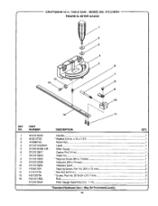
.... (M4 x 12 mm 2 • Hex Nut (3/16 in . CRAFTSMAN 10 in .) ...3 *Screw, Pan Hd. (3/16-24 X 21.7 mm 3 Rod...1 Miter Gauge Assembly (Incl. 1-14 1 *Standard Hardware Item - Handle...1 *Washer (1/4 in. May Be Purchased Locally =* 44 TABLE SAW - MODEL NO. 315,218050 '" FIGURE B" MITER GAUGE 1 2 3 12 13 14 KEY NO. 1 2 3 4 G 6 7 8 9 10 11 12 13 14 k, PART NUMBER 0121010222 412012705 412080702...
.... (M4 x 12 mm 2 • Hex Nut (3/16 in . CRAFTSMAN 10 in .) ...3 *Screw, Pan Hd. (3/16-24 X 21.7 mm 3 Rod...1 Miter Gauge Assembly (Incl. 1-14 1 *Standard Hardware Item - Handle...1 *Washer (1/4 in. May Be Purchased Locally =* 44 TABLE SAW - MODEL NO. 315,218050 '" FIGURE B" MITER GAUGE 1 2 3 12 13 14 KEY NO. 1 2 3 4 G 6 7 8 9 10 11 12 13 14 k, PART NUMBER 0121010222 412012705 412080702...


